Downloaded 7,938 times
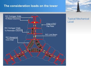
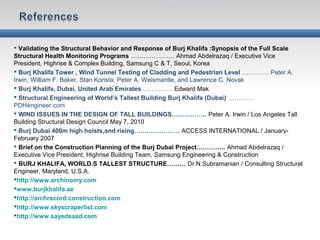
![The consideration loads on the tower:
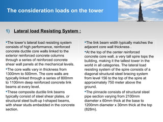
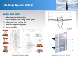
R/C Hammer Head Wall
[1300 mm]
R/C Corridor Shear Wall
[650 mm]
R/C Perimeter Column
[3500x600]
R/C Hexagonal Core
Wall [600mm]
R/C Nose Columns
[1500mm]
Edge of R/C
Flat Plate
R/C Link Beam
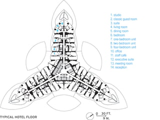
Typical Hotel Level](https://image.slidesharecdn.com/burjkhalifa-150516084413-lva1-app6892/85/Burj-khalifa-29-320.jpg)


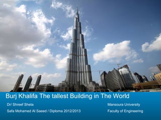
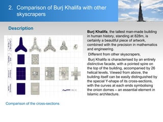
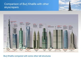
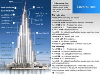
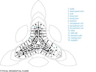
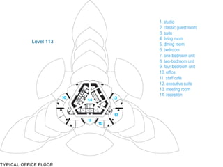
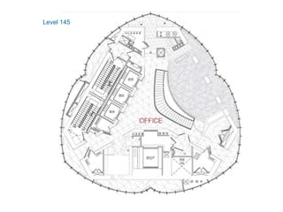
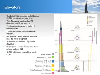
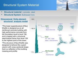
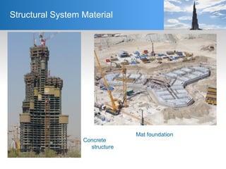
The document details the construction and design aspects of the Burj Khalifa, the world's tallest building at 828 meters, built between 2004 and 2010 at a cost of $4.1 billion. It discusses its architectural features, structural systems, and advanced safety measures, highlighting its unique Y-shaped design and the technologies implemented to withstand wind loads and earthquakes. Additionally, it covers the building's functional spaces, elevator systems, and material specifications used in its construction.


