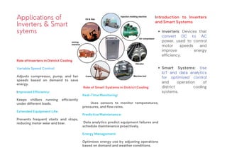
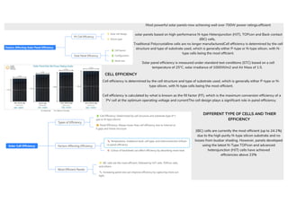
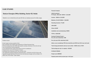
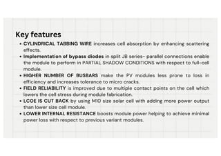
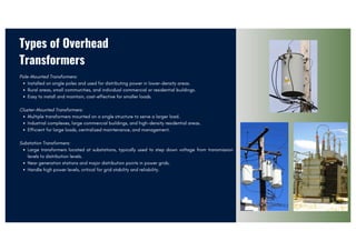
![APPLICATION
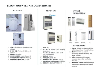
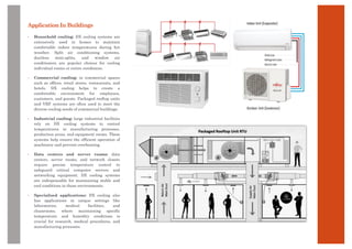
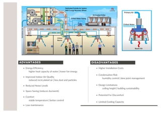
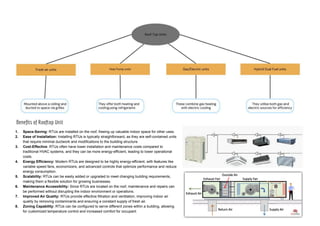
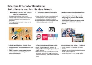
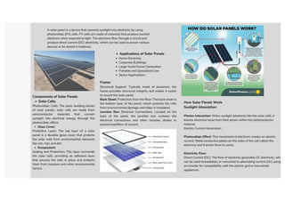
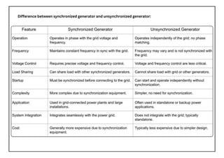
Window air conditioners are favored for their low cost, ease of maintenance compared to split A.C., and effectiveness in cooling
specific areas. Split air conditioners are popular in residential and commercial buildings for their versatility, efficiency, and ease of
installation.
03
COMMONLYUSED
ResidentialBuildings
CommercialBuildings
InstitutionalBuildings
IndustrialBuildings
HospitalityIndustry
TemporaryBuildings
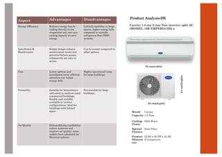
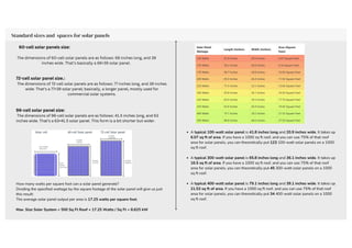
STANDARDSIZE[Brand:LG]
SplitAC:99.8x32.2x22.3cm
WindowAC: 66.6x 45x65.9cm
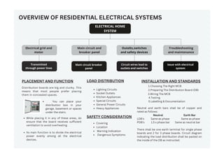
PLACEMENT(Interiors)
SplitAC:2.1to2.4m FromFFL
WindowAC: 1to1.2mFromFFL](https://image.slidesharecdn.com/pdf24merged-3-240805160233-dd26e17f/85/Building-Services-_-HVAC-ELECTRICAL-AND-LIGHTING-NOTES-5-320.jpg)


![Ar. M. Senthil [ senthilmani ], profile picture](https://cdn.slidesharecdn.com/profile-photo-senshots-48x48.jpg?cb=1727349794)
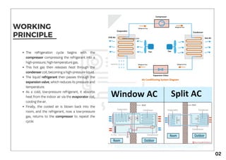
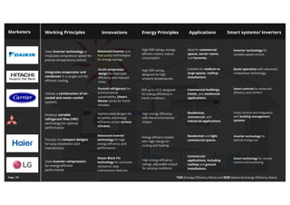
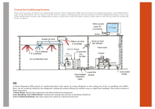
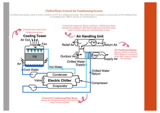
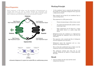
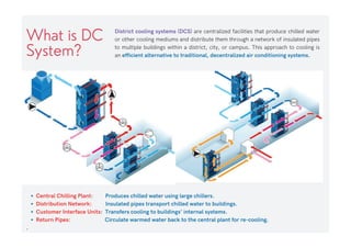
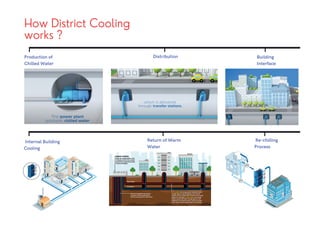
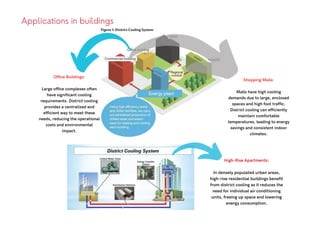
The document provides an overview of various air conditioning systems, including window, split, and cassette air conditioners, highlighting their working principles, applications, and the benefits of smart technology such as energy efficiency and remote control capabilities. It contrasts different types of air conditioners in terms of features, dimensions, and pricing, while detailing their uses in residential, commercial, and specialized environments. Additionally, the document discusses innovations like inverter technology and eco-friendly refrigerants that enhance performance and reduce environmental impact.


