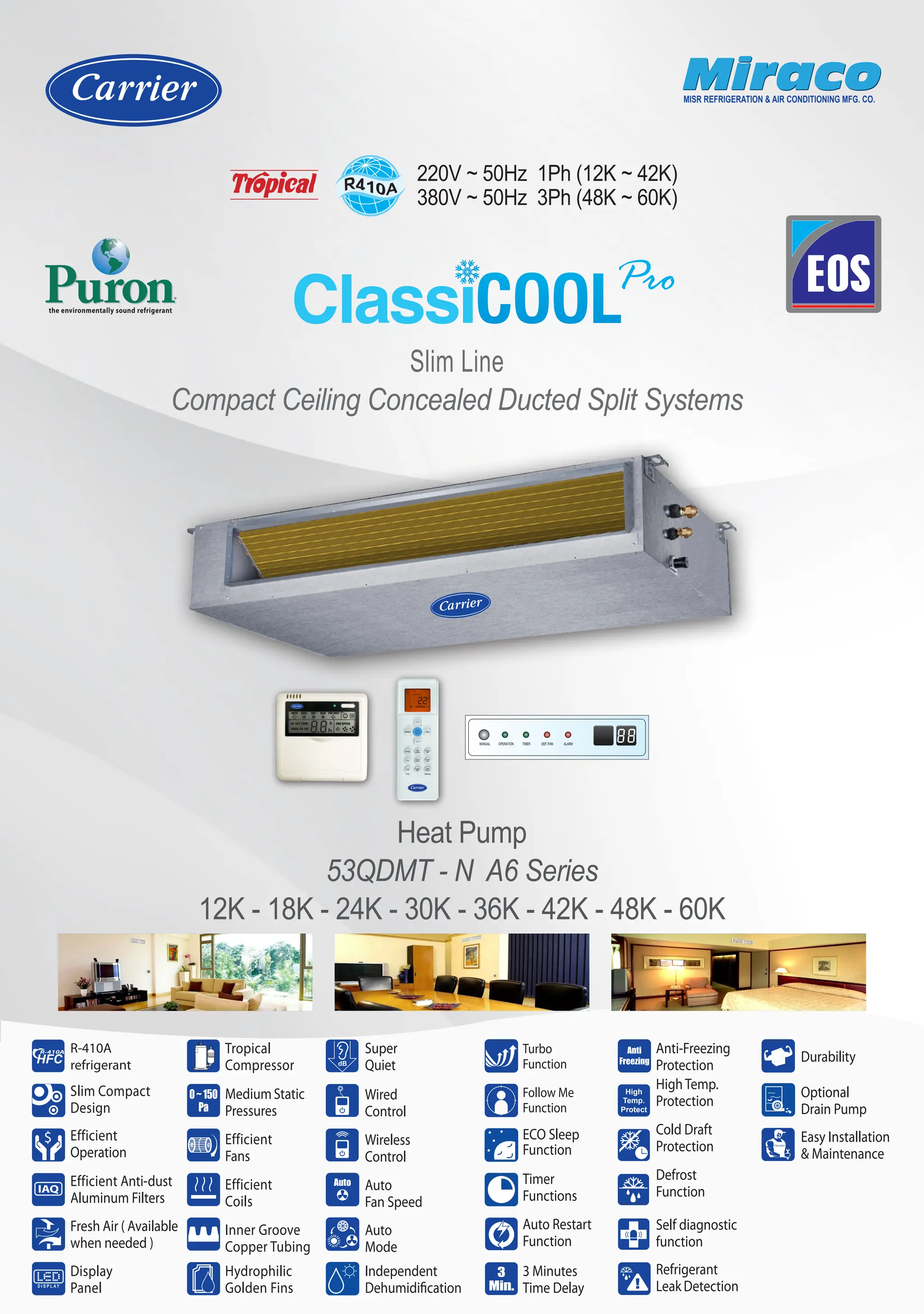
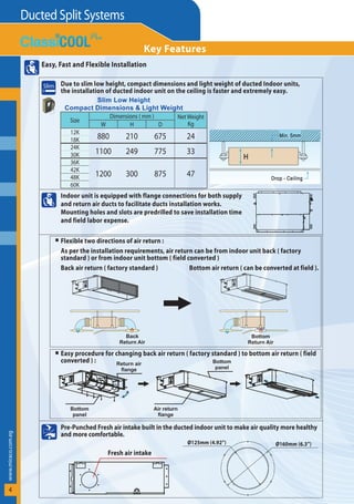
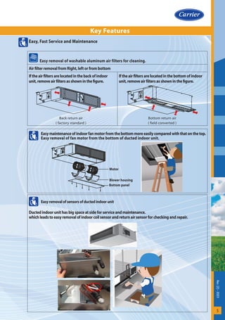
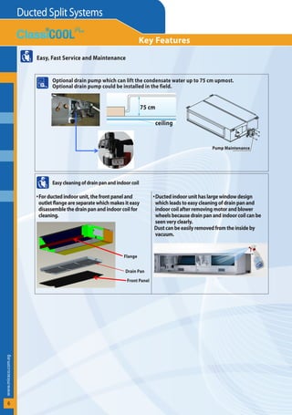
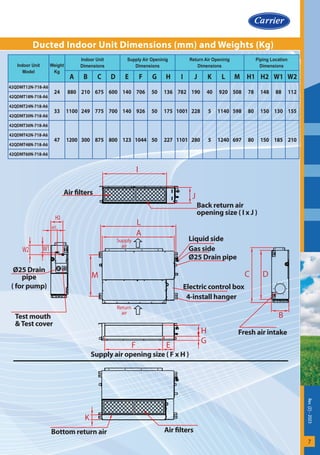
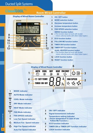
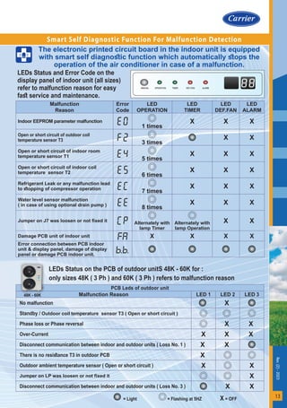
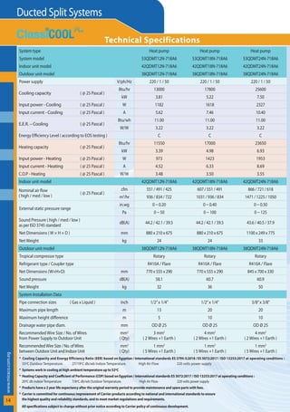
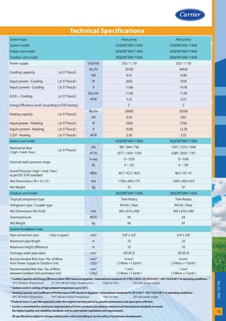
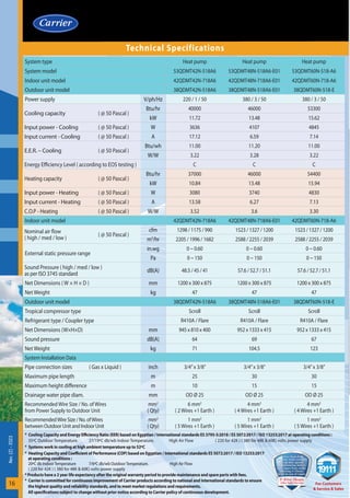
220V ~ 50Hz 1Ph (12K ~ 42K)
380V ~ 50Hz 3Ph (48K ~ 60K)
Heat Pump
53QDMT - N A6 Series
12K - 18K - 24K - 30K - 36K - 42K - 48K - 60K
Slim Line
Compact Ceiling Concealed Ducted Split Systems
Miraco
Miraco
MISR REFRIGERATION & AIR CONDITIONING MFG. CO.
the environmentally sound refrigerant
Defrost
Function
Anti-Freezing
Protection
HighTemp.
Protection
High
Temp.
Protect
Anti
Freezing
Cold Draft
Protection
Self diagnostic
function
Refrigerant
LeakDetection
Optional
Drain Pump
Durability
Easy Installation
& Maintenance
Hydrophilic
Golden Fins
Tropical
Compressor
MediumStatic
Pressures
0~150
Pa
Inner Groove
Copper Tubing
Efficient
Fans
Efficient
Coils
Wired
Control
Wireless
Control
Auto
Fan Speed
Auto
Super
Quiet
Independent
Dehumidification
Auto
Mode
Slim Compact
Design
Efficient
Operation
$
Display
Panel
Efficient Anti-dust
Aluminum Filters
IAQ
R-410A
refrigerant
R-410A
HFC
Fresh Air ( Available
when needed )
3 Minutes
Time Delay
3
Min.
Auto Restart
Function
Timer
Functions
ECO Sleep
Function
Turbo
Function
Follow Me
Function
­
w
ww.miraco.com.eg
Ducted Split Systems
2
Heat Pump
30K - 36K - 42K
12K - 18K - 24K 48K - 60K
SMART CONTROLS
OUTDOOR UNITS
mediumstaticpressure,slimline,compactdimensionsceiling
concealed ducted split is for commercial applications for the optimum air
conditioningsolutionforplaceswhichrequireceilinginstallationabovefalse
ceiling and minimum sound levels. Its slim profile and flexible installation
make this system the best choice for residential and light commercial
applications where the units are practically hidden from view.
$
EFFICIENT, TROPICAL & QUIET
Room Wired
Controller
Wireless
Remote Control
Compact invisible indoor unit with ultra slim profile and low height is
just 210 mm for sizes 12K-18K, 249 mm for sizes 24K-30K, 300 mm for
sizes 36K - 42K - 48K - 60K suitable for low false ceiling applications.
Modern Slim Design
Advanced heat transfer and aerodynamics technologies to ensure
prefect operation up to 52°C outdoor ambient temperature for
energy saving and low operating cost.
Efficient Air Management System (AMS) of blow through design
leading to maximum air flow with minimum turbulence for
minimum air resistance, smooth airflow and efficient operation.
Carrier innovative outdoor axial fan technology for efficient
operation with minimum air resistance and maximum air flow.
Carrier innovative double inlet, double width forward curved centrifugal
blower technology driven by 3 speeds high efficiency motor permanent
split capacitor type with low power consumption .
Efficient indoor and outdoor coils with large heat transfer surfaces
for minimum electrical consumption.
Efficient tropical compressor works in high ambient temperature up
to 52°C with high efficiency and low electrical consumption leading
to true powerful system cooling.
$
AMS
Smart LED display panel shows control functions and also shows error
code in case of a malfunction.
Efficient Inner grooved copper tubing compared with traditional
copper tubing, it allows more refrigerant flow, improves heat exchange
efficiency and lowers power consumption while keeping the same
capacity output level.
Precoated Hydrophilic Golden Fins of indoor and outdoor coils to
protect the coil against corrosion and to allow easy and quick removal
of unrestricted condensate water between the coil fins to increase
airflow, improve heat exchange efficiency and accelerate cooling
process and provide higher efficiency with longer life and better
corrosion resistance making it the best choice for coastal areas.
IAQ
The indoor unit is fitted with a fresh air knock out panel that can be
utilized to introduce fresh air into the room. This helps prevent the
build of stale air and enhances air quality in working environments
and enclosed applications without natural fresh air supply.
Efficient anti dust washable aluminim air filters for clean
and healthy air.
Superior air distribution performance : Three fan speeds to satisfy air
flow and static pressure requirements to suit various applications.
0~150
Pa
Healthy & Clean Indoor Air Quality (IAQ)
KEY FEATURES
Efficient Tropical Operation with
Minimum Electrical Consumption
R-410A
HFC
Works with the new R-410A refrigerant which increases its energy
efficiency and does not degrade the ozone layer.
Certified By Russian Register
Certificate Number :
20.0297.026
Occupational Health and
Safety Management System
ISO 45001 : 2018
ied By TUV
ate Number :
0296.026
ronmental
ment System
001 : 2015
Certified By DNV.GL
Certificate Number :
197044-2016-AQ-EGY-UKAS
Quality Management System
QMS ISO 9001 : 2015
Certified By Russian Register
Certificate Number :
20.0297.026
Occupational Health and
Safety Management System
ISO 45001 : 2018
Certified By TUV
Certificate Number :
20.0296.026
Environmental
Management System
ISO 14001 : 2015
By EGAC/ilac-MRA
ate Number :
40523A
nd Calibration
oratories
17025 : 2017
Certified By DNV.GL
Certificate Number :
197044-2016-AQ-EGY-UKAS
Quality Management System
QMS ISO 9001 : 2015
Certified By Russian Register
Certificate Number :
20.0297.026
Occupational Health and
Safety Management System
ISO 45001 : 2018
Certified By TUV
Certificate Number :
20.0296.026
Environmental
Management System
ISO 14001 : 2015
Accredited By EGAC/ilac-MRA
Certificate Number :
040523A
Testing and Calibration
Laboratories
ISO/IEC 17025 : 2017
Certified By DNV.GL
Certificate Number :
197044-2016-AQ-EGY-UKAS
Quality Management System
QMS ISO 9001 : 2015
ed By DNV.GL
ate Number :
16-AQ-EGY-UKAS
agement System
9001 : 2015
Rev.
(2)
-
2023
3
Standard Smart Wired Controller with complete
control functions built in the control system.
Wired Controller can be fixed on the wall and avoid
mislaying. It’s mainly used to make the control more
convenient.
Optional Smart Link central Control to monitor from
a center point, the operation of number of ducted
indoor units in the same project site.
This feature is particularly helpful in large office
applications and hotels.
Available BMS connectivity ( Building Management
System ) through BMS gateway ( BACnet, … etc. )
for Complete Control Solutions.
Standard Smart LCD infrared wireless remote
control with complete control functions built in the
control system to ensure efficiency at all operating
conditions.
ECO (sleep) function for energy saving and
comfortable healthy sleep which automatically
changes fan speed to low speed and controls both
setting and room temperatures.
Programmable timer for easy on and off selection
with energy savings including off timer,
on timer, off/on timer and on/off timer functions.
Independent Dehumidification mode which
dehumidifies the room efficiently, but not lower
the temperature so obviously as cooling operation.
Efficient centrifugal blower, new design heat
exchangers, improved Air Management System (AMS),
and quiet compressor.
Statically and dynamically balanced fans for quiet
operation.
Minimum vibrations with strengthened sheet metal
parts by finite element analysis.
Auto
Auto mode which changes automatically the
operation mode and capacity output according to
temperature difference between the room
temperature and the setting temperature.
Auto fan speed which changes automatically the fan
speed to high or medium or low fan speed by sensing
the temperature difference between the
room temperature and the setting temperature.
Smart Link
Key Features
Durability
Anti-rust, weather proof and long life indoor unit
sheet metal parts made of chemically treated and
zinc coated ( galvanized ) sheet metal.
Anti-rust, weather proof and long life outdoor unit
sheet metal parts made of chemically treated and
zinc coated ( galvanized ) sheet metal.
Powder painted casing of outdoor unit with
prefect adhesion of highly resistant ployester paint
60-80 microns thick, which is electro-statically
applied and baked at a temperature of 220°C.
Quiet with Minimum Sound Level
Complete Control Functions For Comfort
Auto restart function. When the power failure
happenes during the operation of air conditioner,
the microprocessor of the Printed Circuit Board will
operate auto restart function. After the power is
recovered, the air conditioner operates automatically
but after elapse of compressor safety time delay.
3 (three) minutes safety time delay between
compressor turning off and turning on for
compressor protection against cycling.
Anti-freezing protection of indoor coil when the air
conditioner is operating in cool mode with excessive
dirt on the indoor coil and / or clogged air filters and /
or low ambient temperature operation of cool mode.
3
Min.
Anti
Freezing
High temperature protection of outdoor coil when
the air conditioner is operating in cool mode.
Hi Temp.
Protect
Cool
Defrost function of outdoor coil when the
air conditioner is operating in heat mode
at very low ambient temperature.
Cold draft protection when the air conditioner is
operating in heat mode to prevent cold air blowing
out at the beginning of heat mode which avoids the
discomfort to the user.
Overheating Protection of indoor coil when the air
conditioner is operating in heat mode.
Overheating
Protection
Motors
Auto reset – internal thermal protector of indoor
and outdoor fan motors to protect motor windings
against excessive temperature.
Auto reset – internal overload protector of the
compressor to protect compressor motor windings
against excessive temperature.
External overload protector of compressor ( For sizes
48K – 60K 3 Phase ) to protect compressor windings
against excessive current.
Internal pressure relief valve of compressor
( For sizes 48K – 60K ) to protect compressor
against high discharge pressures.
Smart self-diagnostic function for malfunctions
detection for easy fast service and maintenance.
Smart Refrigerant leak detection by sensitive
sensor mounted on indoor coil for easy fast service
and maintenance.
The components of both indoor and outdoor units
comply with international standards of performance
and safety.
Complete Protection Functions for Safety & Reliability
Smart Link
BMS
Turbo function which automatically changes the fan
speed to maximum speed to maximize the cooling
capacity output to cool down the room rapidly and to
attain the desired temperature in the shortest time.
Through wireless remote control.
Follow Me function for smart control of comfortable
temperature. With this technology, an efficient
temperature sensor is built in the wired controller or
wireless remote controller just like the air conditioner is
following wired controller or wireless remote controller.
­
w
ww.miraco.com.eg
Ducted Split Systems
4
Key Features
Min. 5mm
Drop - Ceiling
H
Slim Low Height
Compact Dimensions & Light Weight
Easy, Fast and Flexible Installation
Due to slim low height, compact dimensions and light weight of ducted Indoor units,
the installation of ducted indoor unit on the ceiling is faster and extremely easy.
Indoor unit is equipped with flange connections for both supply
and return air ducts to facilitate ducts installation works.
Mounting holes and slots are predrilled to save installation time
and field labor expense.
Flexible two directions of air return :
As per the installation requirements, air return can be from indoor unit back ( factory
standard ) or from indoor unit bottom ( field converted )
Back air return ( factory standard ) Bottom air return ( can be converted at field ).
Easy procedure for changing back air return ( factory standard ) to bottom air return ( field
converted ) :
Pre-Punched Fresh air intake built in the ducted indoor unit to make air quality more healthy
and more comfortable.
Back
Return Air
Bottom
Return Air
Return air
flange
Air return
flange
Bottom
panel
Bottom
panel
Fresh air intake
Ø160mm (6.3”)
Ø125mm (4.92”)
Size
Dimensions ( mm ) Net Weight
Kg
W H D
12K
880 210 675 24
18K
24K
1100 249 775 33
30K
36K
1200 300 875 47
42K
48K
60K
Rev.
(2)
-
2023
5
Key Features
Easy, Fast Service and Maintenance
Easy removal of washable aluminum air filters for cleaning.
Air filter removal from Right, left or from bottom
Iftheairfiltersarelocatedinthebackofindoor
unit,removeairfiltersasshowninthefigure.
Iftheairfiltersarelocatedinthebottomofindoor
unit,removeairfiltersasshowninthefigure.
Easymaintenanceofindoorfanmotorfromthebottommoreeasilycomparedwiththatonthetop.
Easy removal of fan motor from the bottom of ducted indoor unit.
Easyremovalofsensorsofductedindoorunit
Ducted indoor unit has big space at side for service and maintenance.
which leads to easy removal of indoor coil sensor and return air sensor for checking and repair.
Back return air
( factory standard )
Bottom return air
( field converted )
Motor
Blower housing
Bottom panel
­
w
ww.miraco.com.eg
Ducted Split Systems
6
Key Features
Easy, Fast Service and Maintenance
Optional drain pump which can lift the condensate water up to 75 cm upmost.
Optional drain pump could be installed in the field.
Easycleaningofdrainpanandindoorcoil
For ducted indoor unit, the front panel and
outlet flange are separate which makes it easy
disassemble the drain pan and indoor coil for
cleaning.
Ducted indoor unit has large window design
which leads to easy cleaning of drain pan and
indoor coil after removing motor and blower
wheels because drain pan and indoor coil can be
seen very clearly.
Dust can be easily removed from the inside by
vacuum.
75 cm
ceiling
Flange
Drain Pan
Front Panel
Pump Maintenance
Rev.
(2)
-
2023
7
Ducted Indoor Unit Dimensions (mm) and Weights (Kg)
Indoor Unit
Model
Weight
Kg
Indoor Unit
Dimensions
Supply Air Openinig
Dimensions
Return Air Openinig
Dimensions
Piping Location
Dimensions
A B C D E F G H I J K L M H1 H2 W1 W2
42QDMT12N-718-A6
24 880 210 675 600 140 706 50 136 782 190 40 920 508 78 148 88 112
42QDMT18N-718-A6
42QDMT24N-718-A6
33 1100 249 775 700 140 926 50 175 1001 228 5 1140 598 80 150 130 155
42QDMT30N-718-A6
42QDMT36N-718-A6
47 1200 300 875 800 123 1044 50 227 1101 280 5 1240 697 80 150 185 210
42QDMT42N-718-A6
42QDMT48N-718-A6
42QDMT60N-718-A6
Supply air opening size ( F x H )
Fresh air intake
Test mouth
&Test cover
4-install hanger
Ø25 Drain pipe
Gas side
Liquid side
Electric control box
A
M
L
F E
G
H
B
D
C
Ø25 Drain
pipe
( for pump)
W1
W2
H1
H2
H2
Supply
air
Return
air
Air filters
Bottom return air
K
Air filters
Back return air
opening size ( I x J )
I
J
­
w
ww.miraco.com.eg
Ducted Split Systems
8
Room Wired Controller
4
5
6
1
7
8
9
10
12
11
13
3
2
Display of Wired Room Controller 1 ON / OFF button
2 MODE selection button
3 Decrease temperature button
4 Increase temperature button
5 FAN SPEED selection button
6
SWING function button
( This function does not work with ducted
indoor units but works with other indoor types )
7 ECO function button
8 FOLLOW ME function button
9 TIMER ON function button
10 TIMER OFF function button
11
AUXIL HEATER function button
( This function does not work with ducted
indoor units but works with other indoor types )
12 LOCK function button
13 RESET function button
Display of Wired Room Controller
AUTO
Auto
TIMER ON OFF
SET TEMP.
H
L M
COOL DRY HEAT FAN ONLY
FAN SPEED
1
2
3
6
5
4
7
8
MODE indicator
1
AUTO Mode indicator
AUTO
Auto
COOL Mode indicator
COOL
DRY Mode indicator
DRY
HEAT Mode indicator
HEAT
FAN Mode indicator
FAN ONLY
FAN SPEED indicator
2
Low Fan Speed indicator
L
Medium Fan Speed indicator
M
High Fan Speed indicator
H
Auto Fan Speed indicator
ON / OFF indicator
3
Signal transmission indicator
4
Temperature setting indicator
( Room temperature in case of use
Follow Me Function )
5
ECO function indicator
6
TIMER ON or TIMER OFF function indicator
7
LOCK function indicator
8
Rev.
(2)
-
2023
9
Wireless Remote Control
Display of
Remote Control
Signal transmission indicator
1
Operation MODE indicator
2
Automatic
Cooling
Dehumidification only
Heating
Ventilation (fan only)
ON / OFF indicator
3
SET TEMP. indicator
4
FAN SPEED indicator
5
Low FAN SPEED indicator
Medium FAN SPEED indicator
High FAN SPEED indicator
Automatic FAN SPEED indicator
TIMER ON function indicator
6
TIMER OFF function indicator
7
FOLLOW ME function indicator
8
Sleep function indicator
9
LOCK function indicator
10
Batteries exhausted indicator
11
Control Buttons
MODE selection button
AUTO - COOL - DRY - HEAT - FAN
1
Decrease temperature button
Each time you press the button, the temperature decreased by 1°C
2
Increase temperature button
Each time you press the button, the temperature increased by 1°C
3
FAN selection button
High - Medium - Low - Auto fan speed
4
ON/OFF button
5
Louvers Auto Swing button *
Press more than 2 seconds, louver will swing up and down automatically
6
Louvers position button *
Press less than 2 seconds to change louver position 6 degree up and down
7
ECO Sleep function button
8
TIMER OFF function button
9
TIMER ON function button
10
My Mode function button to memorize the
preferred settings
11
Panel LED display on/off function button
12
Fresh air function button *
Follow Me function button (Basedonremotecontrolsensor)
13
TURBO High Power function button
14
Self Clean function button *
Note : * This function does not work with this product
but works with other products
Display of Selected Functions
1
5
2
6
7
8
12
13
9
11
10
5
7
4
6
8
2
1 3
10
9
14
3
4
11
­
w
ww.miraco.com.eg
Ducted Split Systems
10
Air Flow Versus External Static Pressure
42QDMT12N-718A6
ESP
in.wg 0 0.10 0.20
Pa 0 25 50
Air Flow
cfm cfm cfm
m3
/h m3
/h m3
/h
High Speed
623 551 481
1058 936 817
Medium Speed
545 491 429
926 834 729
Low Speed
480 425 362
816 722 615
42QDMT18N-718A6
ESP
in.wg 0 0.10 0.20 0.30 0.40
Pa 0 25 50 75 100
Air Flow
cfm cfm cfm cfm cfm
m3
/h m3
/h m3
/h m3
/h m3
/h
High Speed
688 607 521 420 280
1169 1031 885 714 476
Medium Speed
623 551 481 383 253
1058 936 817 651 430
Low Speed
545 491 429 293 179
926 834 729 498 304
42QDMT24N-718A6
ESP
in.wg 0 0.10 0.20 0.30 0.40 0.50
Pa 0 25 50 75 100 125
Air Flow
cfm cfm cfm cfm cfm cfm
m3
/h m3
/h m3
/h m3
/h m3
/h m3
/h
High Speed
874 866 835 795 746 697
1485 1471 1419 1351 1267 1184
Medium Speed
735 721 694 661 569 477
1249 1225 1179 1123 967 810
Low Speed
638 618 591 555 473 391
1084 1050 1004 943 804 664
42QDMT30N-718A6
ESP
in.wg 0 0.10 0.15 0.20 0.30 0.40 0.50
Pa 0 25 37 50 75 100 125
Air Flow
cfm cfm cfm cfm cfm cfm cfm
m3
/h m3
/h m3
/h m3
/h m3
/h m3
/h m3
/h
High Speed
1087 1017 987 951 877 779 681
1847 1728 1677 1616 1490 1324 1157
Medium Speed
936 873 844 815 755 678 601
1590 1483 1434 1385 1283 1152 1021
Low Speed
817 758 736 707 648 578 508
1388 1288 1250 1201 1101 982 863
Rev.
(2)
-
2023
11
Air Flow Versus External Static Pressure
42QDMT36N-718A6
ESP
in.wg 0 0.10 0.15 0.20 0.30 0.40 0.50 0.60
Pa 0 25 37 50 75 100 125 150
Air Flow
cfm cfm cfm cfm cfm cfm cfm cfm
m3
/h m3
/h m3
/h m3
/h m3
/h m3
/h m3
/h m3
/h
High Speed
1464 1376 1347 1298 1135 1042 905 758
2487 2338 2289 2205 1928 1770 1538 1288
Medium Speed
1290 1230 1210 1175 1035 930 850 670
2192 2090 2056 1996 1758 1580 1444 1138
Low Speed
1140 1070 1040 990 885 780 645 522
1937 1818 1767 1682 1504 1325 1096 887
42QDMT42N-718A6
ESP
in.wg 0 0.10 0.15 0.20 0.30 0.40 0.50 0.60
Pa 0 25 37 50 75 100 125 150
Air Flow
cfm cfm cfm cfm cfm cfm cfm cfm
m3
/h m3
/h m3
/h m3
/h m3
/h m3
/h m3
/h m3
/h
High Speed
1464 1376 1347 1298 1135 1042 905 758
2487 2338 2289 2205 1928 1770 1538 1288
Medium Speed
1290 1230 1210 1175 1035 930 850 670
2192 2090 2056 1996 1758 1580 1444 1138
Low Speed
1140 1070 1040 990 885 780 645 522
1937 1818 1767 1682 1504 1325 1096 887
42QDMT48N-718A6-E01
ESP
in.wg 0 0.10 0.15 0.20 0.30 0.40 0.50 0.60
Pa 0 25 37 50 75 100 125 150
Air Flow
cfm cfm cfm cfm cfm cfm cfm cfm
m3
/h m3
/h m3
/h m3
/h m3
/h m3
/h m3
/h m3
/h
High Speed
1667 1593 1564 1523 1442 1346 1135 981
2832 2707 2657 2588 2450 2287 1928 1667
Medium Speed
1468 1400 1363 1327 1251 1135 1045 872
2494 2379 2316 2255 2125 1928 1775 1482
Low Speed
1297 1242 1218 1200 1078 961 830 703
2204 2110 2069 2039 1832 1633 1410 1194
42QDMT60N-718-A6
ESP
in.wg 0 0.10 0.15 0.20 0.30 0.40 0.50 0.60
Pa 0 25 37 50 75 100 125 150
Air Flow
cfm cfm cfm cfm cfm cfm cfm cfm
m3
/h m3
/h m3
/h m3
/h m3
/h m3
/h m3
/h m3
/h
High Speed
1667 1593 1564 1523 1442 1346 1135 981
2832 2707 2657 2588 2450 2287 1928 1667
Medium Speed
1468 1400 1363 1327 1251 1135 1045 872
2494 2379 2316 2255 2125 1928 1775 1482
Low Speed
1297 1242 1218 1200 1078 961 830 703
2204 2110 2069 2039 1832 1633 1410 1194
­
w
ww.miraco.com.eg
Ducted Split Systems
12
1 MANUAL Button
* This button is used to operate the unit temporarily during maintenance/repair operations.
* Once you push temporary button, the air conditioner will run in such order:
Auto, Forced cool, off and back to Auto
AUTO
The OPERATION lamp is lit, and the air conditioner will run under AUTO mode.
FORCED COOL
The OPERATION lamp flashes, the air conditioner will turn to AUTO after it is enforced to
cool with a wind speed of HIGH for 30 minutes. The remote controller operation is disabled.
OFF
The OPERATION lamp goes off. The air conditioner is OFF while the remote controller
operation is enabled.
2 OPERATION green led
* OPERATION green led lights on when the air conditioner operates
* OPERATION green led lights off when the air conditioner stops
3 TIMER green led
* TIMER green led lights on when timer function operates
* TIMER green led lights off when timer function stops
4 DEF. / FAN red led
This led lights on when defrost protection is activated and lights off
when defrost protection terminates in heat mode.
5 ALARM red led
ALARM red led flashes when there is a malfunction in outdoor unit
6 Infrared Signal Receiver
( In case of using wireless remote control )
7 Digital Display
This display shows error code in case of a malfunction.
Display Panel
6
5
4
3
2
1 7
Rev.
(2)
-
2023
13
Smart Self Diagnostic Function For Malfunction Detection
The electronic printed circuit board in the indoor unit is equipped
with smart self diagnostic function which automatically stops the
operation of the air conditioner in case of a malfunction.
PCB Leds of outdoor unit
Malfunction Reason LED 1 LED 2 LED 3
No malfunction X
Standby / Outdoor coil temperature sensor T3 ( Open or short circuit )
Phase loss or Phase reversal X X
Over-Current X X X
Disconnect communication between indoor and outdoor units ( Loss No. 1 ) X X
There is no resistance T3 in outdoor PCB X
Outdoor ambient temperature sensor ( Open or short circuit ) X X
Jumper on LP was loosen or not fixed it X
Disconnect communication between indoor and outdoor units ( Loss No. 3 ) X X
= Light = Flashing at 5HZ X = OFF
LEDs Status and Error Code on the
display panel of indoor unit (all sizes)
refer to malfunction reason for easy
fast service and maintenance.
LEDs Status on the PCB of outdoor unitS 48K - 60K for :
only sizes 48K ( 3 Ph ) and 60K ( 3 Ph ) refers to malfunction reason
Malfunction
Reason
Error
Code
LED
OPERATION
LED
TIMER
LED
DEF.FAN
LED
ALARM
Indoor EEPROM parameter malfunction
1 times
X X X
Open or short circuit of outdoor coil
temperature sensor T3
3 times
X X
Open or short circuit of indoor room
temperature sensor T1
5 times
X X X
Open or short circuit of indoor coil
temperature sensor T2
6 times
X X X
Refrigerant Leak or any malfunction lead
to stopping of compressor operation
7 times
X X X
Water level sensor malfunction
( in case of using optional drain pump )
8 times
X X X
Jumper on J7 was loosen or not fixed it Alternately with
lamp Timer
Alternately with
lamp Operation
X X
Damage PCB unit of indoor unit
FA X X X X
Error connection between PCB indoor
unit & display panel, damage of display
panel or damage PCB indoor unit.
. .
48K - 60K
­
w
ww.miraco.com.eg
Ducted Split Systems
14
System type Heat pump Heat pump Heat pump
System model 53QDMT12N-718A6 53QDMT18N-718A6 53QDMT24N-718A6
Indoor unit model 42QDMT12N-718A6 42QDMT18N-718A6 42QDMT24N-718A6
Outdoor unit model 38QDMT12N-718A6 38QDMT18N-718A6 38QDMT24N-718A6
Power supply V/ph/Hz 220 / 1 / 50 220 / 1 / 50 220 / 1 / 50
Cooling capacity ( @ 25 Pascal )
Btu/hr 13000 17800 25600
kW 3.81 5.22 7.50
Input power - Cooling ( @ 25 Pascal ) W 1182 1618 2327
Input current - Cooling ( @ 25 Pascal ) A 5.62 7.46 10.40
E.E.R. – Cooling ( @ 25 Pascal )
Btu/wh 11.00 11.00 11.00
W/W 3.22 3.22 3.22
Energy Efficiency Level ( according to EOS testing ) C C C
Heating capacity ( @ 25 Pascal )
Btu/hr 11550 17000 23650
kW 3.39 4.98 6.93
Input power - Heating ( @ 25 Pascal ) W 973 1423 1953
Input current - Heating ( @ 25 Pascal ) A 4.52 6.33 8.69
C.O.P - Heating ( @ 25 Pascal ) W/W 3.48 3.50 3.55
Indoor unit model 42QDMT12N-718A6 42QDMT18N-718A6 42QDMT24N-718A6
Nominal air flow
( high / med / low )
( @ 25 Pascal )
cfm 551 / 491 / 425 607 / 551 / 491 866 / 721 / 618
m3
/hr 936 / 834 / 722 1031 / 936 / 834 1471 / 1225 / 1050
External static pressure range
in.wg 0 ~ 0.20 0 ~ 0.40 0 ~ 0.50
Pa 0 ~ 50 0 ~ 100 0 ~ 125
Sound Pressure ( high / med / low )
as per ISO 3745 standard
dB(A) 44.2 / 42.1 / 39.5 44.2 / 42.1 / 39.5 43.6 / 40.5 / 37.9
Net Dimensions ( W × H × D ) mm 880 x 210 x 675 880 x 210 x 675 1100 x 249 x 775
Net Weight kg 24 24 33
Outdoor unit model 38QDMT12N-718A6 38QDMT18N-718A6 38QDMT24N-718A6
Tropical compressor type Rotary Rotary Rotary
Refrigerant type / Coupler type R410A / Flare R410A / Flare R410A / Flare
Net Dimensions (W×H×D) mm 770 x 555 x 290 770 x 555 x 290 845 x 700 x 330
Sound pressure dB(A) 58.1 60.7 60.9
Net Weight kg 32 36 50
System Installation Data
Pipe connection sizes ( Gas x Liquid ) inch 1/2”x 1/4” 1/2”x 1/4” 5/8”x 3/8”
Maximum pipe length m 13 20 20
Maximum height difference m 5 10 10
Drainage water pipe diam. mm OD Ø 25 OD Ø 25 OD Ø 25
Recommended Wire Size / No. of Wires
from Power Supply to Outdoor Unit
mm2
( Qty)
3 mm2
( 2 Wires +1 Earth )
4 mm2
( 2 Wires +1 Earth )
4 mm2
( 2 Wires +1 Earth )
RecommendedWire Size / No. ofWires
between Outdoor Unit and Indoor Unit
mm2
( Qty)
1 mm2
( 5 Wires +1 Earth )
1 mm2
( 5 Wires +1 Earth )
1 mm2
( 5 Wires +1 Earth )
* Cooling Capacity and Energy Efficiency Ratio (EER) based on Egyptian / International standards ES 3795-5:2018 / ES 5072:2017 / ISO 13253:2017 at operating conditions :
35ºC Outdoor Temperature. 27/19ºC db/wb Indoor Temperature. High Air Flow 220 volts power supply
* Systems work in cooling at high ambient temperature up to 52ºC
* Heating Capacity and Coefficient of Performance (COP) based on Egyptian / International standards ES 5072:2017 / ISO 13253:2017 at operating conditions :
20ºC db IndoorTemperature 7/6ºC db/wb OutdoorTemperature. High Air Flow 220 volts power supply
* Products have a 2 year life expectancy after the original warranty period to provide maintenance and spare parts with fees.
* Carrier is committed for continuous improvement of Carrier products according to national and international standards to ensure
the highest quality and reliability standards, and to meet market regulations and requirements.
All specifications subject to change without prior notice according to Carrier policy of continuous development.
Technical Specifications
Rev.
(2)
-
2023
15
Technical Specifications
System type Heat pump Heat pump
System model 53QDMT30N-718A6 53QDMT36N-718A6
Indoor unit model 42QDMT30N-718A6 42QDMT36N-718A6
Outdoor unit model 38QDMT30N-718A6 38QDMT36N-718A6
Power supply V/ph/Hz 220 / 1 / 50 220 / 1 / 50
Cooling capacity ( @ 37 Pascal )
Btu/hr 29100 36950
kW 8.53 10.83
Input power - Cooling ( @ 37 Pascal ) W 2645 3359
Input current - Cooling ( @ 37 Pascal ) A 11.68 14.78
E.E.R. – Cooling ( @ 37 Pascal )
Btu/wh 11.00 11.00
W/W 3.22 3.22
Energy Efficiency Level ( according to EOS testing ) C C
Heating capacity ( @ 37 Pascal )
Btu/hr 29000 33500
kW 8.50 9.82
Input power - Heating ( @ 37 Pascal ) W 2428 2766
Input current - Heating ( @ 37 Pascal ) A 10.80 12.28
C.O.P - Heating ( @ 37 Pascal ) W/W 3.50 3.55
Indoor unit model 42QDMT30N-718A6 42QDMT36N-718A6
Nominal air flow
( high / med / low )
( @ 37 Pascal )
cfm 987 / 844 / 736 1347 / 1210 / 1040
m3
/hr 1677 / 1434 / 1250 2289 / 2056 / 1767
External static pressure range
in.wg 0 ~ 0.50 0 ~ 0.60
Pa 0 ~ 125 0 ~ 150
Sound Pressure ( high / med / low )
as per ISO 3745 standard
dB(A) 48.7 / 42.5 / 40.9 48.5 / 45 / 41
Net Dimensions ( W × H × D ) mm 1100 x 249 x 775 1200 x 300 x 875
Net Weight kg 33 47
Outdoor unit model 38QDMT30N-718A6 38QDMT36N-718A6
Tropical compressor type Twin Rotary Twin Rotary
Refrigerant type / Coupler type R410A / Flare R410A / Flare
Net Dimensions (W×H×D) mm 945 x 810 x 400 945 x 810 x 400
Sound pressure dB(A) 64 64
Net Weight kg 66 67
System Installation Data
Pipe connection sizes ( Gas x Liquid ) inch 5/8”x 3/8” 3/4”x 3/8”
Maximum pipe length m 25 25
Maximum height difference m 10 10
Drainage water pipe diam. mm OD Ø 25 OD Ø 25
Recommended Wire Size / No. of Wires
from Power Supply to Outdoor Unit
mm2
( Qty)
6 mm2
( 2 Wires +1 Earth )
6 mm2
( 2 Wires +1 Earth )
RecommendedWire Size / No. ofWires
between Outdoor Unit and Indoor Unit
mm2
( Qty)
1 mm2
( 5 Wires +1 Earth )
1 mm2
( 5 Wires +1 Earth )
* Cooling Capacity and Energy Efficiency Ratio (EER) based on Egyptian / International standards ES 3795-5:2018 / ES 5072:2017 / ISO 13253:2017 at operating conditions :
35ºC Outdoor Temperature. 27/19ºC db/wb Indoor Temperature. High Air Flow 220 volts power supply
* Systems work in cooling at high ambient temperature up to 52ºC
* Heating Capacity and Coefficient of Performance (COP) based on Egyptian / International standards ES 5072:2017 / ISO 13253:2017 at operating conditions :
20ºC db IndoorTemperature 7/6ºC db/wb OutdoorTemperature. High Air Flow 220 volts power supply
* Products have a 2 year life expectancy after the original warranty period to provide maintenance and spare parts with fees.
* Carrier is committed for continuous improvement of Carrier products according to national and international standards to ensure
the highest quality and reliability standards, and to meet market regulations and requirements.
All specifications subject to change without prior notice according to Carrier policy of continuous development.
Rev.
(2)
-
2023
16
Technical Specifications
System type Heat pump Heat pump Heat pump
System model 53QDMT42N-518A6 53QDMT48N-518A6-E01 53QDMT60N-518-A6
Indoor unit model 42QDMT42N-718A6 42QDMT48N-718A6-E01 42QDMT60N-718-A6
Outdoor unit model 38QDMT42N-518A6 38QDMT48N-518A6-E01 38QDMT60N-518-E
Power supply V/ph/Hz 220 / 1 / 50 380 / 3 / 50 380 / 3 / 50
Cooling capacity ( @ 50 Pascal )
Btu/hr 40000 46000 53300
kW 11.72 13.48 15.62
Input power - Cooling ( @ 50 Pascal ) W 3636 4107 4845
Input current - Cooling ( @ 50 Pascal ) A 17.12 6.59 7.14
E.E.R. – Cooling ( @ 50 Pascal )
Btu/wh 11.00 11.20 11.00
W/W 3.22 3.28 3.22
Energy Efficiency Level ( according to EOS testing ) C C C
Heating capacity ( @ 50 Pascal )
Btu/hr 37000 46000 54400
kW 10.84 13.48 15.94
Input power - Heating ( @ 50 Pascal ) W 3080 3740 4830
Input current - Heating ( @ 50 Pascal ) A 13.58 6.27 7.13
C.O.P - Heating ( @ 50 Pascal ) W/W 3.52 3.6 3.30
Indoor unit model 42QDMT42N-718A6 42QDMT48N-718A6-E01 42QDMT60N-718-A6
Nominal air flow
( high / med / low )
( @ 50 Pascal )
cfm 1298 / 1175 / 990 1523 / 1327 / 1200 1523 / 1327 / 1200
m3
/hr 2205 / 1996 / 1682 2588 / 2255 / 2039 2588 / 2255 / 2039
External static pressure range
in.wg 0 ~ 0.60 0 ~ 0.60 0 ~ 0.60
Pa 0 ~ 150 0 ~ 150 0 ~ 150
Sound Pressure ( high / med / low )
as per ISO 3745 standard
dB(A) 48.5 / 45 / 41 57.6 / 52.7 / 51.1 57.6 / 52.7 / 51.1
Net Dimensions ( W × H × D ) mm 1200 x 300 x 875 1200 x 300 x 875 1200 x 300 x 875
Net Weight kg 47 47 47
Outdoor unit model 38QDMT42N-518A6 38QDMT48N-518A6-E01 38QDMT60N-518-E
Tropical compressor type Scroll Scroll Scroll
Refrigerant type / Coupler type R410A / Flare R410A / Flare R410A / Flare
Net Dimensions (W×H×D) mm 945 x 810 x 400 952 x 1333 x 415 952 x 1333 x 415
Sound pressure dB(A) 64 69 67
Net Weight kg 71 104.5 123
System Installation Data
Pipe connection sizes ( Gas x Liquid ) inch 3/4”x 3/8” 3/4”x 3/8” 3/4”x 3/8”
Maximum pipe length m 25 30 30
Maximum height difference m 10 15 15
Drainage water pipe diam. mm OD Ø 25 OD Ø 25 OD Ø 25
Recommended Wire Size / No. of Wires
from Power Supply to Outdoor Unit
mm2
( Qty)
6 mm2
( 2 Wires +1 Earth )
4 mm2
( 4 Wires +1 Earth )
4 mm2
( 4 Wires +1 Earth )
RecommendedWire Size / No. ofWires
between Outdoor Unit and Indoor Unit
mm2
( Qty)
1 mm2
( 5 Wires +1 Earth )
1 mm2
( 5 Wires +1 Earth )
1 mm2
( 5 Wires +1 Earth )
* Cooling Capacity and Energy Efficiency Ratio (EER) based on Egyptian / International standards ES 3795-5:2018 / ES 5072:2017 / ISO 13253:2017 at operating conditions :
35ºC Outdoor Temperature. 27/19ºC db/wb Indoor Temperature. High Air Flow ( 220 for 42K ) ( 380 for 48K & 60K) volts power supply
* Systems work in cooling at high ambient temperature up to 52ºC
* Heating Capacity and Coefficient of Performance (COP) based on Egyptian / International standards ES 5072:2017 / ISO 13253:2017
at operating conditions :
20ºC db IndoorTemperature 7/6ºC db/wb OutdoorTemperature. High Air Flow
( 220 for 42K ) ( 380 for 48K & 60K) volts power supply
* Products have a 2 year life expectancy after the original warranty period to provide maintenance and spare parts with fees.
* Carrier is committed for continuous improvement of Carrier products according to national and international standards to ensure
the highest quality and reliability standards, and to meet market regulations and requirements.
All specifications subject to change without prior notice according to Carrier policy of continuous development.
For Customers
& Service & Sales
19111
1
9
1
1
1 5 (Five )Years
After Sales Service
2
2 (Two) Years Full
(Two) Years Full
Warranty from customer
receipt date against
manufacturing defects
Free Spare Parts in the
following
following 3
3 (Three)
(Three)
Years in case of repair

كتالوج تكييف كاريير كونسيلد انجليزي.pdfuj

  • 1.
    220V ~ 50Hz1Ph (12K ~ 42K) 380V ~ 50Hz 3Ph (48K ~ 60K) Heat Pump 53QDMT - N A6 Series 12K - 18K - 24K - 30K - 36K - 42K - 48K - 60K Slim Line Compact Ceiling Concealed Ducted Split Systems Miraco Miraco MISR REFRIGERATION & AIR CONDITIONING MFG. CO. the environmentally sound refrigerant Defrost Function Anti-Freezing Protection HighTemp. Protection High Temp. Protect Anti Freezing Cold Draft Protection Self diagnostic function Refrigerant LeakDetection Optional Drain Pump Durability Easy Installation & Maintenance Hydrophilic Golden Fins Tropical Compressor MediumStatic Pressures 0~150 Pa Inner Groove Copper Tubing Efficient Fans Efficient Coils Wired Control Wireless Control Auto Fan Speed Auto Super Quiet Independent Dehumidification Auto Mode Slim Compact Design Efficient Operation $ Display Panel Efficient Anti-dust Aluminum Filters IAQ R-410A refrigerant R-410A HFC Fresh Air ( Available when needed ) 3 Minutes Time Delay 3 Min. Auto Restart Function Timer Functions ECO Sleep Function Turbo Function Follow Me Function
  • 2.
    ­ w ww.miraco.com.eg Ducted Split Systems 2 HeatPump 30K - 36K - 42K 12K - 18K - 24K 48K - 60K SMART CONTROLS OUTDOOR UNITS mediumstaticpressure,slimline,compactdimensionsceiling concealed ducted split is for commercial applications for the optimum air conditioningsolutionforplaceswhichrequireceilinginstallationabovefalse ceiling and minimum sound levels. Its slim profile and flexible installation make this system the best choice for residential and light commercial applications where the units are practically hidden from view. $ EFFICIENT, TROPICAL & QUIET Room Wired Controller Wireless Remote Control Compact invisible indoor unit with ultra slim profile and low height is just 210 mm for sizes 12K-18K, 249 mm for sizes 24K-30K, 300 mm for sizes 36K - 42K - 48K - 60K suitable for low false ceiling applications. Modern Slim Design Advanced heat transfer and aerodynamics technologies to ensure prefect operation up to 52°C outdoor ambient temperature for energy saving and low operating cost. Efficient Air Management System (AMS) of blow through design leading to maximum air flow with minimum turbulence for minimum air resistance, smooth airflow and efficient operation. Carrier innovative outdoor axial fan technology for efficient operation with minimum air resistance and maximum air flow. Carrier innovative double inlet, double width forward curved centrifugal blower technology driven by 3 speeds high efficiency motor permanent split capacitor type with low power consumption . Efficient indoor and outdoor coils with large heat transfer surfaces for minimum electrical consumption. Efficient tropical compressor works in high ambient temperature up to 52°C with high efficiency and low electrical consumption leading to true powerful system cooling. $ AMS Smart LED display panel shows control functions and also shows error code in case of a malfunction. Efficient Inner grooved copper tubing compared with traditional copper tubing, it allows more refrigerant flow, improves heat exchange efficiency and lowers power consumption while keeping the same capacity output level. Precoated Hydrophilic Golden Fins of indoor and outdoor coils to protect the coil against corrosion and to allow easy and quick removal of unrestricted condensate water between the coil fins to increase airflow, improve heat exchange efficiency and accelerate cooling process and provide higher efficiency with longer life and better corrosion resistance making it the best choice for coastal areas. IAQ The indoor unit is fitted with a fresh air knock out panel that can be utilized to introduce fresh air into the room. This helps prevent the build of stale air and enhances air quality in working environments and enclosed applications without natural fresh air supply. Efficient anti dust washable aluminim air filters for clean and healthy air. Superior air distribution performance : Three fan speeds to satisfy air flow and static pressure requirements to suit various applications. 0~150 Pa Healthy & Clean Indoor Air Quality (IAQ) KEY FEATURES Efficient Tropical Operation with Minimum Electrical Consumption R-410A HFC Works with the new R-410A refrigerant which increases its energy efficiency and does not degrade the ozone layer. Certified By Russian Register Certificate Number : 20.0297.026 Occupational Health and Safety Management System ISO 45001 : 2018 ied By TUV ate Number : 0296.026 ronmental ment System 001 : 2015 Certified By DNV.GL Certificate Number : 197044-2016-AQ-EGY-UKAS Quality Management System QMS ISO 9001 : 2015 Certified By Russian Register Certificate Number : 20.0297.026 Occupational Health and Safety Management System ISO 45001 : 2018 Certified By TUV Certificate Number : 20.0296.026 Environmental Management System ISO 14001 : 2015 By EGAC/ilac-MRA ate Number : 40523A nd Calibration oratories 17025 : 2017 Certified By DNV.GL Certificate Number : 197044-2016-AQ-EGY-UKAS Quality Management System QMS ISO 9001 : 2015 Certified By Russian Register Certificate Number : 20.0297.026 Occupational Health and Safety Management System ISO 45001 : 2018 Certified By TUV Certificate Number : 20.0296.026 Environmental Management System ISO 14001 : 2015 Accredited By EGAC/ilac-MRA Certificate Number : 040523A Testing and Calibration Laboratories ISO/IEC 17025 : 2017 Certified By DNV.GL Certificate Number : 197044-2016-AQ-EGY-UKAS Quality Management System QMS ISO 9001 : 2015 ed By DNV.GL ate Number : 16-AQ-EGY-UKAS agement System 9001 : 2015
  • 3.
    Rev. (2) - 2023 3 Standard Smart WiredController with complete control functions built in the control system. Wired Controller can be fixed on the wall and avoid mislaying. It’s mainly used to make the control more convenient. Optional Smart Link central Control to monitor from a center point, the operation of number of ducted indoor units in the same project site. This feature is particularly helpful in large office applications and hotels. Available BMS connectivity ( Building Management System ) through BMS gateway ( BACnet, … etc. ) for Complete Control Solutions. Standard Smart LCD infrared wireless remote control with complete control functions built in the control system to ensure efficiency at all operating conditions. ECO (sleep) function for energy saving and comfortable healthy sleep which automatically changes fan speed to low speed and controls both setting and room temperatures. Programmable timer for easy on and off selection with energy savings including off timer, on timer, off/on timer and on/off timer functions. Independent Dehumidification mode which dehumidifies the room efficiently, but not lower the temperature so obviously as cooling operation. Efficient centrifugal blower, new design heat exchangers, improved Air Management System (AMS), and quiet compressor. Statically and dynamically balanced fans for quiet operation. Minimum vibrations with strengthened sheet metal parts by finite element analysis. Auto Auto mode which changes automatically the operation mode and capacity output according to temperature difference between the room temperature and the setting temperature. Auto fan speed which changes automatically the fan speed to high or medium or low fan speed by sensing the temperature difference between the room temperature and the setting temperature. Smart Link Key Features Durability Anti-rust, weather proof and long life indoor unit sheet metal parts made of chemically treated and zinc coated ( galvanized ) sheet metal. Anti-rust, weather proof and long life outdoor unit sheet metal parts made of chemically treated and zinc coated ( galvanized ) sheet metal. Powder painted casing of outdoor unit with prefect adhesion of highly resistant ployester paint 60-80 microns thick, which is electro-statically applied and baked at a temperature of 220°C. Quiet with Minimum Sound Level Complete Control Functions For Comfort Auto restart function. When the power failure happenes during the operation of air conditioner, the microprocessor of the Printed Circuit Board will operate auto restart function. After the power is recovered, the air conditioner operates automatically but after elapse of compressor safety time delay. 3 (three) minutes safety time delay between compressor turning off and turning on for compressor protection against cycling. Anti-freezing protection of indoor coil when the air conditioner is operating in cool mode with excessive dirt on the indoor coil and / or clogged air filters and / or low ambient temperature operation of cool mode. 3 Min. Anti Freezing High temperature protection of outdoor coil when the air conditioner is operating in cool mode. Hi Temp. Protect Cool Defrost function of outdoor coil when the air conditioner is operating in heat mode at very low ambient temperature. Cold draft protection when the air conditioner is operating in heat mode to prevent cold air blowing out at the beginning of heat mode which avoids the discomfort to the user. Overheating Protection of indoor coil when the air conditioner is operating in heat mode. Overheating Protection Motors Auto reset – internal thermal protector of indoor and outdoor fan motors to protect motor windings against excessive temperature. Auto reset – internal overload protector of the compressor to protect compressor motor windings against excessive temperature. External overload protector of compressor ( For sizes 48K – 60K 3 Phase ) to protect compressor windings against excessive current. Internal pressure relief valve of compressor ( For sizes 48K – 60K ) to protect compressor against high discharge pressures. Smart self-diagnostic function for malfunctions detection for easy fast service and maintenance. Smart Refrigerant leak detection by sensitive sensor mounted on indoor coil for easy fast service and maintenance. The components of both indoor and outdoor units comply with international standards of performance and safety. Complete Protection Functions for Safety & Reliability Smart Link BMS Turbo function which automatically changes the fan speed to maximum speed to maximize the cooling capacity output to cool down the room rapidly and to attain the desired temperature in the shortest time. Through wireless remote control. Follow Me function for smart control of comfortable temperature. With this technology, an efficient temperature sensor is built in the wired controller or wireless remote controller just like the air conditioner is following wired controller or wireless remote controller.
  • 4.
    ­ w ww.miraco.com.eg Ducted Split Systems 4 KeyFeatures Min. 5mm Drop - Ceiling H Slim Low Height Compact Dimensions & Light Weight Easy, Fast and Flexible Installation Due to slim low height, compact dimensions and light weight of ducted Indoor units, the installation of ducted indoor unit on the ceiling is faster and extremely easy. Indoor unit is equipped with flange connections for both supply and return air ducts to facilitate ducts installation works. Mounting holes and slots are predrilled to save installation time and field labor expense. Flexible two directions of air return : As per the installation requirements, air return can be from indoor unit back ( factory standard ) or from indoor unit bottom ( field converted ) Back air return ( factory standard ) Bottom air return ( can be converted at field ). Easy procedure for changing back air return ( factory standard ) to bottom air return ( field converted ) : Pre-Punched Fresh air intake built in the ducted indoor unit to make air quality more healthy and more comfortable. Back Return Air Bottom Return Air Return air flange Air return flange Bottom panel Bottom panel Fresh air intake Ø160mm (6.3”) Ø125mm (4.92”) Size Dimensions ( mm ) Net Weight Kg W H D 12K 880 210 675 24 18K 24K 1100 249 775 33 30K 36K 1200 300 875 47 42K 48K 60K
  • 5.
    Rev. (2) - 2023 5 Key Features Easy, FastService and Maintenance Easy removal of washable aluminum air filters for cleaning. Air filter removal from Right, left or from bottom Iftheairfiltersarelocatedinthebackofindoor unit,removeairfiltersasshowninthefigure. Iftheairfiltersarelocatedinthebottomofindoor unit,removeairfiltersasshowninthefigure. Easymaintenanceofindoorfanmotorfromthebottommoreeasilycomparedwiththatonthetop. Easy removal of fan motor from the bottom of ducted indoor unit. Easyremovalofsensorsofductedindoorunit Ducted indoor unit has big space at side for service and maintenance. which leads to easy removal of indoor coil sensor and return air sensor for checking and repair. Back return air ( factory standard ) Bottom return air ( field converted ) Motor Blower housing Bottom panel
  • 6.
    ­ w ww.miraco.com.eg Ducted Split Systems 6 KeyFeatures Easy, Fast Service and Maintenance Optional drain pump which can lift the condensate water up to 75 cm upmost. Optional drain pump could be installed in the field. Easycleaningofdrainpanandindoorcoil For ducted indoor unit, the front panel and outlet flange are separate which makes it easy disassemble the drain pan and indoor coil for cleaning. Ducted indoor unit has large window design which leads to easy cleaning of drain pan and indoor coil after removing motor and blower wheels because drain pan and indoor coil can be seen very clearly. Dust can be easily removed from the inside by vacuum. 75 cm ceiling Flange Drain Pan Front Panel Pump Maintenance
  • 7.
    Rev. (2) - 2023 7 Ducted Indoor UnitDimensions (mm) and Weights (Kg) Indoor Unit Model Weight Kg Indoor Unit Dimensions Supply Air Openinig Dimensions Return Air Openinig Dimensions Piping Location Dimensions A B C D E F G H I J K L M H1 H2 W1 W2 42QDMT12N-718-A6 24 880 210 675 600 140 706 50 136 782 190 40 920 508 78 148 88 112 42QDMT18N-718-A6 42QDMT24N-718-A6 33 1100 249 775 700 140 926 50 175 1001 228 5 1140 598 80 150 130 155 42QDMT30N-718-A6 42QDMT36N-718-A6 47 1200 300 875 800 123 1044 50 227 1101 280 5 1240 697 80 150 185 210 42QDMT42N-718-A6 42QDMT48N-718-A6 42QDMT60N-718-A6 Supply air opening size ( F x H ) Fresh air intake Test mouth &Test cover 4-install hanger Ø25 Drain pipe Gas side Liquid side Electric control box A M L F E G H B D C Ø25 Drain pipe ( for pump) W1 W2 H1 H2 H2 Supply air Return air Air filters Bottom return air K Air filters Back return air opening size ( I x J ) I J
  • 8.
    ­ w ww.miraco.com.eg Ducted Split Systems 8 RoomWired Controller 4 5 6 1 7 8 9 10 12 11 13 3 2 Display of Wired Room Controller 1 ON / OFF button 2 MODE selection button 3 Decrease temperature button 4 Increase temperature button 5 FAN SPEED selection button 6 SWING function button ( This function does not work with ducted indoor units but works with other indoor types ) 7 ECO function button 8 FOLLOW ME function button 9 TIMER ON function button 10 TIMER OFF function button 11 AUXIL HEATER function button ( This function does not work with ducted indoor units but works with other indoor types ) 12 LOCK function button 13 RESET function button Display of Wired Room Controller AUTO Auto TIMER ON OFF SET TEMP. H L M COOL DRY HEAT FAN ONLY FAN SPEED 1 2 3 6 5 4 7 8 MODE indicator 1 AUTO Mode indicator AUTO Auto COOL Mode indicator COOL DRY Mode indicator DRY HEAT Mode indicator HEAT FAN Mode indicator FAN ONLY FAN SPEED indicator 2 Low Fan Speed indicator L Medium Fan Speed indicator M High Fan Speed indicator H Auto Fan Speed indicator ON / OFF indicator 3 Signal transmission indicator 4 Temperature setting indicator ( Room temperature in case of use Follow Me Function ) 5 ECO function indicator 6 TIMER ON or TIMER OFF function indicator 7 LOCK function indicator 8
  • 9.
    Rev. (2) - 2023 9 Wireless Remote Control Displayof Remote Control Signal transmission indicator 1 Operation MODE indicator 2 Automatic Cooling Dehumidification only Heating Ventilation (fan only) ON / OFF indicator 3 SET TEMP. indicator 4 FAN SPEED indicator 5 Low FAN SPEED indicator Medium FAN SPEED indicator High FAN SPEED indicator Automatic FAN SPEED indicator TIMER ON function indicator 6 TIMER OFF function indicator 7 FOLLOW ME function indicator 8 Sleep function indicator 9 LOCK function indicator 10 Batteries exhausted indicator 11 Control Buttons MODE selection button AUTO - COOL - DRY - HEAT - FAN 1 Decrease temperature button Each time you press the button, the temperature decreased by 1°C 2 Increase temperature button Each time you press the button, the temperature increased by 1°C 3 FAN selection button High - Medium - Low - Auto fan speed 4 ON/OFF button 5 Louvers Auto Swing button * Press more than 2 seconds, louver will swing up and down automatically 6 Louvers position button * Press less than 2 seconds to change louver position 6 degree up and down 7 ECO Sleep function button 8 TIMER OFF function button 9 TIMER ON function button 10 My Mode function button to memorize the preferred settings 11 Panel LED display on/off function button 12 Fresh air function button * Follow Me function button (Basedonremotecontrolsensor) 13 TURBO High Power function button 14 Self Clean function button * Note : * This function does not work with this product but works with other products Display of Selected Functions 1 5 2 6 7 8 12 13 9 11 10 5 7 4 6 8 2 1 3 10 9 14 3 4 11
  • 10.
    ­ w ww.miraco.com.eg Ducted Split Systems 10 AirFlow Versus External Static Pressure 42QDMT12N-718A6 ESP in.wg 0 0.10 0.20 Pa 0 25 50 Air Flow cfm cfm cfm m3 /h m3 /h m3 /h High Speed 623 551 481 1058 936 817 Medium Speed 545 491 429 926 834 729 Low Speed 480 425 362 816 722 615 42QDMT18N-718A6 ESP in.wg 0 0.10 0.20 0.30 0.40 Pa 0 25 50 75 100 Air Flow cfm cfm cfm cfm cfm m3 /h m3 /h m3 /h m3 /h m3 /h High Speed 688 607 521 420 280 1169 1031 885 714 476 Medium Speed 623 551 481 383 253 1058 936 817 651 430 Low Speed 545 491 429 293 179 926 834 729 498 304 42QDMT24N-718A6 ESP in.wg 0 0.10 0.20 0.30 0.40 0.50 Pa 0 25 50 75 100 125 Air Flow cfm cfm cfm cfm cfm cfm m3 /h m3 /h m3 /h m3 /h m3 /h m3 /h High Speed 874 866 835 795 746 697 1485 1471 1419 1351 1267 1184 Medium Speed 735 721 694 661 569 477 1249 1225 1179 1123 967 810 Low Speed 638 618 591 555 473 391 1084 1050 1004 943 804 664 42QDMT30N-718A6 ESP in.wg 0 0.10 0.15 0.20 0.30 0.40 0.50 Pa 0 25 37 50 75 100 125 Air Flow cfm cfm cfm cfm cfm cfm cfm m3 /h m3 /h m3 /h m3 /h m3 /h m3 /h m3 /h High Speed 1087 1017 987 951 877 779 681 1847 1728 1677 1616 1490 1324 1157 Medium Speed 936 873 844 815 755 678 601 1590 1483 1434 1385 1283 1152 1021 Low Speed 817 758 736 707 648 578 508 1388 1288 1250 1201 1101 982 863
  • 11.
    Rev. (2) - 2023 11 Air Flow VersusExternal Static Pressure 42QDMT36N-718A6 ESP in.wg 0 0.10 0.15 0.20 0.30 0.40 0.50 0.60 Pa 0 25 37 50 75 100 125 150 Air Flow cfm cfm cfm cfm cfm cfm cfm cfm m3 /h m3 /h m3 /h m3 /h m3 /h m3 /h m3 /h m3 /h High Speed 1464 1376 1347 1298 1135 1042 905 758 2487 2338 2289 2205 1928 1770 1538 1288 Medium Speed 1290 1230 1210 1175 1035 930 850 670 2192 2090 2056 1996 1758 1580 1444 1138 Low Speed 1140 1070 1040 990 885 780 645 522 1937 1818 1767 1682 1504 1325 1096 887 42QDMT42N-718A6 ESP in.wg 0 0.10 0.15 0.20 0.30 0.40 0.50 0.60 Pa 0 25 37 50 75 100 125 150 Air Flow cfm cfm cfm cfm cfm cfm cfm cfm m3 /h m3 /h m3 /h m3 /h m3 /h m3 /h m3 /h m3 /h High Speed 1464 1376 1347 1298 1135 1042 905 758 2487 2338 2289 2205 1928 1770 1538 1288 Medium Speed 1290 1230 1210 1175 1035 930 850 670 2192 2090 2056 1996 1758 1580 1444 1138 Low Speed 1140 1070 1040 990 885 780 645 522 1937 1818 1767 1682 1504 1325 1096 887 42QDMT48N-718A6-E01 ESP in.wg 0 0.10 0.15 0.20 0.30 0.40 0.50 0.60 Pa 0 25 37 50 75 100 125 150 Air Flow cfm cfm cfm cfm cfm cfm cfm cfm m3 /h m3 /h m3 /h m3 /h m3 /h m3 /h m3 /h m3 /h High Speed 1667 1593 1564 1523 1442 1346 1135 981 2832 2707 2657 2588 2450 2287 1928 1667 Medium Speed 1468 1400 1363 1327 1251 1135 1045 872 2494 2379 2316 2255 2125 1928 1775 1482 Low Speed 1297 1242 1218 1200 1078 961 830 703 2204 2110 2069 2039 1832 1633 1410 1194 42QDMT60N-718-A6 ESP in.wg 0 0.10 0.15 0.20 0.30 0.40 0.50 0.60 Pa 0 25 37 50 75 100 125 150 Air Flow cfm cfm cfm cfm cfm cfm cfm cfm m3 /h m3 /h m3 /h m3 /h m3 /h m3 /h m3 /h m3 /h High Speed 1667 1593 1564 1523 1442 1346 1135 981 2832 2707 2657 2588 2450 2287 1928 1667 Medium Speed 1468 1400 1363 1327 1251 1135 1045 872 2494 2379 2316 2255 2125 1928 1775 1482 Low Speed 1297 1242 1218 1200 1078 961 830 703 2204 2110 2069 2039 1832 1633 1410 1194
  • 12.
    ­ w ww.miraco.com.eg Ducted Split Systems 12 1MANUAL Button * This button is used to operate the unit temporarily during maintenance/repair operations. * Once you push temporary button, the air conditioner will run in such order: Auto, Forced cool, off and back to Auto AUTO The OPERATION lamp is lit, and the air conditioner will run under AUTO mode. FORCED COOL The OPERATION lamp flashes, the air conditioner will turn to AUTO after it is enforced to cool with a wind speed of HIGH for 30 minutes. The remote controller operation is disabled. OFF The OPERATION lamp goes off. The air conditioner is OFF while the remote controller operation is enabled. 2 OPERATION green led * OPERATION green led lights on when the air conditioner operates * OPERATION green led lights off when the air conditioner stops 3 TIMER green led * TIMER green led lights on when timer function operates * TIMER green led lights off when timer function stops 4 DEF. / FAN red led This led lights on when defrost protection is activated and lights off when defrost protection terminates in heat mode. 5 ALARM red led ALARM red led flashes when there is a malfunction in outdoor unit 6 Infrared Signal Receiver ( In case of using wireless remote control ) 7 Digital Display This display shows error code in case of a malfunction. Display Panel 6 5 4 3 2 1 7
  • 13.
    Rev. (2) - 2023 13 Smart Self DiagnosticFunction For Malfunction Detection The electronic printed circuit board in the indoor unit is equipped with smart self diagnostic function which automatically stops the operation of the air conditioner in case of a malfunction. PCB Leds of outdoor unit Malfunction Reason LED 1 LED 2 LED 3 No malfunction X Standby / Outdoor coil temperature sensor T3 ( Open or short circuit ) Phase loss or Phase reversal X X Over-Current X X X Disconnect communication between indoor and outdoor units ( Loss No. 1 ) X X There is no resistance T3 in outdoor PCB X Outdoor ambient temperature sensor ( Open or short circuit ) X X Jumper on LP was loosen or not fixed it X Disconnect communication between indoor and outdoor units ( Loss No. 3 ) X X = Light = Flashing at 5HZ X = OFF LEDs Status and Error Code on the display panel of indoor unit (all sizes) refer to malfunction reason for easy fast service and maintenance. LEDs Status on the PCB of outdoor unitS 48K - 60K for : only sizes 48K ( 3 Ph ) and 60K ( 3 Ph ) refers to malfunction reason Malfunction Reason Error Code LED OPERATION LED TIMER LED DEF.FAN LED ALARM Indoor EEPROM parameter malfunction 1 times X X X Open or short circuit of outdoor coil temperature sensor T3 3 times X X Open or short circuit of indoor room temperature sensor T1 5 times X X X Open or short circuit of indoor coil temperature sensor T2 6 times X X X Refrigerant Leak or any malfunction lead to stopping of compressor operation 7 times X X X Water level sensor malfunction ( in case of using optional drain pump ) 8 times X X X Jumper on J7 was loosen or not fixed it Alternately with lamp Timer Alternately with lamp Operation X X Damage PCB unit of indoor unit FA X X X X Error connection between PCB indoor unit & display panel, damage of display panel or damage PCB indoor unit. . . 48K - 60K
  • 14.
    ­ w ww.miraco.com.eg Ducted Split Systems 14 Systemtype Heat pump Heat pump Heat pump System model 53QDMT12N-718A6 53QDMT18N-718A6 53QDMT24N-718A6 Indoor unit model 42QDMT12N-718A6 42QDMT18N-718A6 42QDMT24N-718A6 Outdoor unit model 38QDMT12N-718A6 38QDMT18N-718A6 38QDMT24N-718A6 Power supply V/ph/Hz 220 / 1 / 50 220 / 1 / 50 220 / 1 / 50 Cooling capacity ( @ 25 Pascal ) Btu/hr 13000 17800 25600 kW 3.81 5.22 7.50 Input power - Cooling ( @ 25 Pascal ) W 1182 1618 2327 Input current - Cooling ( @ 25 Pascal ) A 5.62 7.46 10.40 E.E.R. – Cooling ( @ 25 Pascal ) Btu/wh 11.00 11.00 11.00 W/W 3.22 3.22 3.22 Energy Efficiency Level ( according to EOS testing ) C C C Heating capacity ( @ 25 Pascal ) Btu/hr 11550 17000 23650 kW 3.39 4.98 6.93 Input power - Heating ( @ 25 Pascal ) W 973 1423 1953 Input current - Heating ( @ 25 Pascal ) A 4.52 6.33 8.69 C.O.P - Heating ( @ 25 Pascal ) W/W 3.48 3.50 3.55 Indoor unit model 42QDMT12N-718A6 42QDMT18N-718A6 42QDMT24N-718A6 Nominal air flow ( high / med / low ) ( @ 25 Pascal ) cfm 551 / 491 / 425 607 / 551 / 491 866 / 721 / 618 m3 /hr 936 / 834 / 722 1031 / 936 / 834 1471 / 1225 / 1050 External static pressure range in.wg 0 ~ 0.20 0 ~ 0.40 0 ~ 0.50 Pa 0 ~ 50 0 ~ 100 0 ~ 125 Sound Pressure ( high / med / low ) as per ISO 3745 standard dB(A) 44.2 / 42.1 / 39.5 44.2 / 42.1 / 39.5 43.6 / 40.5 / 37.9 Net Dimensions ( W × H × D ) mm 880 x 210 x 675 880 x 210 x 675 1100 x 249 x 775 Net Weight kg 24 24 33 Outdoor unit model 38QDMT12N-718A6 38QDMT18N-718A6 38QDMT24N-718A6 Tropical compressor type Rotary Rotary Rotary Refrigerant type / Coupler type R410A / Flare R410A / Flare R410A / Flare Net Dimensions (W×H×D) mm 770 x 555 x 290 770 x 555 x 290 845 x 700 x 330 Sound pressure dB(A) 58.1 60.7 60.9 Net Weight kg 32 36 50 System Installation Data Pipe connection sizes ( Gas x Liquid ) inch 1/2”x 1/4” 1/2”x 1/4” 5/8”x 3/8” Maximum pipe length m 13 20 20 Maximum height difference m 5 10 10 Drainage water pipe diam. mm OD Ø 25 OD Ø 25 OD Ø 25 Recommended Wire Size / No. of Wires from Power Supply to Outdoor Unit mm2 ( Qty) 3 mm2 ( 2 Wires +1 Earth ) 4 mm2 ( 2 Wires +1 Earth ) 4 mm2 ( 2 Wires +1 Earth ) RecommendedWire Size / No. ofWires between Outdoor Unit and Indoor Unit mm2 ( Qty) 1 mm2 ( 5 Wires +1 Earth ) 1 mm2 ( 5 Wires +1 Earth ) 1 mm2 ( 5 Wires +1 Earth ) * Cooling Capacity and Energy Efficiency Ratio (EER) based on Egyptian / International standards ES 3795-5:2018 / ES 5072:2017 / ISO 13253:2017 at operating conditions : 35ºC Outdoor Temperature. 27/19ºC db/wb Indoor Temperature. High Air Flow 220 volts power supply * Systems work in cooling at high ambient temperature up to 52ºC * Heating Capacity and Coefficient of Performance (COP) based on Egyptian / International standards ES 5072:2017 / ISO 13253:2017 at operating conditions : 20ºC db IndoorTemperature 7/6ºC db/wb OutdoorTemperature. High Air Flow 220 volts power supply * Products have a 2 year life expectancy after the original warranty period to provide maintenance and spare parts with fees. * Carrier is committed for continuous improvement of Carrier products according to national and international standards to ensure the highest quality and reliability standards, and to meet market regulations and requirements. All specifications subject to change without prior notice according to Carrier policy of continuous development. Technical Specifications
  • 15.
    Rev. (2) - 2023 15 Technical Specifications System typeHeat pump Heat pump System model 53QDMT30N-718A6 53QDMT36N-718A6 Indoor unit model 42QDMT30N-718A6 42QDMT36N-718A6 Outdoor unit model 38QDMT30N-718A6 38QDMT36N-718A6 Power supply V/ph/Hz 220 / 1 / 50 220 / 1 / 50 Cooling capacity ( @ 37 Pascal ) Btu/hr 29100 36950 kW 8.53 10.83 Input power - Cooling ( @ 37 Pascal ) W 2645 3359 Input current - Cooling ( @ 37 Pascal ) A 11.68 14.78 E.E.R. – Cooling ( @ 37 Pascal ) Btu/wh 11.00 11.00 W/W 3.22 3.22 Energy Efficiency Level ( according to EOS testing ) C C Heating capacity ( @ 37 Pascal ) Btu/hr 29000 33500 kW 8.50 9.82 Input power - Heating ( @ 37 Pascal ) W 2428 2766 Input current - Heating ( @ 37 Pascal ) A 10.80 12.28 C.O.P - Heating ( @ 37 Pascal ) W/W 3.50 3.55 Indoor unit model 42QDMT30N-718A6 42QDMT36N-718A6 Nominal air flow ( high / med / low ) ( @ 37 Pascal ) cfm 987 / 844 / 736 1347 / 1210 / 1040 m3 /hr 1677 / 1434 / 1250 2289 / 2056 / 1767 External static pressure range in.wg 0 ~ 0.50 0 ~ 0.60 Pa 0 ~ 125 0 ~ 150 Sound Pressure ( high / med / low ) as per ISO 3745 standard dB(A) 48.7 / 42.5 / 40.9 48.5 / 45 / 41 Net Dimensions ( W × H × D ) mm 1100 x 249 x 775 1200 x 300 x 875 Net Weight kg 33 47 Outdoor unit model 38QDMT30N-718A6 38QDMT36N-718A6 Tropical compressor type Twin Rotary Twin Rotary Refrigerant type / Coupler type R410A / Flare R410A / Flare Net Dimensions (W×H×D) mm 945 x 810 x 400 945 x 810 x 400 Sound pressure dB(A) 64 64 Net Weight kg 66 67 System Installation Data Pipe connection sizes ( Gas x Liquid ) inch 5/8”x 3/8” 3/4”x 3/8” Maximum pipe length m 25 25 Maximum height difference m 10 10 Drainage water pipe diam. mm OD Ø 25 OD Ø 25 Recommended Wire Size / No. of Wires from Power Supply to Outdoor Unit mm2 ( Qty) 6 mm2 ( 2 Wires +1 Earth ) 6 mm2 ( 2 Wires +1 Earth ) RecommendedWire Size / No. ofWires between Outdoor Unit and Indoor Unit mm2 ( Qty) 1 mm2 ( 5 Wires +1 Earth ) 1 mm2 ( 5 Wires +1 Earth ) * Cooling Capacity and Energy Efficiency Ratio (EER) based on Egyptian / International standards ES 3795-5:2018 / ES 5072:2017 / ISO 13253:2017 at operating conditions : 35ºC Outdoor Temperature. 27/19ºC db/wb Indoor Temperature. High Air Flow 220 volts power supply * Systems work in cooling at high ambient temperature up to 52ºC * Heating Capacity and Coefficient of Performance (COP) based on Egyptian / International standards ES 5072:2017 / ISO 13253:2017 at operating conditions : 20ºC db IndoorTemperature 7/6ºC db/wb OutdoorTemperature. High Air Flow 220 volts power supply * Products have a 2 year life expectancy after the original warranty period to provide maintenance and spare parts with fees. * Carrier is committed for continuous improvement of Carrier products according to national and international standards to ensure the highest quality and reliability standards, and to meet market regulations and requirements. All specifications subject to change without prior notice according to Carrier policy of continuous development.
  • 16.
    Rev. (2) - 2023 16 Technical Specifications System typeHeat pump Heat pump Heat pump System model 53QDMT42N-518A6 53QDMT48N-518A6-E01 53QDMT60N-518-A6 Indoor unit model 42QDMT42N-718A6 42QDMT48N-718A6-E01 42QDMT60N-718-A6 Outdoor unit model 38QDMT42N-518A6 38QDMT48N-518A6-E01 38QDMT60N-518-E Power supply V/ph/Hz 220 / 1 / 50 380 / 3 / 50 380 / 3 / 50 Cooling capacity ( @ 50 Pascal ) Btu/hr 40000 46000 53300 kW 11.72 13.48 15.62 Input power - Cooling ( @ 50 Pascal ) W 3636 4107 4845 Input current - Cooling ( @ 50 Pascal ) A 17.12 6.59 7.14 E.E.R. – Cooling ( @ 50 Pascal ) Btu/wh 11.00 11.20 11.00 W/W 3.22 3.28 3.22 Energy Efficiency Level ( according to EOS testing ) C C C Heating capacity ( @ 50 Pascal ) Btu/hr 37000 46000 54400 kW 10.84 13.48 15.94 Input power - Heating ( @ 50 Pascal ) W 3080 3740 4830 Input current - Heating ( @ 50 Pascal ) A 13.58 6.27 7.13 C.O.P - Heating ( @ 50 Pascal ) W/W 3.52 3.6 3.30 Indoor unit model 42QDMT42N-718A6 42QDMT48N-718A6-E01 42QDMT60N-718-A6 Nominal air flow ( high / med / low ) ( @ 50 Pascal ) cfm 1298 / 1175 / 990 1523 / 1327 / 1200 1523 / 1327 / 1200 m3 /hr 2205 / 1996 / 1682 2588 / 2255 / 2039 2588 / 2255 / 2039 External static pressure range in.wg 0 ~ 0.60 0 ~ 0.60 0 ~ 0.60 Pa 0 ~ 150 0 ~ 150 0 ~ 150 Sound Pressure ( high / med / low ) as per ISO 3745 standard dB(A) 48.5 / 45 / 41 57.6 / 52.7 / 51.1 57.6 / 52.7 / 51.1 Net Dimensions ( W × H × D ) mm 1200 x 300 x 875 1200 x 300 x 875 1200 x 300 x 875 Net Weight kg 47 47 47 Outdoor unit model 38QDMT42N-518A6 38QDMT48N-518A6-E01 38QDMT60N-518-E Tropical compressor type Scroll Scroll Scroll Refrigerant type / Coupler type R410A / Flare R410A / Flare R410A / Flare Net Dimensions (W×H×D) mm 945 x 810 x 400 952 x 1333 x 415 952 x 1333 x 415 Sound pressure dB(A) 64 69 67 Net Weight kg 71 104.5 123 System Installation Data Pipe connection sizes ( Gas x Liquid ) inch 3/4”x 3/8” 3/4”x 3/8” 3/4”x 3/8” Maximum pipe length m 25 30 30 Maximum height difference m 10 15 15 Drainage water pipe diam. mm OD Ø 25 OD Ø 25 OD Ø 25 Recommended Wire Size / No. of Wires from Power Supply to Outdoor Unit mm2 ( Qty) 6 mm2 ( 2 Wires +1 Earth ) 4 mm2 ( 4 Wires +1 Earth ) 4 mm2 ( 4 Wires +1 Earth ) RecommendedWire Size / No. ofWires between Outdoor Unit and Indoor Unit mm2 ( Qty) 1 mm2 ( 5 Wires +1 Earth ) 1 mm2 ( 5 Wires +1 Earth ) 1 mm2 ( 5 Wires +1 Earth ) * Cooling Capacity and Energy Efficiency Ratio (EER) based on Egyptian / International standards ES 3795-5:2018 / ES 5072:2017 / ISO 13253:2017 at operating conditions : 35ºC Outdoor Temperature. 27/19ºC db/wb Indoor Temperature. High Air Flow ( 220 for 42K ) ( 380 for 48K & 60K) volts power supply * Systems work in cooling at high ambient temperature up to 52ºC * Heating Capacity and Coefficient of Performance (COP) based on Egyptian / International standards ES 5072:2017 / ISO 13253:2017 at operating conditions : 20ºC db IndoorTemperature 7/6ºC db/wb OutdoorTemperature. High Air Flow ( 220 for 42K ) ( 380 for 48K & 60K) volts power supply * Products have a 2 year life expectancy after the original warranty period to provide maintenance and spare parts with fees. * Carrier is committed for continuous improvement of Carrier products according to national and international standards to ensure the highest quality and reliability standards, and to meet market regulations and requirements. All specifications subject to change without prior notice according to Carrier policy of continuous development. For Customers & Service & Sales 19111 1 9 1 1 1 5 (Five )Years After Sales Service 2 2 (Two) Years Full (Two) Years Full Warranty from customer Warranty from customer receipt date against receipt date against manufacturing defects manufacturing defects Free Spare Parts in the Free Spare Parts in the following following 3 3 (Three) (Three) Years in case of repair Years in case of repair