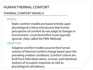
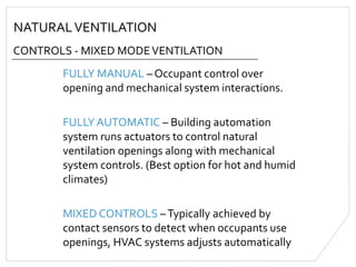
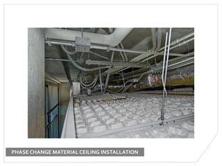
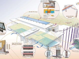
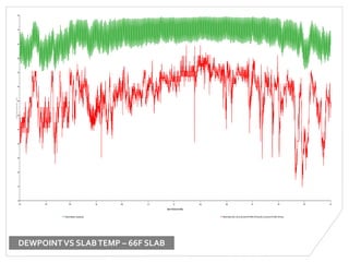
NATURALVENTILATION AND
HYDRONIC COOLING IN
HUMID CLIMATES
GULF COAST GREEN 2013
Matthew Brugman, MSCE, LEED AP BD+C
AIA/CES
“Affiliated Engineers, Inc.” is a Registered Provider with The
American Institute of Architects Continuing Education Systems
(AIA/CES). Credit(s) earned on completion of this program will
be reported to AIA/CES for AIA members. Certificates of
Completion for both AIA members and non-AIA members are
available upon request.
This program is registered with AIA/CES for continuing
professional education. As such, it does not include content that
may be deemed or construed to be an approval or endorsement
by the AIA of any material of construction or any method or
manner of handling, using, distributing, or dealing in any
material or product.
Questions related to specific materials, methods, and services
will be addressed at the conclusion of this presentation.
COURSE DESCRIPTION
This session is intended to review the benefits and design
realities of using natural ventilation and hydronic (water-based)
cooling systems in humid climates, with a special emphasis upon
the Gulf Coast. Issues related to occupant comfort, system
control, design implications, and potential failure mechanisms
will be discussed.
LEARNING OBJECTIVES
At the end of this presentation, participants will be able to:
1. Identify the applicability of hydronic cooling and/or natural
ventilation systems in humid climates
2. Understand the basic thermal comfort and mechanical
design challenges of these systems
3. Have a basic understanding of the control implications for
these systems in humid climates
4. Have a basic understanding of the of architectural design
implications of hydronic cooling and natural ventilation
OUTLINE
HUMID CLIMATES
THERMAL COMFORT
NATURALVENTILATION
BENEFITS
APPLICABILITY & APPROACHES
HYDRONIC SYSTEMS
CONDENSATION
CHILLED BEAMS
RADIANT SYSTEMS
HUMANTHERMAL COMFORT
PHYSICAL FACTORS INTHERMAL COMFORT
METABOLIC RATE
CLOTHING LEVELS
AIRTEMPERATURE
RADIANT SURFACETEMPERATURES
AIR SPEED
RELATIVE HUMIDITY
HUMANTHERMAL COMFORT
THERMAL COMFORT MODELS
STATIC
Static comfort models are based entirely upon
physiological criteria and assume that human
perceptions of comfort do not adapt to changes in
environment. Local discomfort issues typically
ignored. (Also called the PMV Method)
ADAPTIVE
Adaptive comfort models assume that human
notions of thermal comfort change based upon the
prevailing outdoor conditions. Comfort criteria are
built from field observation, surveys, and statistical
analysis of occupant responses as well as
physiological calculations.
HUMANTHERMAL COMFORT
ASHRAE 55
The typical comfort standard adopted throughout
the US, ASHRAE 55-2010 provides for both STATIC
andADAPTIVE comfort criteria in system design.
STATIC comfort criteria ranges in ASRHAE 55 are
expressed as a range of allowable air temperatures
and relative humidity values for given conditions.
ADAPTIVE comfort ranges are expressed in terms of
prevailing mean outdoor air temperature and the
OPERATIVETEMPERATURE.
HUMANTHERMAL COMFORT
ASRHAE 55 – STATIC COMFORT MODEL (PMV)
Air Speed = 30 fpm
Metabolic Rate = 1.2 met (standing)
Clothing = .5 clo (summer indoor clothing)
Air Speed = 30 fpm
Metabolic Rate = 1.7 met (slow walk)
Clothing = .36 clo (shorts & t-shirt)
HUMANTHERMAL COMFORT
ASRHAE 55 – ADAPTIVE COMFORT MODEL
The ASHRAE 55 ADAPTIVE comfort ranges are
generally used when determining the comfort of a
natural ventilation scenario as it assumes that
occupants are free to adapt their clothing and other
conditions.
OPERATIVETEMPERATURE is the combined
temperature that humans actually experience when
the mean radiant temperature and dry bulb air
temperature are accounted for together. At its
simplest, it’s the average of radiant and dry bulb
temperatures in space.
HUMANTHERMAL COMFORT
ASRHAE 55 – ADAPTIVE COMFORT MODEL
Air Speed = 60 fpm Air Speed = 180 fpm
90% acceptability 80% acceptability
HUMANTHERMAL COMFORT
LOCAL DISCOMFORT
There are specific instances when discomfort local to
a small area must be addressed:
RADIANT ASYMMETRY – Large differences between
radiant surface temperatures create asymmetrical
heat loss/gain, a condition which distracts occupants
and can lead to discomfort.
DRAFTS – High air speeds at low temperatures can
create localized excessive cooling.
HUMANTHERMAL COMFORT
LOCAL DISCOMFORT
VERTICALTEMPERATURE DIFFERENCE – A change
of more than 5 to 7 degrees from head to toe is often
uncomfortable. Especially important for stratified
systems such as displacement ventilation and under
floor systems.
FLOOR SURFACETEMPERATURE – Low floor
temperatures can create too much conduction of
heat out of the feet, creating excessive cooling the
extremities. Floor temperatures below 62F should be
avoided, with 65F or higher being preferable.
HUMANTHERMAL COMFORT
WHAT DOES IT ALL MEAN?
If building occupants are allowed to adapt their
clothing to ambient conditions, comfort boils down
to controlling three aspects:
RADIANT SURFACETEMPERATURES
AIRTEMPERATURE
AIR SPEED
VERNACULAR SOLUTIONS
WHAT DIDWE EVER DOWITHOUT A/C??
DEEP SHADESTO CONTROL
SURFACETEMPERATURE
VERNACULAR SOLUTIONS
WHAT DIDWE EVER DOWITHOUT A/C??
CROSS FLOW AND STACKVENTILATION
TO INCREASE AIR SPEED
NATURALVENTILATION
BENEFITS
OCCUPANT CONTROL – Providing individual control
over natural ventilation reduces occupant comfort
complaint
ENERGY SAVINGS –When outside air conditions
allow for natural ventilation, cooling and heating
energy use can be reduced or eliminated
ROBUSTNESS – Buildings with natural ventilation
can continue to function even during mechanical
failures
HEALTH – Natural ventilation provides direct access
to outside air and has been shown to reduce the
spread of infection in healthcare settings
NATURALVENTILATION
APPROACHES – NATURALVENTILATION
STACKVENTILATION – Moving air primarily via
natural convection currents and thermal
buoyancy
WIND DRIVEN – Positioning openings to take
advantage of pressure differentials and wind to
move air through a space
CROSS FLOW vs SINGLE SIDED
UNIVERSITY OF WASHINGTON – HUSKY UNION BUILDING
PLAIN,WI – GREENTTEC
UC RIVERSIDE – SCHOOL OF MEDICINE
KAUST
NATURALVENTILATION
DRAWBACKS – NATURALVENTILATION
MOISTURE – Full natural ventilation systems
offer no means to control moisture and humidity
NOISE & POLLUTION – Negative exterior
conditions are difficult to address with natural
ventilation systems
FINE CONTROL – Natural ventilation provides
only coarse control over pressure and
temperature relationships
NATURALVENTILATION
APPROACHES – MIXED MODEVENTILATION
MIXED MODE – A combination of traditional
mechanical solutions and natural ventilation.
Mechanical systems supplement natural
ventilation processes when thermal comfort
cannot be maintained.
CONCURRENT – Same space, same time
CHANGE-OVER – Same space, different time
ZONED – Different spaces
UNIVERSITY OF WASHINGTON – MOLECULAR ENGINEERING
NATURALVENTILATION
CONTROLS - MIXED MODEVENTILATION
FULLY MANUAL – Occupant control over
opening and mechanical system interactions.
FULLY AUTOMATIC – Building automation
system runs actuators to control natural
ventilation openings along with mechanical
system controls. (Best option for hot and humid
climates)
MIXED CONTROLS –Typically achieved by
contact sensors to detect when occupants use
openings, HVAC systems adjusts automatically
NATURALVENTILATION
DRAWBACKS – MIXED MODEVENTILATION
CONTROLS – Integration of control systems can
be difficult, and training staff in proper system
control is critical
FIRE & SMOKE – Concerns over smoke migration
ENERGY CODES – Many energy codes and
authorities deter the use of operable windows
and mechanical HVAC in the same space
NATURALVENTILATION
APPLICABILITY INTHE GULF COAST
HOUSTON
NEW
ORLEANS
MIAMI FRANKFURT
80%
ADAPTIVE
COMFORT
40% OF
HOURS
9AM-6PM
46% OF
HOURS
9AM-6PM
61% OF
HOURS
9AM-6PM
17% OF
HOURS
9AM-6PM
90%
ADAPTIVE
COMFORT
29% OF
HOURS
9AM-6PM
33% OF
HOURS
9AM-6PM
44% OF
HOURS
9AM-6PM
12% OF
HOURS
9AM-6PM
If we can manage humidity, the Gulf Coast has a very
large potential for natural ventilation systems to be
effective
NATURALVENTILATION
CONTROLLING HUMIDITY
MIXED MODE SYSTEMS – Allow the use of
mechanical system when needed
SCHEDULING – Night flush and pre-cooling can
allow a space to ride through hot periods
AIR SPEED – Increased air speeds counteract the
discomfort of increased humidity levels
CONCURRENT DEHUMIDIFICATION –
Dehumidification through Dedicated Outside Air
Systems (DOAS), in situ dehumidifiers, etc
PHASE CHANGE MATERIAL CEILING INSTALLATION
AIR SPEED IS CRITICAL!
HYDRONIC COOLING
WATERVS AIR
HEATTRANSFER
Water is a much more effective heat transfer
medium than air
VOLUME
The volume of water needed to carry a certain
amount of heat is much smaller than the same
volume of air (1” pipe can carry as much energy as
18” rectangular duct)
PUMPING
Water pumps are mechanically more efficient than
fans, reduced noise
HYDRONIC COOLING
TYPICAL SYSTEMTYPES
RADIANT
Water is used to heat/cool surfaces for radiant heat
transfer (includes chilled sails)
FAN UNITS
Small fan/coil combinations that blow warm/cold air
into a space (includes wall induction units)
CHILLED BEAMS
A special diffuser/coil combination that induces
space air to flow over a coil filled with chilled water.
Can be active or passive.
HYDRONIC COOLING
CHILLED BEAMS - PASSIVE
~ 6 watts of cooling capacity per linear foot
HYDRONIC COOLING
CHILLED BEAMS - ACTIVE
~ 12+ watts of cooling capacity per linear foot
FROM EXPERIMENTALTO MUNDANE
HYDRONIC COOLING
CHILLED BEAM MOISTURE CONTROL
MOISTURE SENSORS
Moisture sensors on the chilled beam coil can reset
the water temperature in the beam
DEW POINT CONTROL
By properly dehumidifying the air supplied to a
chilled beam or space, the dew point can be
suppressed to avoid condensation
*Active chilled beams create a microclimate around
the coil surface and can operate with water several
degrees below the dew point without forming
condensation
HYDRONIC COOLING
DEDICATED OUTSIDE AIR SYSTEMS (DOAS)
DOAS
DOAS systems are intended to condition only
outside ventilation air supplied to a space, and are
typically design to filter and dehumidify air with or
without energy recovery. DOAS systems are often
constant volume, but at very low supply volumes.
Because DOAS systems are not the primary cooling
system, ductwork tends to be much smaller than in a
traditionalVAV system.
HYDRONIC COOLING
TYPICAL RADIANT SYSTEMS
RADIANT SLAB –Tubing is embedded in a floor
or ceiling slab to heat and cool the surface
PANELS – Metal panels are heated or cooled to
create the radiant surface, typically ceiling
mounted
CHILLED SAILS – A radiant cooling panel with
multiple openings meant to provide more
convective cooling
PLAIN,WI – GREENTTEC
STANFORD – CESI ADMIN
Jan Feb Mar Apr May Jun Jul Aug Sep Oct Nov Dec Jan
75
70
65
60
55
50
45
40
35
30
25
20
15
10
Temperature(°F)
Date:Fri01/JantoFri31/Dec
Surfacetemperature: (proposed.aps) External dew-pointtemp.:USA_CA_San.Jose.Intl.AP.724945_TMY3.epw(USA_CA_San.Jose.Intl.AP.724945_TMY3.epw)
DEWPOINTVS SLABTEMP – 66F SLAB
DEWPOINTVS SLABTEMP – 62F SLAB
Jan Feb Mar Apr May Jun Jul Aug Sep Oct Nov Dec Jan
80
70
60
50
40
30
20
10
Temperature(°F)
Date:Fri01/JantoFri31/Dec
External dew-pointtemp.:USA_CA_San.Jose.Intl.AP.724945_TMY3.epw(USA_CA_San.Jose.Intl.AP.724945_TMY3.epw) Surfacetemperature: (proposedat62wosails.aps)
HYDRONIC COOLING
RESPONSETIME
Radiant systems (especially slabs) respond slowly
to changes in thermal load, so good application
of radiant technology will include strategies to
reduce thermal gains:
Orientation
Shading
Sufficient Insulation
Proper Glazing Selection
Pick the low-hanging fruit first!
HYDRONIC COOLING
RESPONSETIME
01 02 03 04 05 06 07 08 09 10 11
88
86
84
82
80
78
76
74
72
70
Temperature(°F)
Date: Thu 01/Jul to Sat 10/Jul
Air temperature: Flex Space (sesi radiant floor.aps)
HYDRONIC COOLING
CAPACITY
MAKINGTHE CASE FOR NATVENT & HYDRONIC
WHAT DOES IT COST?
FIRST COST – First costs can be higher than
traditional HVAC systems, especially mixed mode
natural ventilation
BUILDING REUSE – Because nat vent and
hydronic systems take up less space, older
facilities can be successfully reused
LIFE CYCLE COSTS –Typical NV and radiant
systems have very beneficial life cycle costs, but
not short term (less than 10 year) paybacks
QUESTIONS?
Matthew Brugman
mbrugman@aeieng.com
This concludesThe American Institute of Architects
Continuing Education Systems Course

Natural Ventilation and Hydronic Cooling in Humid Climates

  • 1.
    NATURALVENTILATION AND HYDRONIC COOLINGIN HUMID CLIMATES GULF COAST GREEN 2013 Matthew Brugman, MSCE, LEED AP BD+C
  • 2.
    AIA/CES “Affiliated Engineers, Inc.”is a Registered Provider with The American Institute of Architects Continuing Education Systems (AIA/CES). Credit(s) earned on completion of this program will be reported to AIA/CES for AIA members. Certificates of Completion for both AIA members and non-AIA members are available upon request. This program is registered with AIA/CES for continuing professional education. As such, it does not include content that may be deemed or construed to be an approval or endorsement by the AIA of any material of construction or any method or manner of handling, using, distributing, or dealing in any material or product. Questions related to specific materials, methods, and services will be addressed at the conclusion of this presentation.
  • 3.
    COURSE DESCRIPTION This sessionis intended to review the benefits and design realities of using natural ventilation and hydronic (water-based) cooling systems in humid climates, with a special emphasis upon the Gulf Coast. Issues related to occupant comfort, system control, design implications, and potential failure mechanisms will be discussed.
  • 4.
    LEARNING OBJECTIVES At theend of this presentation, participants will be able to: 1. Identify the applicability of hydronic cooling and/or natural ventilation systems in humid climates 2. Understand the basic thermal comfort and mechanical design challenges of these systems 3. Have a basic understanding of the control implications for these systems in humid climates 4. Have a basic understanding of the of architectural design implications of hydronic cooling and natural ventilation
  • 5.
    OUTLINE HUMID CLIMATES THERMAL COMFORT NATURALVENTILATION BENEFITS APPLICABILITY& APPROACHES HYDRONIC SYSTEMS CONDENSATION CHILLED BEAMS RADIANT SYSTEMS
  • 6.
    HUMANTHERMAL COMFORT PHYSICAL FACTORSINTHERMAL COMFORT METABOLIC RATE CLOTHING LEVELS AIRTEMPERATURE RADIANT SURFACETEMPERATURES AIR SPEED RELATIVE HUMIDITY
  • 7.
  • 8.
    HUMANTHERMAL COMFORT THERMAL COMFORTMODELS STATIC Static comfort models are based entirely upon physiological criteria and assume that human perceptions of comfort do not adapt to changes in environment. Local discomfort issues typically ignored. (Also called the PMV Method) ADAPTIVE Adaptive comfort models assume that human notions of thermal comfort change based upon the prevailing outdoor conditions. Comfort criteria are built from field observation, surveys, and statistical analysis of occupant responses as well as physiological calculations.
  • 9.
    HUMANTHERMAL COMFORT ASHRAE 55 Thetypical comfort standard adopted throughout the US, ASHRAE 55-2010 provides for both STATIC andADAPTIVE comfort criteria in system design. STATIC comfort criteria ranges in ASRHAE 55 are expressed as a range of allowable air temperatures and relative humidity values for given conditions. ADAPTIVE comfort ranges are expressed in terms of prevailing mean outdoor air temperature and the OPERATIVETEMPERATURE.
  • 11.
    HUMANTHERMAL COMFORT ASRHAE 55– STATIC COMFORT MODEL (PMV) Air Speed = 30 fpm Metabolic Rate = 1.2 met (standing) Clothing = .5 clo (summer indoor clothing) Air Speed = 30 fpm Metabolic Rate = 1.7 met (slow walk) Clothing = .36 clo (shorts & t-shirt)
  • 12.
    HUMANTHERMAL COMFORT ASRHAE 55– ADAPTIVE COMFORT MODEL The ASHRAE 55 ADAPTIVE comfort ranges are generally used when determining the comfort of a natural ventilation scenario as it assumes that occupants are free to adapt their clothing and other conditions. OPERATIVETEMPERATURE is the combined temperature that humans actually experience when the mean radiant temperature and dry bulb air temperature are accounted for together. At its simplest, it’s the average of radiant and dry bulb temperatures in space.
  • 13.
    HUMANTHERMAL COMFORT ASRHAE 55– ADAPTIVE COMFORT MODEL Air Speed = 60 fpm Air Speed = 180 fpm 90% acceptability 80% acceptability
  • 14.
    HUMANTHERMAL COMFORT LOCAL DISCOMFORT Thereare specific instances when discomfort local to a small area must be addressed: RADIANT ASYMMETRY – Large differences between radiant surface temperatures create asymmetrical heat loss/gain, a condition which distracts occupants and can lead to discomfort. DRAFTS – High air speeds at low temperatures can create localized excessive cooling.
  • 15.
    HUMANTHERMAL COMFORT LOCAL DISCOMFORT VERTICALTEMPERATUREDIFFERENCE – A change of more than 5 to 7 degrees from head to toe is often uncomfortable. Especially important for stratified systems such as displacement ventilation and under floor systems. FLOOR SURFACETEMPERATURE – Low floor temperatures can create too much conduction of heat out of the feet, creating excessive cooling the extremities. Floor temperatures below 62F should be avoided, with 65F or higher being preferable.
  • 16.
    HUMANTHERMAL COMFORT WHAT DOESIT ALL MEAN? If building occupants are allowed to adapt their clothing to ambient conditions, comfort boils down to controlling three aspects: RADIANT SURFACETEMPERATURES AIRTEMPERATURE AIR SPEED
  • 17.
    VERNACULAR SOLUTIONS WHAT DIDWEEVER DOWITHOUT A/C?? DEEP SHADESTO CONTROL SURFACETEMPERATURE
  • 18.
    VERNACULAR SOLUTIONS WHAT DIDWEEVER DOWITHOUT A/C?? CROSS FLOW AND STACKVENTILATION TO INCREASE AIR SPEED
  • 19.
    NATURALVENTILATION BENEFITS OCCUPANT CONTROL –Providing individual control over natural ventilation reduces occupant comfort complaint ENERGY SAVINGS –When outside air conditions allow for natural ventilation, cooling and heating energy use can be reduced or eliminated ROBUSTNESS – Buildings with natural ventilation can continue to function even during mechanical failures HEALTH – Natural ventilation provides direct access to outside air and has been shown to reduce the spread of infection in healthcare settings
  • 20.
    NATURALVENTILATION APPROACHES – NATURALVENTILATION STACKVENTILATION– Moving air primarily via natural convection currents and thermal buoyancy WIND DRIVEN – Positioning openings to take advantage of pressure differentials and wind to move air through a space CROSS FLOW vs SINGLE SIDED
  • 21.
    UNIVERSITY OF WASHINGTON– HUSKY UNION BUILDING
  • 25.
  • 28.
    UC RIVERSIDE –SCHOOL OF MEDICINE
  • 32.
  • 34.
    NATURALVENTILATION DRAWBACKS – NATURALVENTILATION MOISTURE– Full natural ventilation systems offer no means to control moisture and humidity NOISE & POLLUTION – Negative exterior conditions are difficult to address with natural ventilation systems FINE CONTROL – Natural ventilation provides only coarse control over pressure and temperature relationships
  • 35.
    NATURALVENTILATION APPROACHES – MIXEDMODEVENTILATION MIXED MODE – A combination of traditional mechanical solutions and natural ventilation. Mechanical systems supplement natural ventilation processes when thermal comfort cannot be maintained. CONCURRENT – Same space, same time CHANGE-OVER – Same space, different time ZONED – Different spaces
  • 37.
    UNIVERSITY OF WASHINGTON– MOLECULAR ENGINEERING
  • 40.
    NATURALVENTILATION CONTROLS - MIXEDMODEVENTILATION FULLY MANUAL – Occupant control over opening and mechanical system interactions. FULLY AUTOMATIC – Building automation system runs actuators to control natural ventilation openings along with mechanical system controls. (Best option for hot and humid climates) MIXED CONTROLS –Typically achieved by contact sensors to detect when occupants use openings, HVAC systems adjusts automatically
  • 41.
    NATURALVENTILATION DRAWBACKS – MIXEDMODEVENTILATION CONTROLS – Integration of control systems can be difficult, and training staff in proper system control is critical FIRE & SMOKE – Concerns over smoke migration ENERGY CODES – Many energy codes and authorities deter the use of operable windows and mechanical HVAC in the same space
  • 42.
    NATURALVENTILATION APPLICABILITY INTHE GULFCOAST HOUSTON NEW ORLEANS MIAMI FRANKFURT 80% ADAPTIVE COMFORT 40% OF HOURS 9AM-6PM 46% OF HOURS 9AM-6PM 61% OF HOURS 9AM-6PM 17% OF HOURS 9AM-6PM 90% ADAPTIVE COMFORT 29% OF HOURS 9AM-6PM 33% OF HOURS 9AM-6PM 44% OF HOURS 9AM-6PM 12% OF HOURS 9AM-6PM If we can manage humidity, the Gulf Coast has a very large potential for natural ventilation systems to be effective
  • 43.
    NATURALVENTILATION CONTROLLING HUMIDITY MIXED MODESYSTEMS – Allow the use of mechanical system when needed SCHEDULING – Night flush and pre-cooling can allow a space to ride through hot periods AIR SPEED – Increased air speeds counteract the discomfort of increased humidity levels CONCURRENT DEHUMIDIFICATION – Dehumidification through Dedicated Outside Air Systems (DOAS), in situ dehumidifiers, etc
  • 46.
    PHASE CHANGE MATERIALCEILING INSTALLATION
  • 48.
    AIR SPEED ISCRITICAL!
  • 51.
    HYDRONIC COOLING WATERVS AIR HEATTRANSFER Wateris a much more effective heat transfer medium than air VOLUME The volume of water needed to carry a certain amount of heat is much smaller than the same volume of air (1” pipe can carry as much energy as 18” rectangular duct) PUMPING Water pumps are mechanically more efficient than fans, reduced noise
  • 52.
    HYDRONIC COOLING TYPICAL SYSTEMTYPES RADIANT Wateris used to heat/cool surfaces for radiant heat transfer (includes chilled sails) FAN UNITS Small fan/coil combinations that blow warm/cold air into a space (includes wall induction units) CHILLED BEAMS A special diffuser/coil combination that induces space air to flow over a coil filled with chilled water. Can be active or passive.
  • 53.
    HYDRONIC COOLING CHILLED BEAMS- PASSIVE ~ 6 watts of cooling capacity per linear foot
  • 54.
    HYDRONIC COOLING CHILLED BEAMS- ACTIVE ~ 12+ watts of cooling capacity per linear foot
  • 56.
  • 57.
    HYDRONIC COOLING CHILLED BEAMMOISTURE CONTROL MOISTURE SENSORS Moisture sensors on the chilled beam coil can reset the water temperature in the beam DEW POINT CONTROL By properly dehumidifying the air supplied to a chilled beam or space, the dew point can be suppressed to avoid condensation *Active chilled beams create a microclimate around the coil surface and can operate with water several degrees below the dew point without forming condensation
  • 59.
    HYDRONIC COOLING DEDICATED OUTSIDEAIR SYSTEMS (DOAS) DOAS DOAS systems are intended to condition only outside ventilation air supplied to a space, and are typically design to filter and dehumidify air with or without energy recovery. DOAS systems are often constant volume, but at very low supply volumes. Because DOAS systems are not the primary cooling system, ductwork tends to be much smaller than in a traditionalVAV system.
  • 64.
    HYDRONIC COOLING TYPICAL RADIANTSYSTEMS RADIANT SLAB –Tubing is embedded in a floor or ceiling slab to heat and cool the surface PANELS – Metal panels are heated or cooled to create the radiant surface, typically ceiling mounted CHILLED SAILS – A radiant cooling panel with multiple openings meant to provide more convective cooling
  • 65.
  • 70.
  • 73.
    Jan Feb MarApr May Jun Jul Aug Sep Oct Nov Dec Jan 75 70 65 60 55 50 45 40 35 30 25 20 15 10 Temperature(°F) Date:Fri01/JantoFri31/Dec Surfacetemperature: (proposed.aps) External dew-pointtemp.:USA_CA_San.Jose.Intl.AP.724945_TMY3.epw(USA_CA_San.Jose.Intl.AP.724945_TMY3.epw) DEWPOINTVS SLABTEMP – 66F SLAB
  • 74.
    DEWPOINTVS SLABTEMP –62F SLAB Jan Feb Mar Apr May Jun Jul Aug Sep Oct Nov Dec Jan 80 70 60 50 40 30 20 10 Temperature(°F) Date:Fri01/JantoFri31/Dec External dew-pointtemp.:USA_CA_San.Jose.Intl.AP.724945_TMY3.epw(USA_CA_San.Jose.Intl.AP.724945_TMY3.epw) Surfacetemperature: (proposedat62wosails.aps)
  • 76.
    HYDRONIC COOLING RESPONSETIME Radiant systems(especially slabs) respond slowly to changes in thermal load, so good application of radiant technology will include strategies to reduce thermal gains: Orientation Shading Sufficient Insulation Proper Glazing Selection Pick the low-hanging fruit first!
  • 77.
    HYDRONIC COOLING RESPONSETIME 01 0203 04 05 06 07 08 09 10 11 88 86 84 82 80 78 76 74 72 70 Temperature(°F) Date: Thu 01/Jul to Sat 10/Jul Air temperature: Flex Space (sesi radiant floor.aps)
  • 78.
  • 79.
    MAKINGTHE CASE FORNATVENT & HYDRONIC WHAT DOES IT COST? FIRST COST – First costs can be higher than traditional HVAC systems, especially mixed mode natural ventilation BUILDING REUSE – Because nat vent and hydronic systems take up less space, older facilities can be successfully reused LIFE CYCLE COSTS –Typical NV and radiant systems have very beneficial life cycle costs, but not short term (less than 10 year) paybacks
  • 80.
    QUESTIONS? Matthew Brugman mbrugman@aeieng.com This concludesTheAmerican Institute of Architects Continuing Education Systems Course