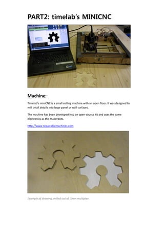
This document provides information on the machines used in the workshop on open‐
    source 3D‐printers and milling machines, at the Howest Summerschool on the 31st of 
    August. 
     
    If you prepare a small 3D‐object and/or a 2D‐profile to be cut, you will have the 
    opportunity to print/mill this yourself during the workshop. This document outlines 
    the parameters of the files to be prepared. It also provides links to the software you’ll 
    need. Installing this ahead of time will allow us to get started faster during the 
    workshop. Please do so. 

    If parts of this explanation are unclear, or you’ve got stuck while installing the 
    software, you can contact: lieven.standaert@timelab.org 


    PART1: MAKERBOT 3D-PRINTER


    Machine:
    The makerbot is an open‐source design for a 3D‐printer. This means the build plans 
    are distributed on‐line and all users can modify or (try to) improve their machines. 
    Over 5000 of these machines have been built and because of this open‐source design 
    strategy they are evolving very fast.  

    The machine creates small objects in plastic (ABS or PLA). This is done by melting the 
    plastic in a hot print head, then extruding a thin filament of this plastic. The machine 
    then draws with the plastic and builds the 3D‐object layer by layer. 
    http://www.makerbot.com 


Examples of objects made on the Makerbot 


Process:
1‐An STL‐file is imported into the control software, REPLICATORG. .STL is a 3D‐file 
format. Most 3D‐software is capable of exporting in this format. Objects need to be 
‘watertight’: they need to have an inside and outside. 
 
3D‐model in replicatorG 

 2‐ When this is done, the 3D‐object is cut into layers. Each layer is a 2D drawing. This 
is converted into a description that can be sent to the 3D‐printer. 
This is complicated to achieve, but there’s a preconfigured piece of software to do 
this for you. It is called SKEINFORGE, and is integrated into ReplicatorG. 

Skeinforge has a lot of customizable settings, allowing you to define things like layer 
thickness, solidity of your object, print speed and temperature. 
As a novice user you can use preconfigured setting, but sooner or later you will need 
to dig into this. 


GCODE of the object in the previous image 


3‐The output of Skeinforge is a text‐file with machine code. This code is called 
GCODE, en is in essence a long list of X,Y, Z‐coordinates to be sent to the printer. 
4‐In ReplicatorG there is a CONTROL PANEL. This controls the printer directly. You 
    use it to position the print head and to heat up the printer.  

    5‐Once this is done, you send the Gcode to the printer, and build the object 


    Limitations:
    ‐like most 3D‐printers, this technology is limited to small volumes. Big objects take 
    long to print. 

    ‐these machines do not print a support material, unlike most commercial machines. 
    This means you can’t lay down plastic in mid‐air. The little whistle in the image above 
    is printed on its side, you can’t print it the right way up. Overhangs of more than 45° 
    are not possible.  


    File description:
    Format:  STL‐file* 
    Maximum dimensions: 5x5x5cm** 
    Maximum overhang: 45° 
    Minimum wall thickness for hollow objects:1mm 

     *Autocad, 3Dsmax, Sketchup and most other 3D‐software can export this. 

    **de Makerbots can print up to 10x10x12h, but within the context of this workshop 
    this would take too long. 
    Alternatively, your object could consist of multiple smaller objects, spread out over a 
    10x10 build surface. 


    Preparation:
    1‐Download en unzip Replicatorg: http://www.replicat.org 

    2‐EITHER: prepare your own 3D‐model to be printed, within the constraints 
    described in ‘File Description’ above. 

    OR: Go online and take a look on http://www.thingiverse.com You can find a lot of 
    objects there that can be printed. Choose something that is not too large and that 
    has actually been printed by more than one person. Save the file and bring it to the 
    workshop. 
PART2: timelab’s MINICNC


Machine:
Timelab’s miniCNC is a small milling machine with an open floor. It was designed to 
mill small details into large panel or wall surfaces. 

The machine has been developed into an open‐source kit and uses the same 
electronics as the Makerbots. 

http://www.repairablemachines.com 


Example of drawing, milled out of  5mm multiplex 
Process:
    The software does not use a 3D‐model, though the machine can do 3D‐objects. For 
    ease of use, the software uses a black & white or grayscale bitmap. In a Python‐script 
    the Gcode for the machine is generated from this 2D‐drawing. 


    The orange lines in the image above are the generated tool paths. These are saved as 
    Gcode and then opened in ReplicatorG. ReplicatorG controls the machine in the 
    same way as it does the Makerbots. 


    Limitations:
    ‐de Dremel can only be moved straight down. You can mill the top half of a sphere, 
    but not the bottom half. (though we will focus on 2D for this workshop) 

     ‐the machine can move the Dremel 5cm up‐and‐down. In practice you will be limited 
    by the length of your milling bit. You can find a 3mm‐wide milling bit that is 5cm long, 
    but there is no such thing as a 1mm milling bit of 5cm length. 

    ‐when milling a square hole into a surface, the inner corners will bee rounded off by 
    the radius of the milling bit used. 

    ‐the machine does not have a cooling system on the milling bit. You can try milling 
    aluminium, but you will have to take care not to overheat the milling bit. 


File Description:
    Format: PNG‐file, 200 dpi, black&white* 
    Maximum dimensions: 18x18cm 
    Minimum detail: 1mm ** 

    *Everything in black will be milled away. The black areas of the design should not 
    touch the borders of the image. 
    **This is the diameter of the smallest milling bit available 


    Preparation:
    1‐Install the software: an overview of the software to be installed can be found on 
    http://www.repairablemachines.com/downloads.html 

    a‐You will need ReplicatorG. This should be installed already if you prepared for the 
    Makerbot.  
    b‐You need a driver for the machine. This is an XML‐file that needs to be copied into 
    the ReplicatorG install‐directory.  See website for details. 
    c‐ You need to be able to run Python. This is a programming language you can 
    download and install. This is the tricky bit, as you also need to install a number of 
    libraries. The instructions can be found on the webpage, but differ from platform to 
    platform. If you  are unsuccessful installing these, mail  lieven.standaert@timelab.org 
    for assistance. 

    d‐ You can test if everything got installed correctly by trying to run the Python‐script 
    at the bottom of the download‐page. It should run and look similar tot the image 
    above of the software (the image with the ‘A’ under ‘Process’) 

    2‐OPTIONAL: Prepare a PNG‐file, within the parameters described above, of a design 
    you wish to cut out of plate material. Materials like wood, plywood and plexi will be 
    available at Protospace. 

    Best of luck & see you all on the 31st, 
    Lieven 


Briefing makerbot and mini cnc

  • 1.
      This document provides information on the machines used in the workshop on open‐ source 3D‐printers and milling machines, at the Howest Summerschool on the 31st of  August.    If you prepare a small 3D‐object and/or a 2D‐profile to be cut, you will have the  opportunity to print/mill this yourself during the workshop. This document outlines  the parameters of the files to be prepared. It also provides links to the software you’ll  need. Installing this ahead of time will allow us to get started faster during the  workshop. Please do so.  If parts of this explanation are unclear, or you’ve got stuck while installing the  software, you can contact: lieven.standaert@timelab.org    PART1: MAKERBOT 3D-PRINTER Machine: The makerbot is an open‐source design for a 3D‐printer. This means the build plans  are distributed on‐line and all users can modify or (try to) improve their machines.  Over 5000 of these machines have been built and because of this open‐source design  strategy they are evolving very fast.   The machine creates small objects in plastic (ABS or PLA). This is done by melting the  plastic in a hot print head, then extruding a thin filament of this plastic. The machine  then draws with the plastic and builds the 3D‐object layer by layer.  http://www.makerbot.com 
  • 2.
          Examples of objects made on the Makerbot    Process: 1‐An STL‐file is imported into the control software, REPLICATORG. .STL is a 3D‐file  format. Most 3D‐software is capable of exporting in this format. Objects need to be  ‘watertight’: they need to have an inside and outside. 
  • 3.
      3D‐model in replicatorG   2‐ When this is done, the 3D‐object is cut into layers. Each layer is a 2D drawing. This  is converted into a description that can be sent to the 3D‐printer.  This is complicated to achieve, but there’s a preconfigured piece of software to do  this for you. It is called SKEINFORGE, and is integrated into ReplicatorG.  Skeinforge has a lot of customizable settings, allowing you to define things like layer  thickness, solidity of your object, print speed and temperature.  As a novice user you can use preconfigured setting, but sooner or later you will need  to dig into this.      GCODE of the object in the previous image    3‐The output of Skeinforge is a text‐file with machine code. This code is called  GCODE, en is in essence a long list of X,Y, Z‐coordinates to be sent to the printer. 
  • 4.
    4‐In ReplicatorG there is a CONTROL PANEL. This controls the printer directly. You  use it to position the print head and to heat up the printer.   5‐Once this is done, you send the Gcode to the printer, and build the object    Limitations: ‐like most 3D‐printers, this technology is limited to small volumes. Big objects take  long to print.  ‐these machines do not print a support material, unlike most commercial machines.  This means you can’t lay down plastic in mid‐air. The little whistle in the image above  is printed on its side, you can’t print it the right way up. Overhangs of more than 45°  are not possible.     File description: Format:  STL‐file*  Maximum dimensions: 5x5x5cm**  Maximum overhang: 45°  Minimum wall thickness for hollow objects:1mm   *Autocad, 3Dsmax, Sketchup and most other 3D‐software can export this.  **de Makerbots can print up to 10x10x12h, but within the context of this workshop  this would take too long.  Alternatively, your object could consist of multiple smaller objects, spread out over a  10x10 build surface.    Preparation: 1‐Download en unzip Replicatorg: http://www.replicat.org  2‐EITHER: prepare your own 3D‐model to be printed, within the constraints  described in ‘File Description’ above.  OR: Go online and take a look on http://www.thingiverse.com You can find a lot of  objects there that can be printed. Choose something that is not too large and that  has actually been printed by more than one person. Save the file and bring it to the  workshop. 
  • 5.
    PART2: timelab’s MINICNC   Machine: Timelab’s miniCNC is a small milling machine with an open floor. It was designed to  mill small details into large panel or wall surfaces.  The machine has been developed into an open‐source kit and uses the same  electronics as the Makerbots.  http://www.repairablemachines.com    Example of drawing, milled out of  5mm multiplex 
  • 6.
    Process: The software does not use a 3D‐model, though the machine can do 3D‐objects. For  ease of use, the software uses a black & white or grayscale bitmap. In a Python‐script  the Gcode for the machine is generated from this 2D‐drawing.    The orange lines in the image above are the generated tool paths. These are saved as  Gcode and then opened in ReplicatorG. ReplicatorG controls the machine in the  same way as it does the Makerbots.  Limitations: ‐de Dremel can only be moved straight down. You can mill the top half of a sphere,  but not the bottom half. (though we will focus on 2D for this workshop)   ‐the machine can move the Dremel 5cm up‐and‐down. In practice you will be limited  by the length of your milling bit. You can find a 3mm‐wide milling bit that is 5cm long,  but there is no such thing as a 1mm milling bit of 5cm length.  ‐when milling a square hole into a surface, the inner corners will bee rounded off by  the radius of the milling bit used.  ‐the machine does not have a cooling system on the milling bit. You can try milling  aluminium, but you will have to take care not to overheat the milling bit.     
  • 7.
    File Description: Format: PNG‐file, 200 dpi, black&white*  Maximum dimensions: 18x18cm  Minimum detail: 1mm **  *Everything in black will be milled away. The black areas of the design should not  touch the borders of the image.  **This is the diameter of the smallest milling bit available    Preparation: 1‐Install the software: an overview of the software to be installed can be found on  http://www.repairablemachines.com/downloads.html  a‐You will need ReplicatorG. This should be installed already if you prepared for the  Makerbot.   b‐You need a driver for the machine. This is an XML‐file that needs to be copied into  the ReplicatorG install‐directory.  See website for details.  c‐ You need to be able to run Python. This is a programming language you can  download and install. This is the tricky bit, as you also need to install a number of  libraries. The instructions can be found on the webpage, but differ from platform to  platform. If you  are unsuccessful installing these, mail  lieven.standaert@timelab.org  for assistance.  d‐ You can test if everything got installed correctly by trying to run the Python‐script  at the bottom of the download‐page. It should run and look similar tot the image  above of the software (the image with the ‘A’ under ‘Process’)  2‐OPTIONAL: Prepare a PNG‐file, within the parameters described above, of a design  you wish to cut out of plate material. Materials like wood, plywood and plexi will be  available at Protospace.  Best of luck & see you all on the 31st,  Lieven