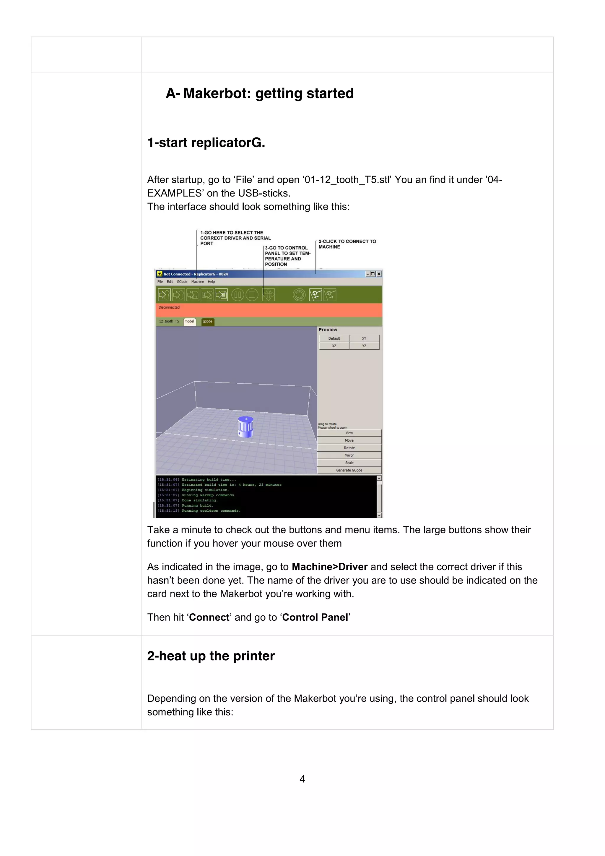
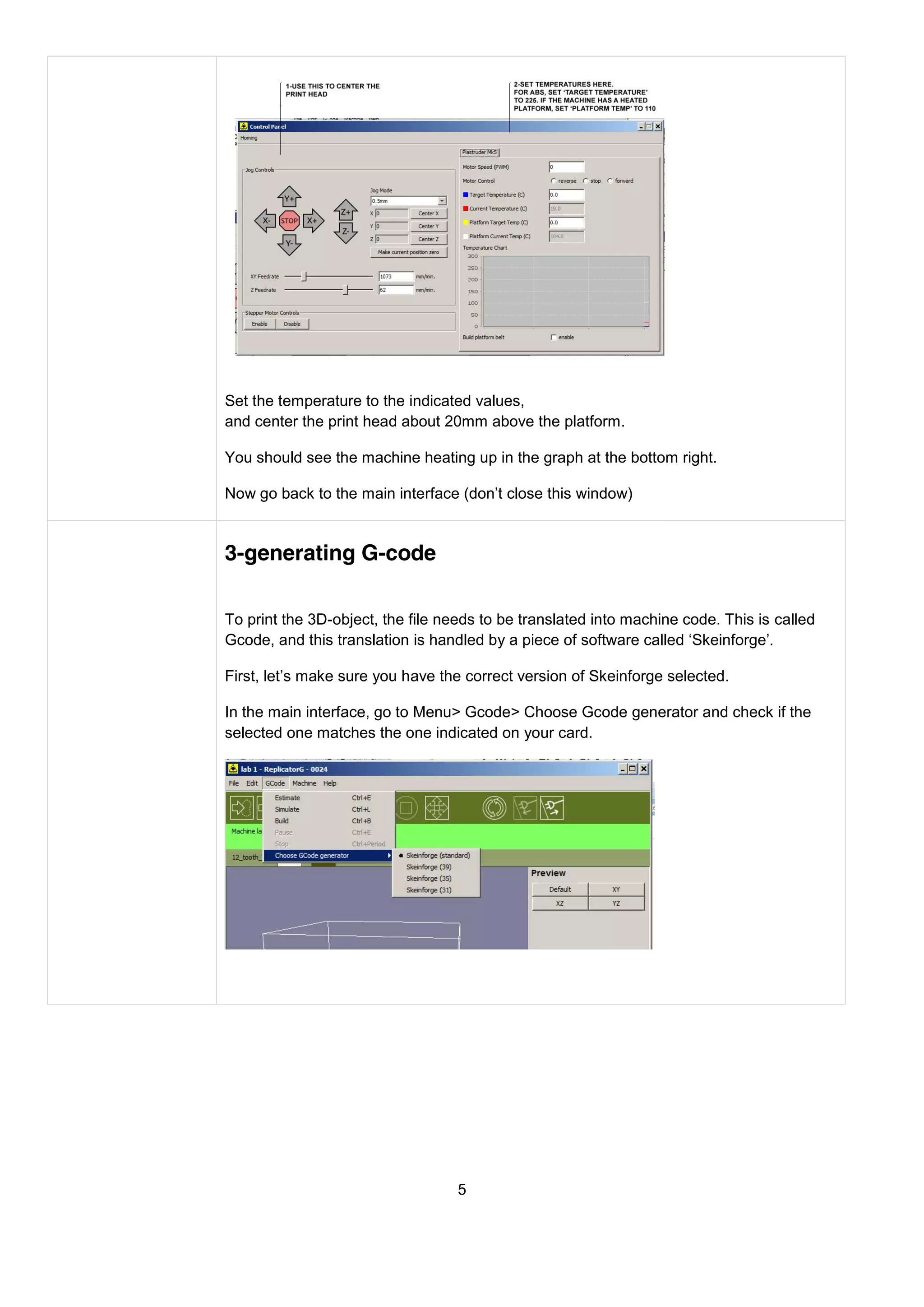
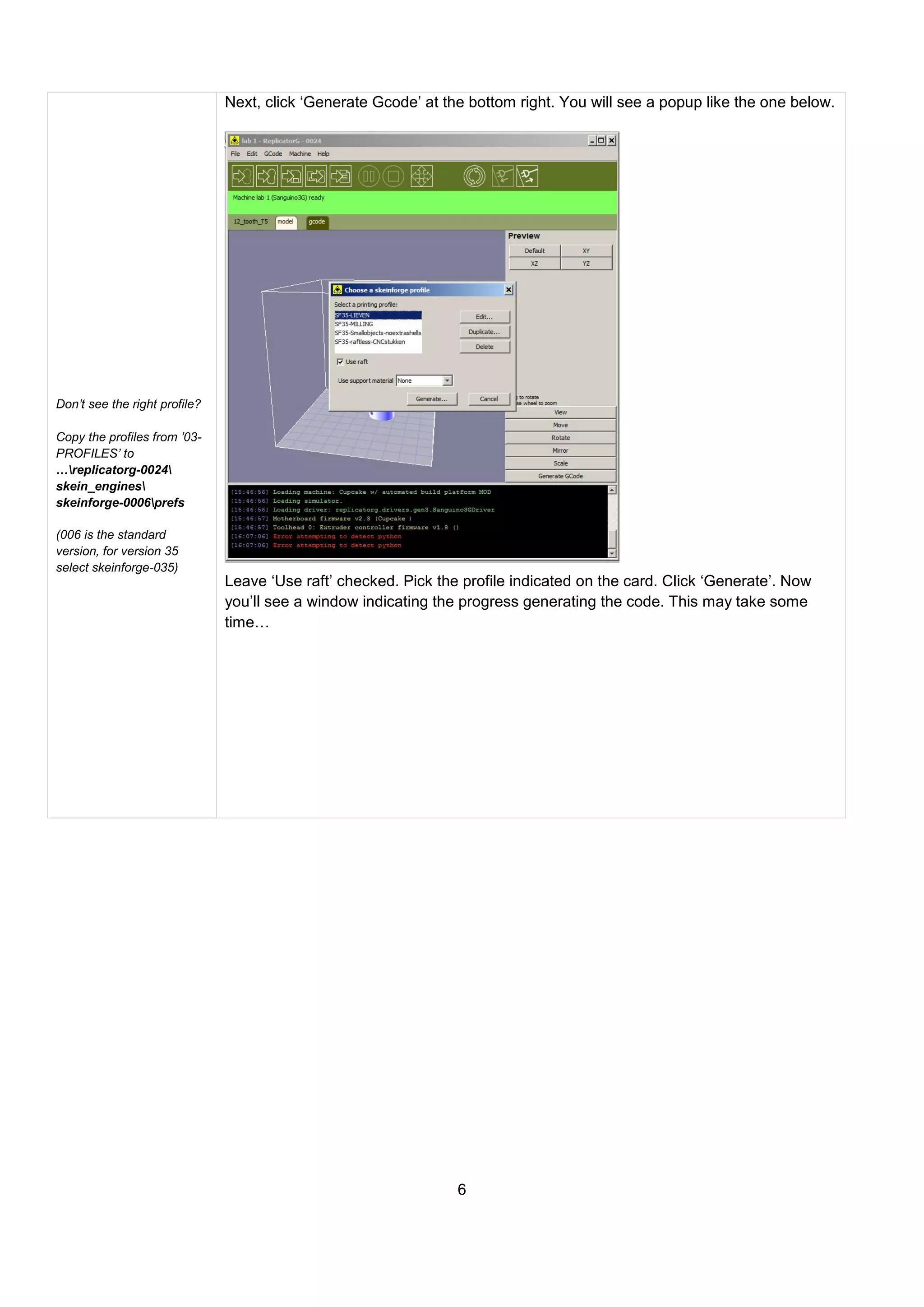
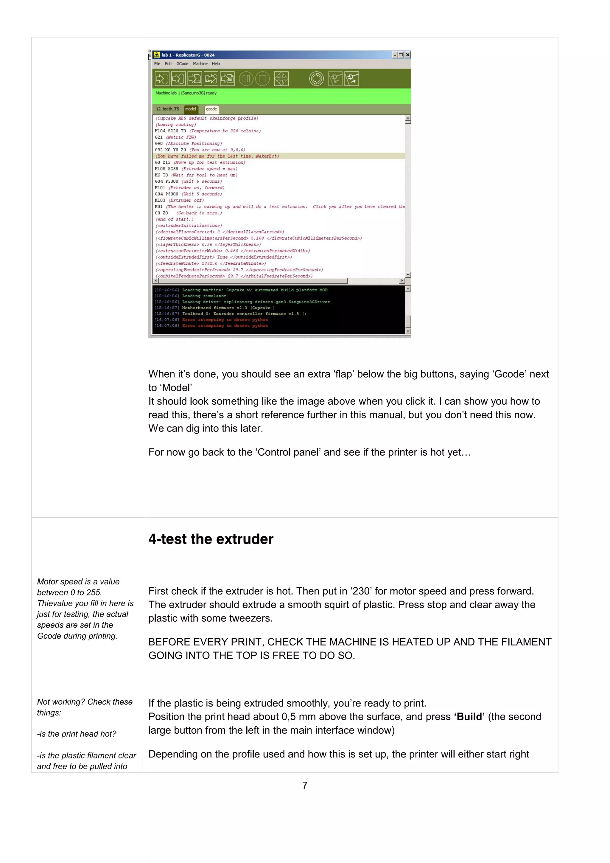
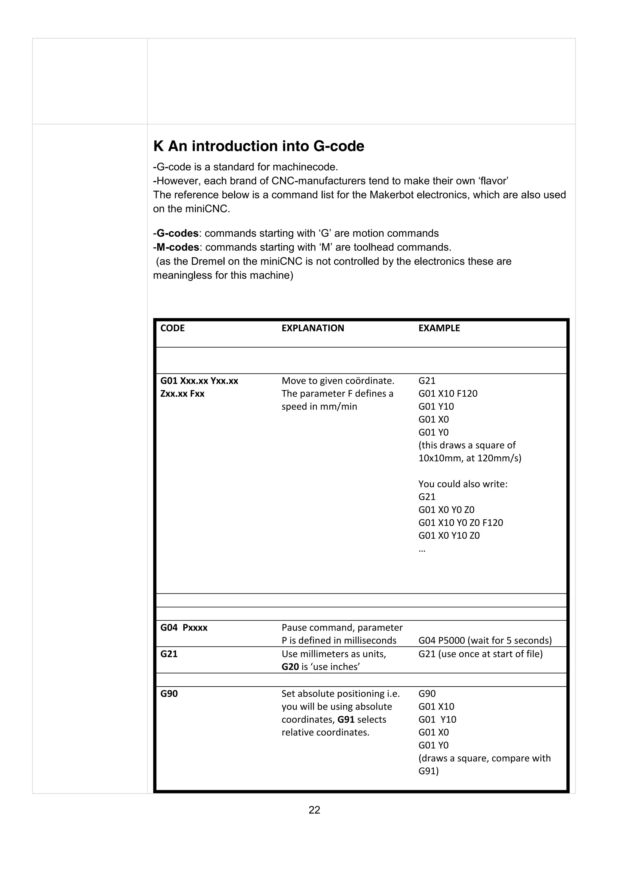
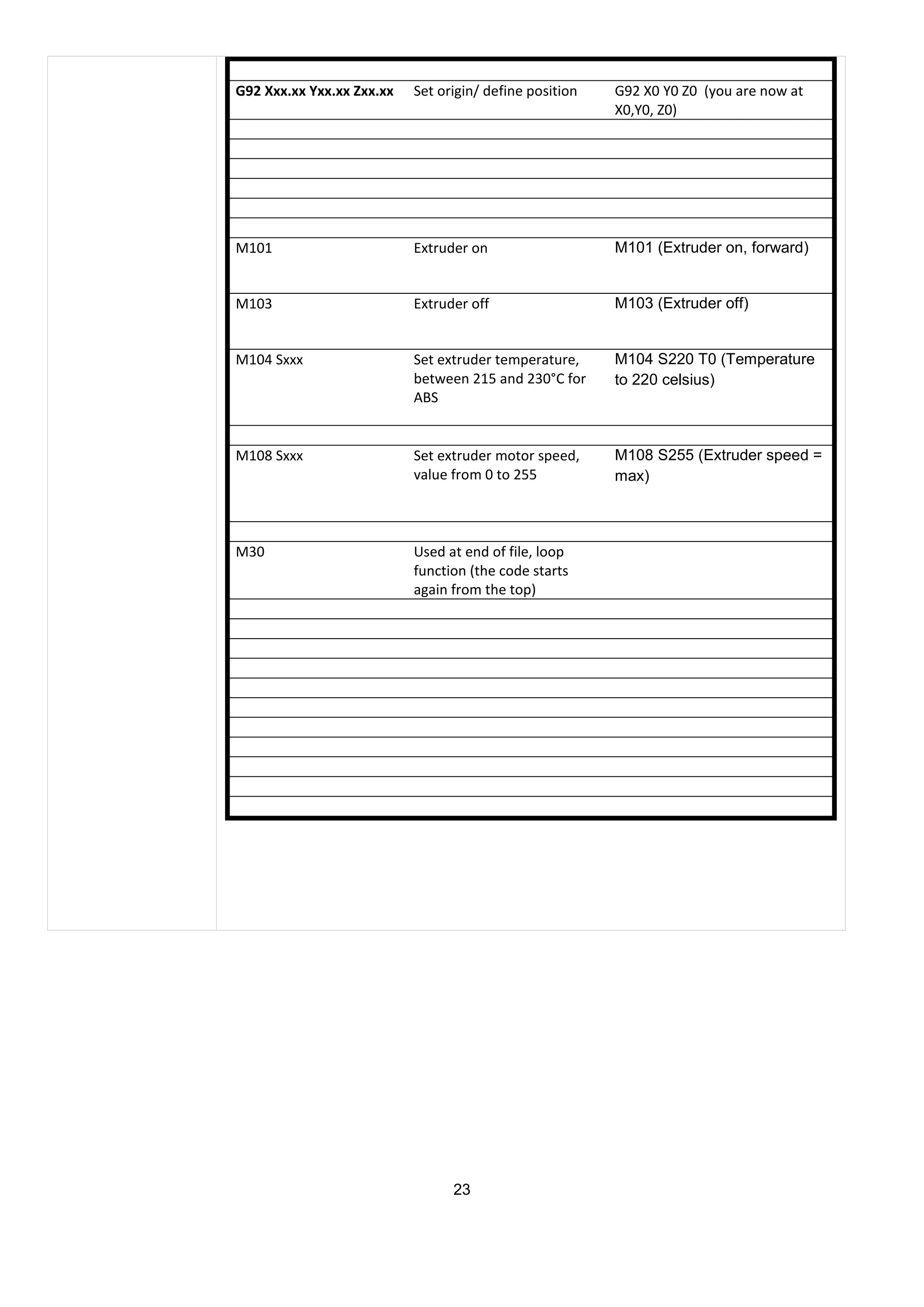
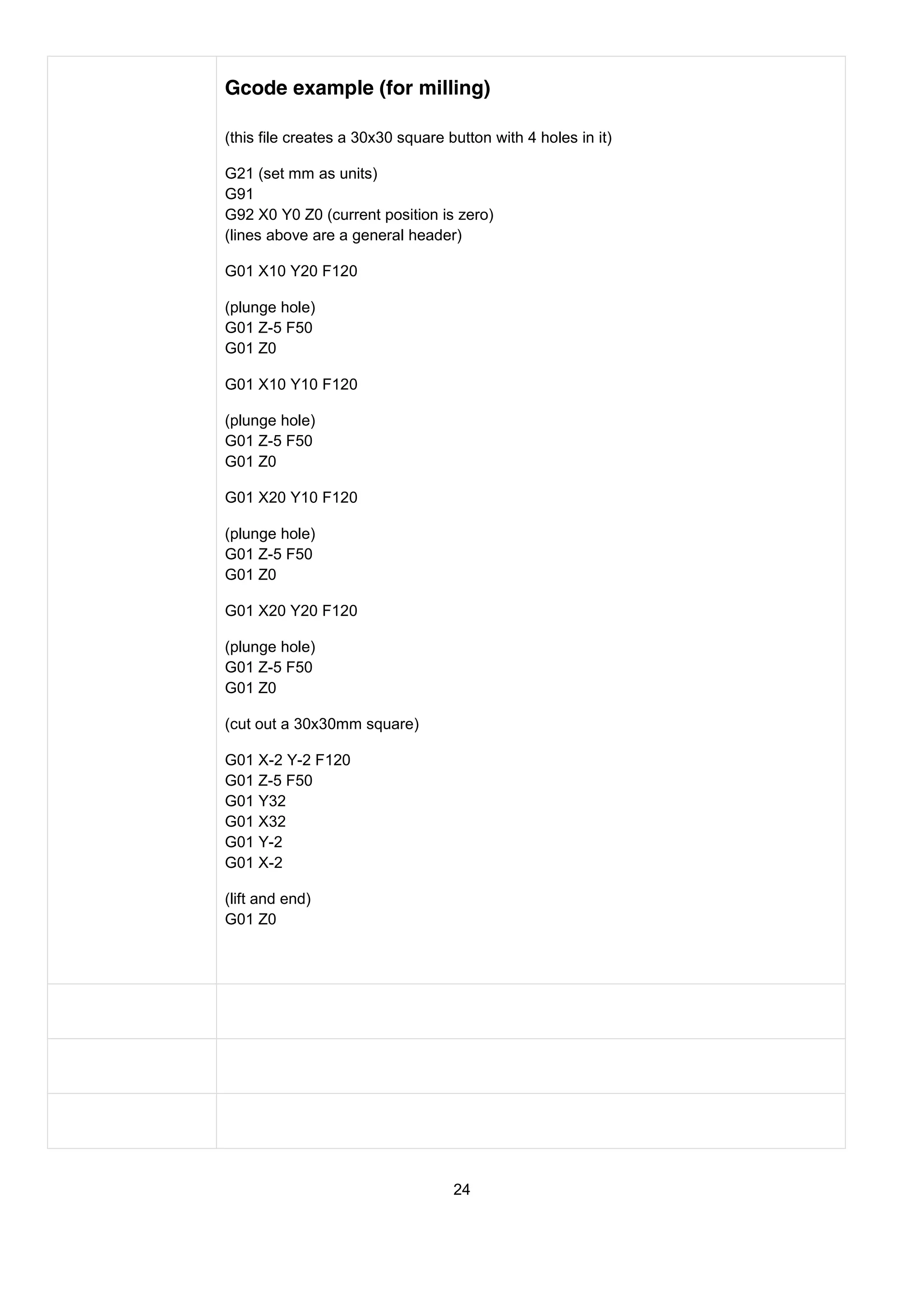
This document provides an overview and instructions for setting up and using a Makerbot 3D printer and CNC milling machine. It covers starting ReplicatorG software, heating up and calibrating the 3D printer extruder, generating G-code from a 3D model, and basic concepts of CNC milling software and G-code. The goal is to demonstrate the basic workflow and get users printing their first 3D object or milling a simple part.
Talk about two projects, in their Astute project he will explain how interfaces can facilitate complex problems in all kinds of domains. In theirSmarcos project the interusability of devices is being investigated.
Neuro-symbolic is not enough, we need neuro-*semantic*Frank van Harmelen
Neuro-symbolic (NeSy) AI is on the rise. However, simply machine learning on just any symbolic structure is not sufficient to really harvest the gains of NeSy. These will only be gained when the symbolic structures have an actual semantics. I give an operational definition of semantics as “predictable inference”.
All of this illustrated with link prediction over knowledge graphs, but the argument is general.
Accelerate your Kubernetes clusters with Varnish CachingThijs Feryn
A presentation about the usage and availability of Varnish on Kubernetes. This talk explores the capabilities of Varnish caching and shows how to use the Varnish Helm chart to deploy it to Kubernetes.
This presentation was delivered at K8SUG Singapore. See https://feryn.eu/presentations/accelerate-your-kubernetes-clusters-with-varnish-caching-k8sug-singapore-28-2024 for more details.
Slack (or Teams) Automation for Bonterra Impact Management (fka Social Soluti...Jeffrey Haguewood
Sidekick Solutions uses Bonterra Impact Management (fka Social Solutions Apricot) and automation solutions to integrate data for business workflows.
We believe integration and automation are essential to user experience and the promise of efficient work through technology. Automation is the critical ingredient to realizing that full vision. We develop integration products and services for Bonterra Case Management software to support the deployment of automations for a variety of use cases.
This video focuses on the notifications, alerts, and approval requests using Slack for Bonterra Impact Management. The solutions covered in this webinar can also be deployed for Microsoft Teams.
Interested in deploying notification automations for Bonterra Impact Management? Contact us at sales@sidekicksolutionsllc.com to discuss next steps.
Generating a custom Ruby SDK for your web service or Rails API using Smithyg2nightmarescribd
Have you ever wanted a Ruby client API to communicate with your web service? Smithy is a protocol-agnostic language for defining services and SDKs. Smithy Ruby is an implementation of Smithy that generates a Ruby SDK using a Smithy model. In this talk, we will explore Smithy and Smithy Ruby to learn how to generate custom feature-rich SDKs that can communicate with any web service, such as a Rails JSON API.
The Art of the Pitch: WordPress Relationships and SalesLaura Byrne
Clients don’t know what they don’t know. What web solutions are right for them? How does WordPress come into the picture? How do you make sure you understand scope and timeline? What do you do if sometime changes?
All these questions and more will be explored as we talk about matching clients’ needs with what your agency offers without pulling teeth or pulling your hair out. Practical tips, and strategies for successful relationship building that leads to closing the deal.
Epistemic Interaction - tuning interfaces to provide information for AI supportAlan Dix
Paper presented at SYNERGY workshop at AVI 2024, Genoa, Italy. 3rd June 2024
https://alandix.com/academic/papers/synergy2024-epistemic/
As machine learning integrates deeper into human-computer interactions, the concept of epistemic interaction emerges, aiming to refine these interactions to enhance system adaptability. This approach encourages minor, intentional adjustments in user behaviour to enrich the data available for system learning. This paper introduces epistemic interaction within the context of human-system communication, illustrating how deliberate interaction design can improve system understanding and adaptation. Through concrete examples, we demonstrate the potential of epistemic interaction to significantly advance human-computer interaction by leveraging intuitive human communication strategies to inform system design and functionality, offering a novel pathway for enriching user-system engagements.
Transcript: Selling digital books in 2024: Insights from industry leaders - T...BookNet Canada
The publishing industry has been selling digital audiobooks and ebooks for over a decade and has found its groove. What’s changed? What has stayed the same? Where do we go from here? Join a group of leading sales peers from across the industry for a conversation about the lessons learned since the popularization of digital books, best practices, digital book supply chain management, and more.
Link to video recording: https://bnctechforum.ca/sessions/selling-digital-books-in-2024-insights-from-industry-leaders/
Presented by BookNet Canada on May 28, 2024, with support from the Department of Canadian Heritage.
State of ICS and IoT Cyber Threat Landscape Report 2024 previewPrayukth K V
The IoT and OT threat landscape report has been prepared by the Threat Research Team at Sectrio using data from Sectrio, cyber threat intelligence farming facilities spread across over 85 cities around the world. In addition, Sectrio also runs AI-based advanced threat and payload engagement facilities that serve as sinks to attract and engage sophisticated threat actors, and newer malware including new variants and latent threats that are at an earlier stage of development.
The latest edition of the OT/ICS and IoT security Threat Landscape Report 2024 also covers:
State of global ICS asset and network exposure
Sectoral targets and attacks as well as the cost of ransom
Global APT activity, AI usage, actor and tactic profiles, and implications
Rise in volumes of AI-powered cyberattacks
Major cyber events in 2024
Malware and malicious payload trends
Cyberattack types and targets
Vulnerability exploit attempts on CVEs
Attacks on counties – USA
Expansion of bot farms – how, where, and why
In-depth analysis of the cyber threat landscape across North America, South America, Europe, APAC, and the Middle East
Why are attacks on smart factories rising?
Cyber risk predictions
Axis of attacks – Europe
Systemic attacks in the Middle East
Download the full report from here:
https://sectrio.com/resources/ot-threat-landscape-reports/sectrio-releases-ot-ics-and-iot-security-threat-landscape-report-2024/
GraphRAG is All You need? LLM & Knowledge GraphGuy Korland
Guy Korland, CEO and Co-founder of FalkorDB, will review two articles on the integration of language models with knowledge graphs.
1. Unifying Large Language Models and Knowledge Graphs: A Roadmap.
https://arxiv.org/abs/2306.08302
2. Microsoft Research's GraphRAG paper and a review paper on various uses of knowledge graphs:
https://www.microsoft.com/en-us/research/blog/graphrag-unlocking-llm-discovery-on-narrative-private-data/
Kubernetes & AI - Beauty and the Beast !?! @KCD Istanbul 2024Tobias Schneck
As AI technology is pushing into IT I was wondering myself, as an “infrastructure container kubernetes guy”, how get this fancy AI technology get managed from an infrastructure operational view? Is it possible to apply our lovely cloud native principals as well? What benefit’s both technologies could bring to each other?
Let me take this questions and provide you a short journey through existing deployment models and use cases for AI software. On practical examples, we discuss what cloud/on-premise strategy we may need for applying it to our own infrastructure to get it to work from an enterprise perspective. I want to give an overview about infrastructure requirements and technologies, what could be beneficial or limiting your AI use cases in an enterprise environment. An interactive Demo will give you some insides, what approaches I got already working for real.
Securing your Kubernetes cluster_ a step-by-step guide to success !KatiaHIMEUR1
Today, after several years of existence, an extremely active community and an ultra-dynamic ecosystem, Kubernetes has established itself as the de facto standard in container orchestration. Thanks to a wide range of managed services, it has never been so easy to set up a ready-to-use Kubernetes cluster.
However, this ease of use means that the subject of security in Kubernetes is often left for later, or even neglected. This exposes companies to significant risks.
In this talk, I'll show you step-by-step how to secure your Kubernetes cluster for greater peace of mind and reliability.
Software Delivery At the Speed of AI: Inflectra Invests In AI-Powered QualityInflectra
In this insightful webinar, Inflectra explores how artificial intelligence (AI) is transforming software development and testing. Discover how AI-powered tools are revolutionizing every stage of the software development lifecycle (SDLC), from design and prototyping to testing, deployment, and monitoring.
Learn about:
• The Future of Testing: How AI is shifting testing towards verification, analysis, and higher-level skills, while reducing repetitive tasks.
• Test Automation: How AI-powered test case generation, optimization, and self-healing tests are making testing more efficient and effective.
• Visual Testing: Explore the emerging capabilities of AI in visual testing and how it's set to revolutionize UI verification.
• Inflectra's AI Solutions: See demonstrations of Inflectra's cutting-edge AI tools like the ChatGPT plugin and Azure Open AI platform, designed to streamline your testing process.
Whether you're a developer, tester, or QA professional, this webinar will give you valuable insights into how AI is shaping the future of software delivery.
2. O Workshop overview ........................................................................................................................ 3
A- Makerbot: getting started ............................................................................................................ 4
1-start replicatorG. .............................................................................................................................. 4
2-heat up the printer ........................................................................................................................... 4
3-generating G-code .......................................................................................................................... 5
4-test the extruder .............................................................................................................................. 7
B Print your own objects ..................................................................................................................... 8
C Setting up the software ................................................................................................................. 10
1-ReplicatorG ................................................................................................................................... 10
2-Custom profiles and driver for your machine ................................................................................ 10
D Under the hood: configuring Skeinforge ....................................................................................... 11
E THE CNC-MILL: GETTING STARTED ......................................................................................... 13
Connect ............................................................................................................................................ 13
Try it .................................................................................................................................................. 14
F WRITING A BIT OF GCODE ........................................................................................................ 14
G MILLING SOFTWARE .................................................................................................................. 15
Software: general concepts .............................................................................................................. 15
Software: CADPY ............................................................................................................................. 16
Install CADPY ................................................................................................................................... 16
H More CNC-milling ......................................................................................................................... 21
K An introduction into G-code .......................................................................................................... 22
Gcode example (for milling) ............................................................................................................. 24
L Links ............................................................................................................................................. 25
2
3. O Workshop overview
10h Powerpoint 20 min
10h30 Getting started with printing
Printing your own objects
12h repairableCNC: getting started
12h30 Print & Cut
Course notes written by:
Lieven.standaert@timelab.org
+32.486.945.529
3
4. A- Makerbot: getting started
1-start replicatorG.
After startup, go to ‘File’ and open ‘01-12_tooth_T5.stl’ You an find it under ’04-
EXAMPLES’ on the USB-sticks.
The interface should look something like this:
Take a minute to check out the buttons and menu items. The large buttons show their
function if you hover your mouse over them
As indicated in the image, go to Machine>Driver and select the correct driver if this
hasn’t been done yet. The name of the driver you are to use should be indicated on the
card next to the Makerbot you’re working with.
Then hit ‘Connect’ and go to ‘Control Panel’
2-heat up the printer
Depending on the version of the Makerbot you’re using, the control panel should look
something like this:
4
5. Set the temperature to the indicated values,
and center the print head about 20mm above the platform.
You should see the machine heating up in the graph at the bottom right.
Now go back to the main interface (don’t close this window)
3-generating G-code
To print the 3D-object, the file needs to be translated into machine code. This is called
Gcode, and this translation is handled by a piece of software called ‘Skeinforge’.
First, let’s make sure you have the correct version of Skeinforge selected.
In the main interface, go to Menu> Gcode> Choose Gcode generator and check if the
selected one matches the one indicated on your card.
5
6. Next, click ‘Generate Gcode’ at the bottom right. You will see a popup like the one below.
Don’t see the right profile?
Copy the profiles from ’03-
PROFILES’ to
…replicatorg-0024
skein_engines
skeinforge-0006prefs
(006 is the standard
version, for version 35
select skeinforge-035)
Leave ‘Use raft’ checked. Pick the profile indicated on the card. Click ‘Generate’. Now
you’ll see a window indicating the progress generating the code. This may take some
time…
6
7. When it’s done, you should see an extra ‘flap’ below the big buttons, saying ‘Gcode’ next
to ‘Model’
It should look something like the image above when you click it. I can show you how to
read this, there’s a short reference further in this manual, but you don’t need this now.
We can dig into this later.
For now go back to the ‘Control panel’ and see if the printer is hot yet…
4-test the extruder
Motor speed is a value
between 0 to 255. First check if the extruder is hot. Then put in ‘230’ for motor speed and press forward.
Thievalue you fill in here is The extruder should extrude a smooth squirt of plastic. Press stop and clear away the
just for testing, the actual
plastic with some tweezers.
speeds are set in the
Gcode during printing.
BEFORE EVERY PRINT, CHECK THE MACHINE IS HEATED UP AND THE FILAMENT
GOING INTO THE TOP IS FREE TO DO SO.
Not working? Check these If the plastic is being extruded smoothly, you’re ready to print.
things:
Position the print head about 0,5 mm above the surface, and press ‘Build’ (the second
-is the print head hot? large button from the left in the main interface window)
-is the plastic filament clear Depending on the profile used and how this is set up, the printer will either start right
and free to be pulled into
7
8. the printer? away, or do a test extrusion first.
-is the extruder motor
turning?
It turns slowly (2RPM) but
you should be able to see it
At the start of the print, the plastic is supposed to stick to the platform. This can be tricky.
move. If it is not moving,
first check the wire If it does not you can try a couple of things:
connections, then try a
higher value for motor - While the print is still going, adjust the height manually by turning the wheel on
speed. top of the printer. Try to get the plastic to catch on the platform
-Is the plastic being pulled
- Just cancel the print. (Press ‘Stop’) and reset.
in at the top?
If it isn’t, and the motor is
turning, the motor lost grip - Apply a layer of double-sided sticky tape to the platform.
on the filament wire. The
Mark V extruders have a - Yell for help
black screw to the side to
tighten the grip the motor
has on the plastic filament.
Tighten this. If it does start correctly, make sure the printer has enough free plastic filament to pull in,
On the Mark IV extruders
and get someone to get you coffee. This example should take about 10 minutes to print.
this is more complicated to
do, yell for help at this
point. When the print finishes, give it 30 seconds to cool down, then peel off the print from the
platform. It should, hopefully, look something like this:
B Print your own objects
At this point you can:
- open up your own file, generate G-code and try it
OR:
-set up the software and try to print from your own laptop, go to part C of this course
OR:
-try to improve the print quality by earning to adjust the Skeinforge settings. Go to part D.
8
10. C Setting up the software
1-ReplicatorG
Download en unzip Replicatorg: http://www.replicat.org
If this doesn’t work, you
There is a version of this software on the stick, under ‘01-INSTALL FILES’
might need to install the
FTDI-driver manually, it is
located under ‘drivers’ in
the ReplicatorG install
directory. The software only unzips to install, so you need to create a shortcut by hand.
On windows, execute: ReplicatorG.exe
(this is not the driver inside
ReplicatorG we talked Then connect the cable from the Makerbot to a USB-port, and try to connect to it, using
about before but the
the steps lined out in part A.
system driver that lets your
system know what you just
connected to it)
2-Custom profiles and driver for your machine
If this works, you need to get the correct driver and Skeinforge profile for your machine.
They are on the USB-stick:
-Copy the files from USB-STICK02-DRIVERS to REPLICATORG-INSTALL
FOLDERmachines
-Copy the files from USB-STICK03-PROFILESversion006 to REPLICATORG-INSTALL
FOLDERskein_enginesskeinforge-0006prefs
-Copy the files from USB-STICK03-PROFILESversion35 to REPLICATORG-INSTALL
FOLDERskein_enginesskeinforge-35prefs
Restart ReplicatorG.
You should now be able to select the correct driver and profile.
10
11. D Under the hood: configuring Skeinforge
Skeinforge is basically a large series of scripts that are executed one by one. Each have
a number of parameters, and when you first take a look at those it will look quite
daunting.
However:
-at some point you’ll need to be able to tweak the settings. Either because the printer
isn’t set up right, or because you need different settings for a small, hollow object than
you need for, say, a gear wheel you want to have as strong as possible.
-you don’t need to learn all the settings at once, you need to figure out which ones are
the important ones.
If you want to dig into this, start by selecting Skeinforge 35 in menu>GCode>Choose
Gcode generator. (it’s easier to set up than the standard version)
11
12. The most important values are indicated in blue and yellow.
The modules you should get acquainted with are:
-Carve: this cuts the 3D-model in 2D-layers. Layer thickness is defined here
-Temperature: what it sounds like
-Raft: this is the module doing the bottom, ugh, raft on the model
-Speed: sets extrusion and motion speeds
-Fill: how the object is filled in (hollow/solid)
Try to find following parameters, while taking a look around in the interface:
-Flow rate setting (this is extrusion speed)
-Layer thickness: thickness of 1 layer on the Z-axis
-Infill solidity: how solid do you want your object
-Base temperature: print head temperature
-Perimeter width over thickness: how wide a strip of layed-down plastic is as a ratio to
the layer height.
A good start to learn more are the links:
- http://davedurant.wordpress.com/2010/10/17/configuring-skeinforge-some-basic-terms/
This is a very good tutorial, there are more on the same site.
http://fabmetheus.crsndoo.com/wiki/index.php/Skeinforge
This is the official manual, with an overview to existing tutorials.
12
13. E THE CNC-MILL: GETTING STARTED
Timelab’s miniCNC is a milling machine with an open floor. It was designed as a
small mill, capable of milling into larger panels. In this workshop we’ll show you how
to use to mill small parts out of plexi.
1-Connect
The machine has the same electronics as the Makerbot. You control it using
ReplicatorG.
-Go to Machine>Driver and select ‘miniCNC 32-teeth-gear’ If your machine has a sticker
on it saying ’36-teeth gear’ select ‘miniCNC 36-teeth-gear’.
If you do not have the
option to select these, you -Connect the machine with the USB-cable and click ‘Connect’ in replicatorG. You might
need to copy the drivers need to go back to Machine>Serial Port to select the correct serial port.
from the USB-stick.
Consult chapter C on how
to do this.
13
14. 2-Try it
-Once you got connected, open ’02-square.gcode’ from the ’03-EXAMPLES’ folderYou
won’t have a 3D-preview, but the g-code should look like this:
G90
G92 X0 Y0 Z0
G21
G01 Z-3 F50
G01 X40 F100
G01 Y40
G01 X0
G01 Y0
G01 Z0
Put a piece of plywood under the machine.
Turn on the Dremel by hand. You don’t need to open it up fully, half way is fine.
Press ‘Build’. If you selected the correct driver and the machine is working properly, this
code should mill a 40x40mm pattern, 3mm deep.
If you’re using a 2mm milling bit, this results in a 38x38 mm square. Check the size to
see if the scale works out.
F WRITING A BIT OF GCODE
You’ll notice the G-code is a lot shorter than the one from the 3D-printer. It will get longer
once we do more complex shapes, but basic holes and rectangles only need a few lines.
In Chapter H you’ll find a short reference on what the Gcode commands do. Take a look
at it, and compare it with the documented code here:
G90 (use absolute coordinates)
G92 X0 Y0 Z0 (you are now at zero)
G21 (and we’re working in millimeters)
G01 Z-3 F50 (go down 3 mm on the Z-axis at speed 50mm/min)
G01 X40 F100 (move 40mm to the right at speed 100mm/min)
G01 Y40 (move 40m up, keep same speed)
G01 X0
G01 Y0
G01 Z0
14
15. G MILLING SOFTWARE
1-Software: general concepts
The example above is how you would program a CNC-machine in ye olde days, typing
code by hand. Most CNC-machines still work and understand this code (or a variant on
it), but you use a piece of software to convert a 3D-file into G-code.
Because with this machine you have access to the Gcode, you can use any software that
allows you to export machine code. You export the code and open it in ReplicatorG
An interesting program to try out for 3D-milling is Deskproto, www.deskproto.com
Skeinforge, the G-code generator for the Makerbot, can be used for 3D-milling as well,
but is quite complicated to set up and does not offer a good preview.
We’ve been using a 2D-based interface, as we were interested in introducing basic
milling to people who don’t necessarily have a background in 3D-modelling.
15
16. 2-Software: CADPY
CADPY is a small program from MIT we adapted for use with our machine. It allows you
to cut out shapes without needing to learn 3D-modelling, using bitmaps or scanned
drawings.
3-Install CADPY
On windows: Go to the USB-stick 01-INSTALL FILES,copy 01-cadPy_win32_exe.rar
and unpack. Then, in the folder that is created go to distcad-2011-05-15.exe
If this does not run on your computer, go to
http://www.repairablemachines.com/downloads.html and follow the guidelines to install
Pythons
On Ubuntu: Consult http://www.repairablemachines.com/downloads.html for command
line install.
On the set up computers, open the CADPY link on the desktop.
After opening the software, you should see an interface a bit like The orange lines in
the image above are the generated tool paths. These are saved as Gcode and then
opened in ReplicatorG. ReplicatorG controls the machine in the same way as it does
the Makerbots.
16
17. We use CAD.PY to convert a 2D-bitmap to machine code. This machine code is called
G-code, and is sent to the machine later using a separate piece of software, ReplicatorG.
In this tutorial we will open a black & white bitmap, set the correct size and depth,
generate the G-code and save it.
After installing Python, and opening cad.py, you should see this screen:
1-Click on 'INPUT' and select a bitmap.
The image we used is a png-file of a black letter 'A', 50.8 x50.8 mm wide at 300dpi. You
can find it as ‘05-A.png’ under the EXAMPLES folder on the stick.
Once the bitmap got loaded, you should see something like this.
2- Change ‘window size’ to a value that fits the window on your screen..
3- Next you’ll set the size of the image, the origin point, the depth you want to mill, and
17
18. which part of the image you want to have cut out.
x min / y min: sets the origin point, we usually leave these at 0,0. When you start the
CNC the location of the milling head will be the bottom left corner of the image field
(which is not the same as the bottom left corner of the 'A'!)
x width/y width: the size of the image field in millimeters. The software takes the size as
set in Photoshop. Set these to ‘50’
nx/ny: is non-editable, it displays the amount of pixels in your image
depth: a negative number, in mm. This is the total cutting depth. If you enter '-7' here the
black parts in the image will be cut out to this depth.
Grey parts of the image will be interpolated between 0 and depth, according to the
settings in intensity min / intensity max (we haven't experimented much with those yet)
Set this to ‘-4’
travel height: how much the milling bit is raised when moving the tool.Set this to ‘1’
number of layers: you can either cut out to the desired depth in one go, or mill in a
number of layers. This will depend on the hardness of the material and, if you have
slopes, how smooth you want these. 1 gives you the full depth in one go.Leave at 1 for
now
invert image: flips the black and white parts of the image around
When you're happy with these settings, click on 'CAM'. You will now see an additional
number of buttons and boxes:
CAD.PY suggests a default filename as output file. You can change this if desired, but it
will by default save a gcode file in the same folder where the bitmap is located.
maximum vector fit error: mostly left this alone, should influence accuracy.
18
19. tool diameter: diameter of your milling bit. Set to the correct value. Most of you will be
using a 2mm bit.
tool overlap:value between 0 and 1. Overlap between the milling paths. A larger number
gives less overlap. A value of 1 will give a distance of the full tool diameter between
paths.
'Send to machine'
doesn't work (yet) for the
Arduino-based #contours: number, 1 gives only an outline, which is useful when cutting a contour. -1
electronics. mills away everything in black. Values of 2,3,... are also possible. Set to ‘1’ for now.
'contour' starts the calculation. CAD.PY will calculate the tool path, and display these
when done:
Give it a try….
19
20. -Once the calculation is finished, you can go back to replicatorG, open the Gcode-file
’05.A.gcode’ you just created.
-place a piece of plywood under the machine
-Position the mill bit and turn on the Dremel
-Hit ‘Build’ and try it.
20
21. H More CNC-milling
1-On the stick you we prepared some more example files. ‘Arduinobot’ is a frame for a
small robot, designed to be cut out of 2mm plexi.
2- Make and mill your own pieces
Prepare a bitmap-file in Photoshop (I export a PDF out of my CAD program)
PNG-files work well, black & white is faster than grayscale.
Format: PNG-file, minimum 200 dpi, black&white*
Maximum dimensions: 16x16cm***
Minimum detail: 1mm **
*Everything in black will be milled away. The black areas of the design should not
touch the borders of the image.
**Depends on which of our machines you’re using
***This is the diameter of the smallest milling bit available
3- On one of the computer we installed a trial version of Deskproto. You can use this
to generate Gcode from 3D-models and mill into foam. I can help with that if you’re
interested in trying this. We’ve included a sample file, with the setup for our machine,
in EXAMPLES:
21
22. K An introduction into G-code
-G-code is a standard for machinecode.
-However, each brand of CNC-manufacturers tend to make their own ‘flavor’
The reference below is a command list for the Makerbot electronics, which are also used
on the miniCNC.
-G-codes: commands starting with ‘G’ are motion commands
-M-codes: commands starting with ‘M’ are toolhead commands.
(as the Dremel on the miniCNC is not controlled by the electronics these are
meaningless for this machine)
CODE EXPLANATION EXAMPLE
G01 Xxx.xx Yxx.xx Move to given coördinate. G21
Zxx.xx Fxx The parameter F defines a G01 X10 F120
speed in mm/min G01 Y10
G01 X0
G01 Y0
(this draws a square of
10x10mm, at 120mm/s)
You could also write:
G21
G01 X0 Y0 Z0
G01 X10 Y0 Z0 F120
G01 X0 Y10 Z0
…
G04 Pxxxx Pause command, parameter
P is defined in milliseconds G04 P5000 (wait for 5 seconds)
G21 Use millimeters as units, G21 (use once at start of file)
G20 is ‘use inches’
G90 Set absolute positioning i.e. G90
you will be using absolute G01 X10
coordinates, G91 selects G01 Y10
relative coordinates. G01 X0
G01 Y0
(draws a square, compare with
G91)
22
23. G92 Xxx.xx Yxx.xx Zxx.xx Set origin/ define position G92 X0 Y0 Z0 (you are now at
X0,Y0, Z0)
M101 Extruder on M101 (Extruder on, forward)
M103 Extruder off M103 (Extruder off)
M104 Sxxx Set extruder temperature, M104 S220 T0 (Temperature
between 215 and 230°C for to 220 celsius)
ABS
M108 Sxxx Set extruder motor speed, M108 S255 (Extruder speed =
value from 0 to 255 max)
M30 Used at end of file, loop
function (the code starts
again from the top)
23
24. Gcode example (for milling)
(this file creates a 30x30 square button with 4 holes in it)
G21 (set mm as units)
G91
G92 X0 Y0 Z0 (current position is zero)
(lines above are a general header)
G01 X10 Y20 F120
(plunge hole)
G01 Z-5 F50
G01 Z0
G01 X10 Y10 F120
(plunge hole)
G01 Z-5 F50
G01 Z0
G01 X20 Y10 F120
(plunge hole)
G01 Z-5 F50
G01 Z0
G01 X20 Y20 F120
(plunge hole)
G01 Z-5 F50
G01 Z0
(cut out a 30x30mm square)
G01 X-2 Y-2 F120
G01 Z-5 F50
G01 Y32
G01 X32
G01 Y-2
G01 X-2
(lift and end)
G01 Z0
24