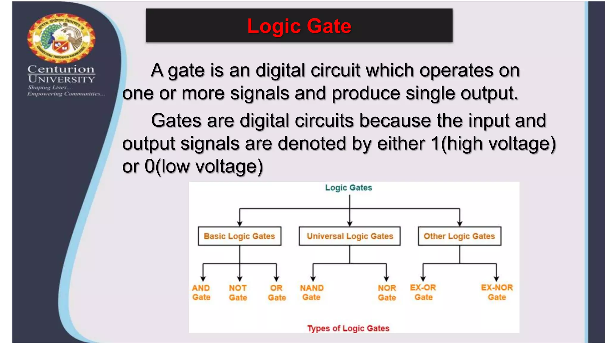
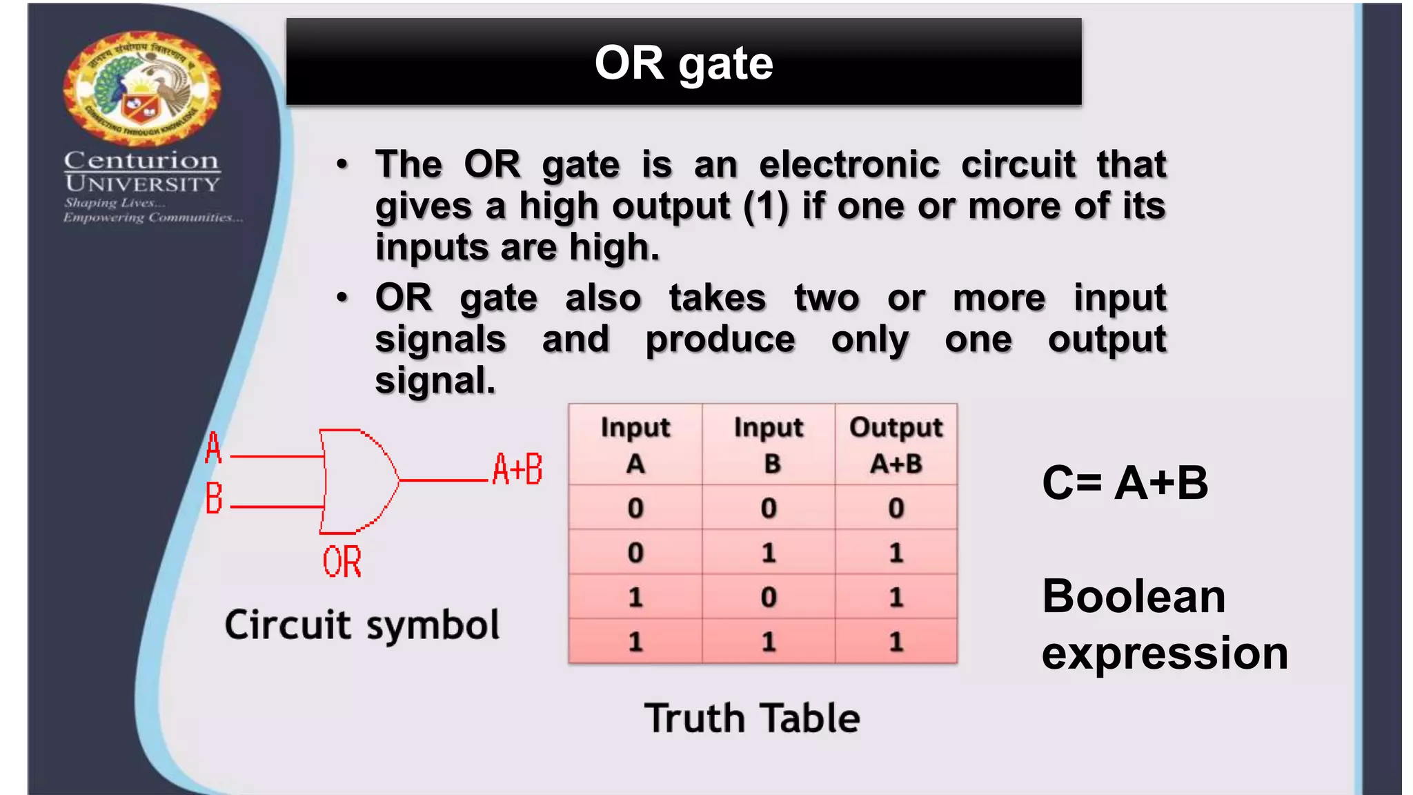
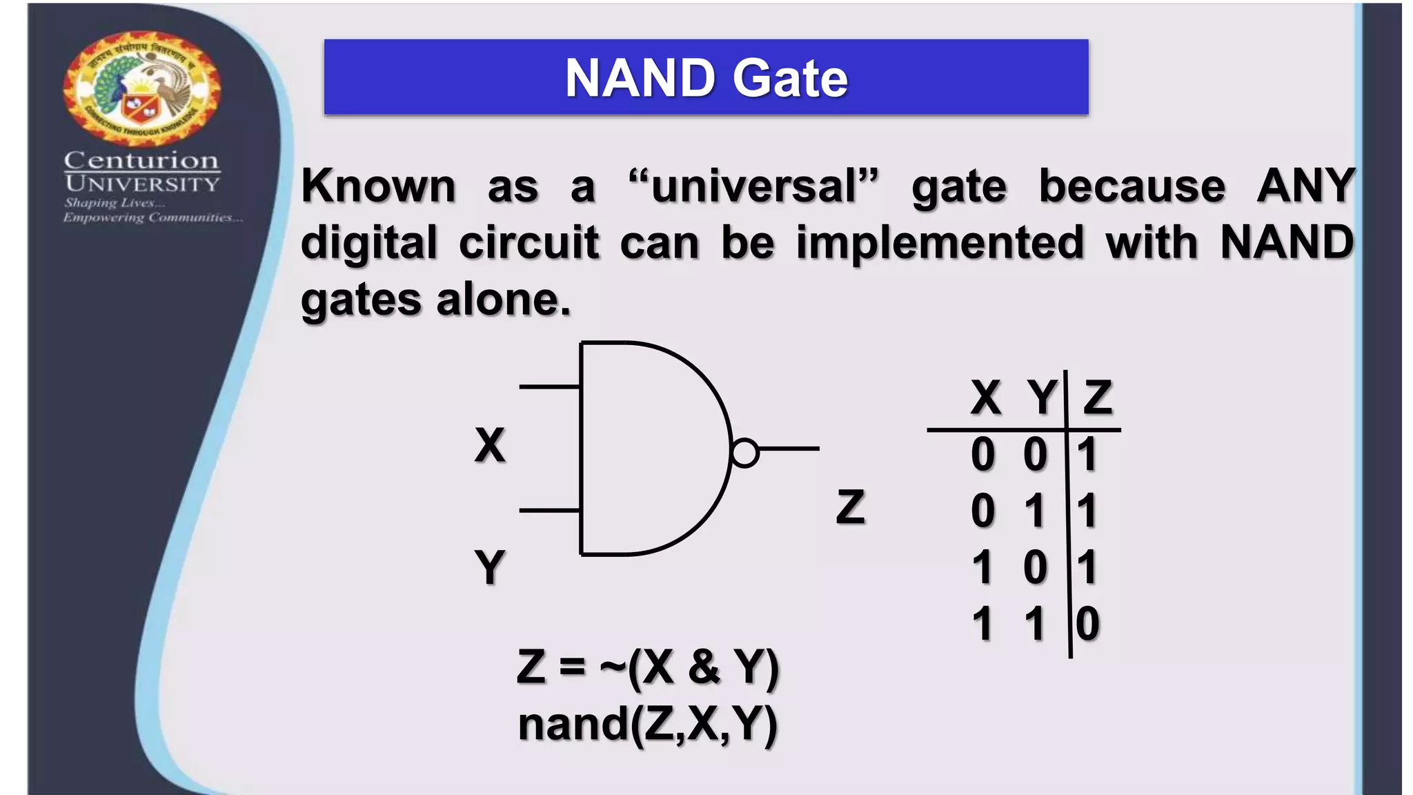
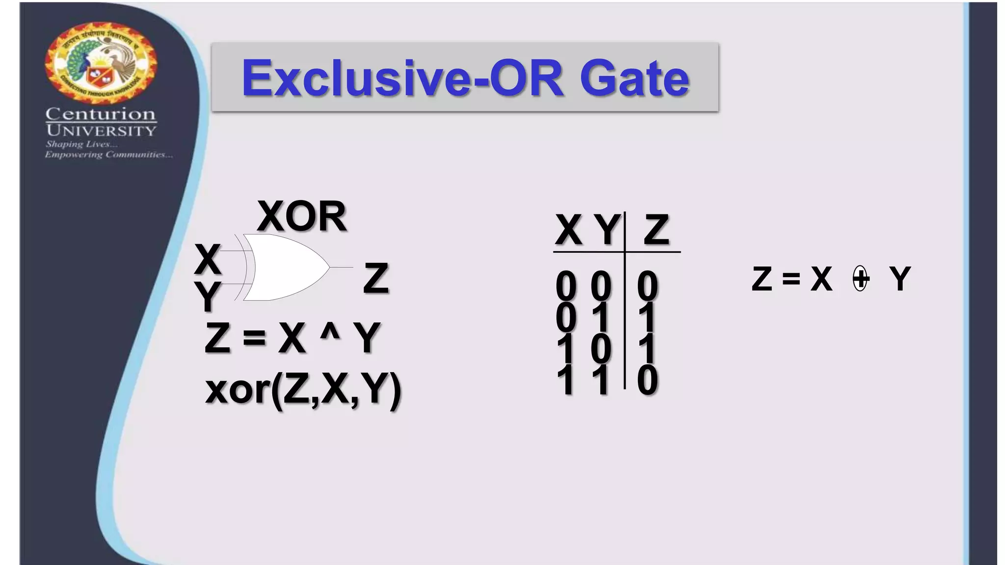
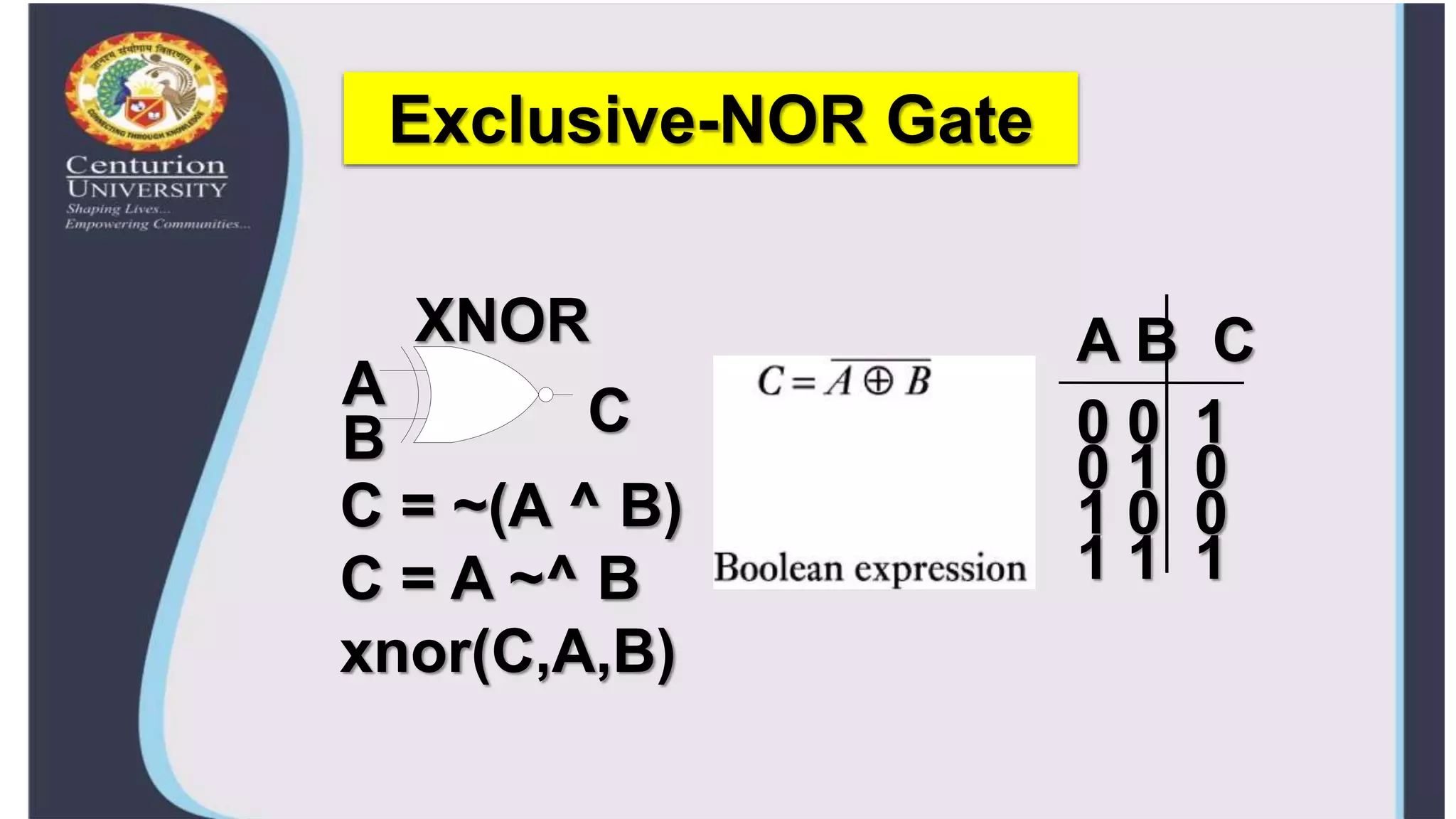
Centurion University of Technology and
Management
Topic:- LOGIC GATES
Guided By:-
Dr. Satyanarayan Padhy sir
Name:- Manish Kumar
Reg. no.:- 210101120013
Sec :- A
VLSI DESIGN
Logic Gate
A gate is an digital circuit which operates on
one or more signals and produce single output.
Gates are digital circuits because the input and
output signals are denoted by either 1(high voltage)
or 0(low voltage)
AND gate
• The AND gate is an electronic circuit that
gives a high output (1) only if all its inputs are
high.
• AND gate takes two or more input signals and
produce only one output signal.
Circuit symbol
Truth Table
AB = A . B
Boolean
expression
OR gate
• The OR gate is an electronic circuit that
gives a high output (1) if one or more of its
inputs are high.
• OR gate also takes two or more input
signals and produce only one output
signal.
C= A+B
Boolean
expression
NOT gate
• The NOT gate is an electronic circuit that gives a
high output (1) if its input is low .
• NOT gate takes only one input signal and produce
only one output signal.
• The output of NOT gate is complement of its input.
• It is also called inverter.
A = A
Boolean
expression
A logic buffer gate
NAND Gate
Known as a “universal” gate because ANY
digital circuit can be implemented with NAND
gates alone.
X
Y
Z
X Y Z
0 0 1
0 1 1
1 0 1
1 1 0
Z = ~(X & Y)
nand(Z,X,Y)
NOR Gate
NOR
A
B
C
A B C
0 0 1
0 1 0
1 0 0
1 1 0
C = ~(A | B)
nor(C,A,B)
Exclusive-OR Gate
X Y Z
XOR
X
Y Z 0 0 0
0 1 1
1 0 1
1 1 0
Z = X ^ Y
xor(Z,X,Y)
Z = X + Y
Exclusive-NOR Gate
A B C
XNOR
A
B C 0 0 1
0 1 0
1 0 0
1 1 1
C = ~(A ^ B)
C = A ~^ B
xnor(C,A,B)
Conclusion
Logic gates can be used in technologies
such as smartphones, tablets or within
memory devices. In a circuit, logic gates
will make decisions based on a
combination of digital signals coming
from its inputs. Most logic gates have
two inputs and one output. Logic gates
are based on Boolean algebra.
logic gates.pptx

logic gates.pptx

  • 1.
    Centurion University ofTechnology and Management Topic:- LOGIC GATES Guided By:- Dr. Satyanarayan Padhy sir Name:- Manish Kumar Reg. no.:- 210101120013 Sec :- A VLSI DESIGN
  • 2.
    Logic Gate A gateis an digital circuit which operates on one or more signals and produce single output. Gates are digital circuits because the input and output signals are denoted by either 1(high voltage) or 0(low voltage)
  • 3.
    AND gate • TheAND gate is an electronic circuit that gives a high output (1) only if all its inputs are high. • AND gate takes two or more input signals and produce only one output signal. Circuit symbol Truth Table AB = A . B Boolean expression
  • 4.
    OR gate • TheOR gate is an electronic circuit that gives a high output (1) if one or more of its inputs are high. • OR gate also takes two or more input signals and produce only one output signal. C= A+B Boolean expression
  • 5.
    NOT gate • TheNOT gate is an electronic circuit that gives a high output (1) if its input is low . • NOT gate takes only one input signal and produce only one output signal. • The output of NOT gate is complement of its input. • It is also called inverter. A = A Boolean expression
  • 6.
  • 7.
    NAND Gate Known asa “universal” gate because ANY digital circuit can be implemented with NAND gates alone. X Y Z X Y Z 0 0 1 0 1 1 1 0 1 1 1 0 Z = ~(X & Y) nand(Z,X,Y)
  • 8.
    NOR Gate NOR A B C A BC 0 0 1 0 1 0 1 0 0 1 1 0 C = ~(A | B) nor(C,A,B)
  • 9.
    Exclusive-OR Gate X YZ XOR X Y Z 0 0 0 0 1 1 1 0 1 1 1 0 Z = X ^ Y xor(Z,X,Y) Z = X + Y
  • 10.
    Exclusive-NOR Gate A BC XNOR A B C 0 0 1 0 1 0 1 0 0 1 1 1 C = ~(A ^ B) C = A ~^ B xnor(C,A,B)
  • 11.
    Conclusion Logic gates canbe used in technologies such as smartphones, tablets or within memory devices. In a circuit, logic gates will make decisions based on a combination of digital signals coming from its inputs. Most logic gates have two inputs and one output. Logic gates are based on Boolean algebra.