Download as PDF, PPTX
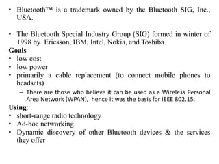
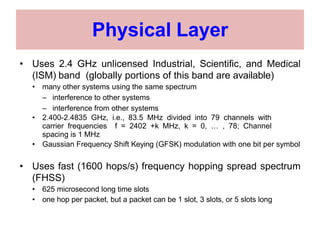
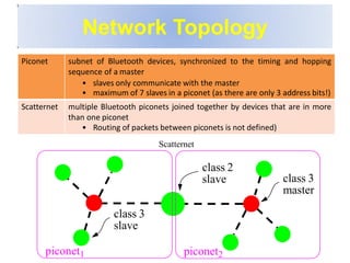


Bluetooth is a wireless technology standard that was created in 1998 to provide wireless connectivity between devices over short distances. It uses short-wavelength UHF radio waves in the ISM band from 2.4 to 2.485 GHz and employs frequency hopping spread spectrum technology to enable communication between multiple devices. Bluetooth devices can operate in piconets with one master device and up to seven active slave devices, and multiple piconets can be joined together to form scatternets. Bluetooth supports both synchronous voice links and asynchronous data links between devices.