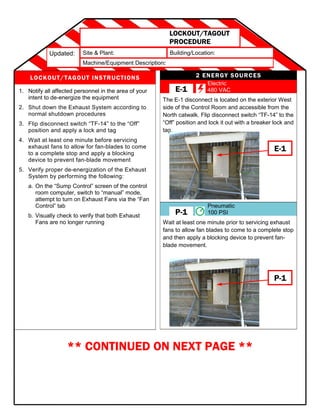
Updated: Site & Plant: Building/Location:
Machine/Equipment Description:
LOCKOUT/TAGOUT
PROCEDURE
2 ENERGY SOURCES
Electric
480 VAC
The E-1 disconnect is located on the exterior West
side of the Control Room and accessible from the
North catwalk. Flip disconnect switch “TF-14” to the
“Off” position and lock it out with a breaker lock and
tag.
Pneumatic
100 PSI
Wait at least one minute prior to servicing exhaust
fans to allow fan blades to come to a complete stop
and then apply a blocking device to prevent fan-
blade movement.
LOCKOUT/TAGOUT INSTRUCTIONS
1. Notify all affected personnel in the area of your
intent to de-energize the equipment
2. Shut down the Exhaust System according to
normal shutdown procedures
3. Flip disconnect switch “TF-14” to the “Off”
position and apply a lock and tag
4. Wait at least one minute before servicing
exhaust fans to allow for fan-blades to come
to a complete stop and apply a blocking
device to prevent fan-blade movement
5. Verify proper de-energization of the Exhaust
System by performing the following:
a. On the “Sump Control” screen of the control
room computer, switch to “manual” mode,
attempt to turn on Exhaust Fans via the “Fan
Control” tab
b. Visually check to verify that both Exhaust
Fans are no longer running
** CONTINUED ON NEXT PAGE **
E-1
E-1
P-1
P-1
Updated: Site & Plant: Building/Location:
Machine/Equipment Description:
LOCKOUT/TAGOUT
PROCEDURE
Electric
480 VAC
The E-1 disconnect is located on the exterior West
side of the Control Room and accessible from the
North catwalk. Flip disconnect switch “TF-14” to the
“Off” position and lock it out with a breaker lock and
tag.
Pneumatic
100 PSI
Wait at least one minute prior to servicing exhaust
fans to allow fan blades to come to a complete stop
and then apply a blocking device to prevent fan-
blade movement.
E-1
E-1
P-1
P-1
2 ENERGY SOURCES
Electric
480 VAC
The E-1 disconnect is located on the exterior West
side of the Control Room and accessible from the
North catwalk. Flip disconnect switch “TF-14” to the
“Off” position and lock it out with a breaker lock and
tag.
Pneumatic
100 PSI
Wait at least one minute prior to servicing exhaust
fans to allow fan blades to come to a complete stop
and then apply a blocking device to prevent fan-
blade movement.
E-1
E-1
P-1
P-1
LOCKOUT/TAGOUT REMOVAL INSTRUCTIONS
1. Ensure all tools have been removed, guards put back in place and any blocking devices have been removed
2. Confirm that all affected personnel are cleared from the machine/equipment and accounted for
3. Verify that the machine/equipment controls are in “Neutral” or “Off” positions
4. Remove Locks and tags
5. Notify all affected personnel that LOTO is complete and ready for re-energization.
6. Re-energize machine/equipment and verify functionality

Ben Version 2-page LOTO Procedure TEMPLATE

  • 1.
    Updated: Site &Plant: Building/Location: Machine/Equipment Description: LOCKOUT/TAGOUT PROCEDURE 2 ENERGY SOURCES Electric 480 VAC The E-1 disconnect is located on the exterior West side of the Control Room and accessible from the North catwalk. Flip disconnect switch “TF-14” to the “Off” position and lock it out with a breaker lock and tag. Pneumatic 100 PSI Wait at least one minute prior to servicing exhaust fans to allow fan blades to come to a complete stop and then apply a blocking device to prevent fan- blade movement. LOCKOUT/TAGOUT INSTRUCTIONS 1. Notify all affected personnel in the area of your intent to de-energize the equipment 2. Shut down the Exhaust System according to normal shutdown procedures 3. Flip disconnect switch “TF-14” to the “Off” position and apply a lock and tag 4. Wait at least one minute before servicing exhaust fans to allow for fan-blades to come to a complete stop and apply a blocking device to prevent fan-blade movement 5. Verify proper de-energization of the Exhaust System by performing the following: a. On the “Sump Control” screen of the control room computer, switch to “manual” mode, attempt to turn on Exhaust Fans via the “Fan Control” tab b. Visually check to verify that both Exhaust Fans are no longer running ** CONTINUED ON NEXT PAGE ** E-1 E-1 P-1 P-1
  • 2.
    Updated: Site &Plant: Building/Location: Machine/Equipment Description: LOCKOUT/TAGOUT PROCEDURE Electric 480 VAC The E-1 disconnect is located on the exterior West side of the Control Room and accessible from the North catwalk. Flip disconnect switch “TF-14” to the “Off” position and lock it out with a breaker lock and tag. Pneumatic 100 PSI Wait at least one minute prior to servicing exhaust fans to allow fan blades to come to a complete stop and then apply a blocking device to prevent fan- blade movement. E-1 E-1 P-1 P-1 2 ENERGY SOURCES Electric 480 VAC The E-1 disconnect is located on the exterior West side of the Control Room and accessible from the North catwalk. Flip disconnect switch “TF-14” to the “Off” position and lock it out with a breaker lock and tag. Pneumatic 100 PSI Wait at least one minute prior to servicing exhaust fans to allow fan blades to come to a complete stop and then apply a blocking device to prevent fan- blade movement. E-1 E-1 P-1 P-1 LOCKOUT/TAGOUT REMOVAL INSTRUCTIONS 1. Ensure all tools have been removed, guards put back in place and any blocking devices have been removed 2. Confirm that all affected personnel are cleared from the machine/equipment and accounted for 3. Verify that the machine/equipment controls are in “Neutral” or “Off” positions 4. Remove Locks and tags 5. Notify all affected personnel that LOTO is complete and ready for re-energization. 6. Re-energize machine/equipment and verify functionality