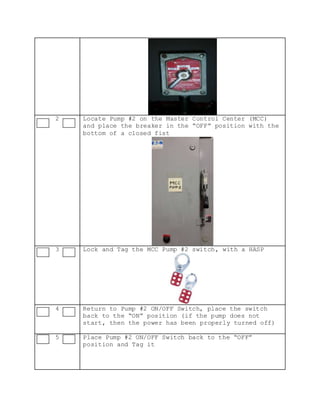
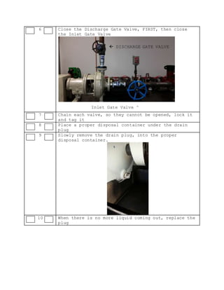
Signatures
Developed by: Landon, Amanda Date:
Reviewed by: Date:
Approved by: Date:
Title
Isolation and Lockout/Tagout of Pump #2 for maintenance
Purpose
This procedure establishes the minimum requirements for lockout
of energy sources that could cause injury to personnel and to
isolate pump #2 for maintenance. All employees shall comply with
the procedure.
Preparation for Lockout
Before you start with this procedure, make sure that you have
the proper tools. Personal Protective Equipment should consist
of a hard hat, leather gloves, steel toe boots, safety glasses
and if there is a possibility of liquid splatter, a face shield.
Specific Hazards
HAZARDS CONTROL
Electrical Make sure that the electrical box is grounded
and do not wear jewelry
Ergonomics Use good posture and watch your footing. Use
correct tools and avoid using excessive force
or repetition.
Stored Pressure Bleed pressure off slowly
Hot Fluids Wear long sleeves and consider a face shield
Procedure
Pre/Post
Checklist
Initial Pre/Post checklist to assure that each step
has been completed
Step
Pre- Post
Action
1 Locate the ON/OFF Switch for Pump #2 and place the
switch to the “OFF” position
2 Locate Pump #2 on the Master Control Center (MCC)
and place the breaker in the “OFF” position with the
bottom of a closed fist
3 Lock and Tag the MCC Pump #2 switch, with a HASP
4 Return to Pump #2 ON/OFF Switch, place the switch
back to the “ON” position (if the pump does not
start, then the power has been properly turned off)
5 Place Pump #2 ON/OFF Switch back to the “OFF”
position and Tag it
6 Close the Discharge Gate Valve, FIRST, then close
the Inlet Gate Valve
7 Chain each valve, so they cannot be opened, lock it
and tag it
8 Place a proper disposal container under the drain
plug
9 Slowly remove the drain plug, into the proper
disposal container.
10 When there is no more liquid coming out, replace the
plug
 DISCHARGE GATE VALVE
Inlet Gate Valve ^

LOTO Procedure

  • 1.
    Signatures Developed by: Landon,Amanda Date: Reviewed by: Date: Approved by: Date: Title Isolation and Lockout/Tagout of Pump #2 for maintenance Purpose This procedure establishes the minimum requirements for lockout of energy sources that could cause injury to personnel and to isolate pump #2 for maintenance. All employees shall comply with the procedure. Preparation for Lockout Before you start with this procedure, make sure that you have the proper tools. Personal Protective Equipment should consist of a hard hat, leather gloves, steel toe boots, safety glasses and if there is a possibility of liquid splatter, a face shield. Specific Hazards HAZARDS CONTROL Electrical Make sure that the electrical box is grounded and do not wear jewelry Ergonomics Use good posture and watch your footing. Use correct tools and avoid using excessive force or repetition. Stored Pressure Bleed pressure off slowly Hot Fluids Wear long sleeves and consider a face shield Procedure Pre/Post Checklist Initial Pre/Post checklist to assure that each step has been completed Step Pre- Post Action 1 Locate the ON/OFF Switch for Pump #2 and place the switch to the “OFF” position
  • 2.
    2 Locate Pump#2 on the Master Control Center (MCC) and place the breaker in the “OFF” position with the bottom of a closed fist 3 Lock and Tag the MCC Pump #2 switch, with a HASP 4 Return to Pump #2 ON/OFF Switch, place the switch back to the “ON” position (if the pump does not start, then the power has been properly turned off) 5 Place Pump #2 ON/OFF Switch back to the “OFF” position and Tag it
  • 3.
    6 Close theDischarge Gate Valve, FIRST, then close the Inlet Gate Valve 7 Chain each valve, so they cannot be opened, lock it and tag it 8 Place a proper disposal container under the drain plug 9 Slowly remove the drain plug, into the proper disposal container. 10 When there is no more liquid coming out, replace the plug  DISCHARGE GATE VALVE Inlet Gate Valve ^