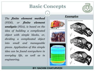
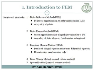
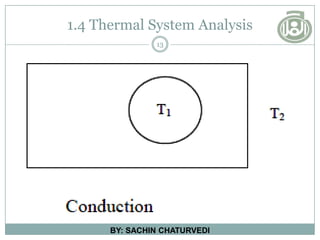
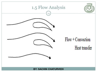
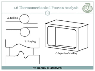
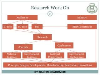
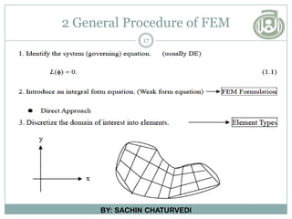
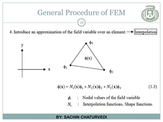
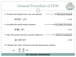
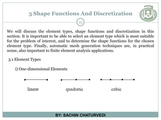
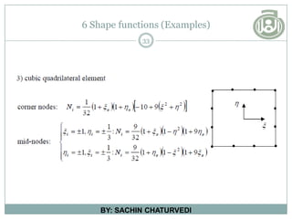
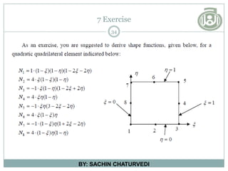
AL-FALAH SCHOOL OF ENGINEERING AND TECHNOLOGY
D E P A R T M E N T O F M E C H A N I C A L E N G I N E E R I N G
M A S T E R O F T E C H N O L O G Y
( M A C H I N E D E S I G N )
Introduction to the
Finite Element Method
BY: SACHIN CHATURVEDI
1
M. Tech (FEM - Syllabus)
2
BY: SACHIN CHATURVEDI
Paper Code: M-847-A
Theory: 100 Marks
Sessional: 50 Marks
FEM - BOOKS
3
BY: SACHIN CHATURVEDI
1. Introduction to Finite Elements in Engineering Analysis by Tirupathi R.
Chandruipatala and Ashok R. Belagundu. Prentice Hall.
2. The Finite Element Method in Engineering by S.S.Rao, Peragamon Press,
Oxford.
3. Finite Element Procedures, by Klaus Jurgen Bathi, Prentice Hall.
4. The Finite Element Method by Zienkiewicz published by Mc Graw Hill.
5. An Introduction to Finite Element Method by J.N. Reddy published by Mc
Graw Hill.
6. Fundamentals of the Finite Element Method for Heat and Fluid Flow by
Roland W. Lewis, Perumal Nithiarasu, Kankanhalli N. Seetharamu by John
Wiley.
4
Basic Concepts
The finite element method
(FEM), or finite element
analysis (FEA), is based on the
idea of building a complicated
object with simple blocks, or,
dividing a complicated object
into small and manageable
pieces. Application of this simple
idea can be found everywhere in
everyday life, as well as in
engineering.
BY: SACHIN CHATURVEDI
Examples
Best Example Of Fem
Blades in turbine engines are typical examples
5
BY: SACHIN CHATURVEDI
FEM Examples
6
BY: SACHIN CHATURVEDI
1. Introduction to FEM
7
BY: SACHIN CHATURVEDI
Numerical Methods:
1.1 Applications
8
BY: SACHIN CHATURVEDI
A diversity of specializations under the union of the mechanical engineering
discipline (such as aeronautical, biomechanical, and automotive industries)
commonly use integrated FEM in design and development of their products.
Several modern FEM packages include specific components such as thermal,
electromagnetic, fluid, and structural working environments. In a structural
simulation, FEM helps tremendously in producing stiffness and strength
visualizations and also in minimizing weight, materials, and costs.
Applications
Cont……
9
BY: SACHIN CHATURVEDI
FEM allows detailed visualization of where structures bend or twist, and
indicates the distribution of stresses and displacements. FEM software provides
a wide range of simulation options for controlling the complexity of both
modeling and analysis of a system. Similarly, the desired level of accuracy
required and associated computational time requirements can be managed
simultaneously to address most engineering applications. FEM allows entire
designs to be constructed, refined, and optimized before the design is
manufactured.
Applications
Cont……
10
BY: SACHIN CHATURVEDI
This powerful design tool has significantly improved both the standard of
engineering designs and the methodology of the design process in many
industrial applications. The introduction of FEM has substantially decreased the
time to take products from concept to the production line. It is primarily through
improved initial prototype designs using FEM that testing and development have
been accelerated. In summary, benefits of FEM include increased accuracy,
enhanced design and better insight into critical design parameters, virtual
prototyping, fewer hardware prototypes, a faster and less expensive design cycle,
increased productivity, and increased revenue.
1.2 Visualization (Applications)
11
BY: SACHIN CHATURVEDI
Visualization of how a car deforms in an asymmetrical crash using finite element analysis
1.3 Structural Analysis
12
BY: SACHIN CHATURVEDI
1.4 Thermal System Analysis
13
BY: SACHIN CHATURVEDI
1.5 Flow Analysis
14
BY: SACHIN CHATURVEDI
1.6 Thermomechanical Process Analysis
15
BY: SACHIN CHATURVEDI
B. Forging
A. Rolling
C. Injection Molding
Research Work On
16
BY: SACHIN CHATURVEDI
Industry
Academics
B. Tech R&D Department
Conferences
Journals
International
Journals
National
Journals
International
Conferences
National
Conferences
M. Tech Phd
Research
Concepts, Designs, Developments, Manufacturing, Renovation, Innovations
2 General Procedure of FEM
17
BY: SACHIN CHATURVEDI
General Procedure of FEM
18
BY: SACHIN CHATURVEDI
General Procedure of FEM
19
BY: SACHIN CHATURVEDI
2.1 Finite Element Formulations
20
BY: SACHIN CHATURVEDI
2.1.1 Direct approach for discrete systems
Direct approach has the following features:
• It applies physical concept (e.g. force equilibrium, energy conservation,
mass conservation, etc.) directly to discretized elements. It is easy in its
physical interpretation.
• It does not need elaborate sophisticated mathematical manipulation or
concept.
• Its applicability is limited to certain problems for which equilibrium or
conservation law can be easily stated in terms of physical quantities one
wants to obtain. In most cases, discretized elements are self-obvious in
the physical sense.
2.1 Finite Element Formulations
21
BY: SACHIN CHATURVEDI
2.1.2 Coordinate Transformation approach
In many cases, one can introduce a local coordinate system associated with
each element in addition to a global coordinate system. A local coordinate
system can be defined in many cases in a self-obvious way inherent to the
element itself. It is much easier to determine the stiffness matrix with
respect to the local coordinate system of an element than with respect to the
global coordinate system. The stiffness matrix with respect to the local
coordinate system is to be transformed to that with respect to the global
coordinate system before the assembly procedure.
i) Vector Transformation in 2-D.
ii) Transformation of stiffness matrix.
2.1 Finite Element Formulations
22
BY: SACHIN CHATURVEDI
2.1.3 Direct approach for Elasticity Problem (plane stress, plane strain)
In this section, we are concerned about an elastic deformation problem in
twodimensional continuous media (therefore, not a discrete system).
2.1.4 Assembly Procedure
The assembly procedure is based on compatibility and conservation law
(e.g. force balance, mass conservation and energy conservation).
2.1.5 Variational Approach in Finite Element Formulation
Differential formulation, physical phenomena can be described in terms
of minimization of total energy (or functional) associated with the
problem, which is called “variational formulation”.
2.1 Finite Element Formulations
23
BY: SACHIN CHATURVEDI
2.1.6 Principle of Minimum Total Potential Energy
There is a very important physical principle to describe a deformation
process of an elastic body, namely Principle of Minimum Total Potential
Energy, which can be summarized as below:
Finite Element Method versus Rayleigh-Ritz Method
24
BY: SACHIN CHATURVEDI
One of the historically famous approximate methods for this kind of problem is
Rayleigh-Ritz Method, and the other modern method is the Finite Element
method. Here we will discuss both methods with the comparison in mind.
i) Rayleigh-Ritz Method: This method is very simple and easy to
understand. However, it is not easy to find a family
of trial functions for the entire domain satisfying
the essential boundary conditions when geometry
is complicated.
ii) Finite Element Method: In this case, the shape functions can be found
more easily than the trial functions without
having to worry about satisfying the essential
boundary conditions, which makes FEM much
more useful than Rayleigh-Ritz Method. In this
regard, the Finite Element Method is a
modernized approximation method suitable for
computer environment.
3 Shape Functions And Discretization
25
BY: SACHIN CHATURVEDI
We will discuss the element types, shape functions and discretization in this
section. It is important to be able to select an element type which is most suitable
for the problem of interest, and to determine the shape functions for the chosen
element type. Finally, automatic mesh generation techniques are, in practical
sense, also important to finite element analysis applications.
3.1 Element Types
i) One-dimensional Elements
3 Shape Functions And Discretization
26
BY: SACHIN CHATURVEDI
ii) Two-dimensional Elements
3 Shape Functions And Discretization
27
BY: SACHIN CHATURVEDI
iii) Three-dimensional Elements
4 Natural Coordinates
28
BY: SACHIN CHATURVEDI
Note that N (x, y) in our current form is represented in terms of the nodal
coordinates (xi , yi ) and a global coordinate (x, y). One can have a better form in
terms of so-called “Natural Coordinate”, in particular for triangular type of
elements (or “Normalized Coordinate” for a quadrilateral type of elements ).
1) One-dimensional case
4 Natural Coordinates
29
BY: SACHIN CHATURVEDI
2) Two-dimensional case
3) Three-dimensional case
5 Normalized coordinate
30
BY: SACHIN CHATURVEDI
6 Shape functions (Examples)
31
BY: SACHIN CHATURVEDI
Shape functions for several quadrilateral elements are summarized below:
6 Shape functions (Examples)
32
BY: SACHIN CHATURVEDI
6 Shape functions (Examples)
33
BY: SACHIN CHATURVEDI
7 Exercise
34
BY: SACHIN CHATURVEDI
QUESTIONS
35

fem-ppt-introduction-sachin-new.pdf

  • 1.
    AL-FALAH SCHOOL OFENGINEERING AND TECHNOLOGY D E P A R T M E N T O F M E C H A N I C A L E N G I N E E R I N G M A S T E R O F T E C H N O L O G Y ( M A C H I N E D E S I G N ) Introduction to the Finite Element Method BY: SACHIN CHATURVEDI 1
  • 2.
    M. Tech (FEM- Syllabus) 2 BY: SACHIN CHATURVEDI Paper Code: M-847-A Theory: 100 Marks Sessional: 50 Marks
  • 3.
    FEM - BOOKS 3 BY:SACHIN CHATURVEDI 1. Introduction to Finite Elements in Engineering Analysis by Tirupathi R. Chandruipatala and Ashok R. Belagundu. Prentice Hall. 2. The Finite Element Method in Engineering by S.S.Rao, Peragamon Press, Oxford. 3. Finite Element Procedures, by Klaus Jurgen Bathi, Prentice Hall. 4. The Finite Element Method by Zienkiewicz published by Mc Graw Hill. 5. An Introduction to Finite Element Method by J.N. Reddy published by Mc Graw Hill. 6. Fundamentals of the Finite Element Method for Heat and Fluid Flow by Roland W. Lewis, Perumal Nithiarasu, Kankanhalli N. Seetharamu by John Wiley.
  • 4.
    4 Basic Concepts The finiteelement method (FEM), or finite element analysis (FEA), is based on the idea of building a complicated object with simple blocks, or, dividing a complicated object into small and manageable pieces. Application of this simple idea can be found everywhere in everyday life, as well as in engineering. BY: SACHIN CHATURVEDI Examples
  • 5.
    Best Example OfFem Blades in turbine engines are typical examples 5 BY: SACHIN CHATURVEDI
  • 6.
  • 7.
    1. Introduction toFEM 7 BY: SACHIN CHATURVEDI Numerical Methods:
  • 8.
    1.1 Applications 8 BY: SACHINCHATURVEDI A diversity of specializations under the union of the mechanical engineering discipline (such as aeronautical, biomechanical, and automotive industries) commonly use integrated FEM in design and development of their products. Several modern FEM packages include specific components such as thermal, electromagnetic, fluid, and structural working environments. In a structural simulation, FEM helps tremendously in producing stiffness and strength visualizations and also in minimizing weight, materials, and costs.
  • 9.
    Applications Cont…… 9 BY: SACHIN CHATURVEDI FEMallows detailed visualization of where structures bend or twist, and indicates the distribution of stresses and displacements. FEM software provides a wide range of simulation options for controlling the complexity of both modeling and analysis of a system. Similarly, the desired level of accuracy required and associated computational time requirements can be managed simultaneously to address most engineering applications. FEM allows entire designs to be constructed, refined, and optimized before the design is manufactured.
  • 10.
    Applications Cont…… 10 BY: SACHIN CHATURVEDI Thispowerful design tool has significantly improved both the standard of engineering designs and the methodology of the design process in many industrial applications. The introduction of FEM has substantially decreased the time to take products from concept to the production line. It is primarily through improved initial prototype designs using FEM that testing and development have been accelerated. In summary, benefits of FEM include increased accuracy, enhanced design and better insight into critical design parameters, virtual prototyping, fewer hardware prototypes, a faster and less expensive design cycle, increased productivity, and increased revenue.
  • 11.
    1.2 Visualization (Applications) 11 BY:SACHIN CHATURVEDI Visualization of how a car deforms in an asymmetrical crash using finite element analysis
  • 12.
  • 13.
    1.4 Thermal SystemAnalysis 13 BY: SACHIN CHATURVEDI
  • 14.
    1.5 Flow Analysis 14 BY:SACHIN CHATURVEDI
  • 15.
    1.6 Thermomechanical ProcessAnalysis 15 BY: SACHIN CHATURVEDI B. Forging A. Rolling C. Injection Molding
  • 16.
    Research Work On 16 BY:SACHIN CHATURVEDI Industry Academics B. Tech R&D Department Conferences Journals International Journals National Journals International Conferences National Conferences M. Tech Phd Research Concepts, Designs, Developments, Manufacturing, Renovation, Innovations
  • 17.
    2 General Procedureof FEM 17 BY: SACHIN CHATURVEDI
  • 18.
    General Procedure ofFEM 18 BY: SACHIN CHATURVEDI
  • 19.
    General Procedure ofFEM 19 BY: SACHIN CHATURVEDI
  • 20.
    2.1 Finite ElementFormulations 20 BY: SACHIN CHATURVEDI 2.1.1 Direct approach for discrete systems Direct approach has the following features: • It applies physical concept (e.g. force equilibrium, energy conservation, mass conservation, etc.) directly to discretized elements. It is easy in its physical interpretation. • It does not need elaborate sophisticated mathematical manipulation or concept. • Its applicability is limited to certain problems for which equilibrium or conservation law can be easily stated in terms of physical quantities one wants to obtain. In most cases, discretized elements are self-obvious in the physical sense.
  • 21.
    2.1 Finite ElementFormulations 21 BY: SACHIN CHATURVEDI 2.1.2 Coordinate Transformation approach In many cases, one can introduce a local coordinate system associated with each element in addition to a global coordinate system. A local coordinate system can be defined in many cases in a self-obvious way inherent to the element itself. It is much easier to determine the stiffness matrix with respect to the local coordinate system of an element than with respect to the global coordinate system. The stiffness matrix with respect to the local coordinate system is to be transformed to that with respect to the global coordinate system before the assembly procedure. i) Vector Transformation in 2-D. ii) Transformation of stiffness matrix.
  • 22.
    2.1 Finite ElementFormulations 22 BY: SACHIN CHATURVEDI 2.1.3 Direct approach for Elasticity Problem (plane stress, plane strain) In this section, we are concerned about an elastic deformation problem in twodimensional continuous media (therefore, not a discrete system). 2.1.4 Assembly Procedure The assembly procedure is based on compatibility and conservation law (e.g. force balance, mass conservation and energy conservation). 2.1.5 Variational Approach in Finite Element Formulation Differential formulation, physical phenomena can be described in terms of minimization of total energy (or functional) associated with the problem, which is called “variational formulation”.
  • 23.
    2.1 Finite ElementFormulations 23 BY: SACHIN CHATURVEDI 2.1.6 Principle of Minimum Total Potential Energy There is a very important physical principle to describe a deformation process of an elastic body, namely Principle of Minimum Total Potential Energy, which can be summarized as below:
  • 24.
    Finite Element Methodversus Rayleigh-Ritz Method 24 BY: SACHIN CHATURVEDI One of the historically famous approximate methods for this kind of problem is Rayleigh-Ritz Method, and the other modern method is the Finite Element method. Here we will discuss both methods with the comparison in mind. i) Rayleigh-Ritz Method: This method is very simple and easy to understand. However, it is not easy to find a family of trial functions for the entire domain satisfying the essential boundary conditions when geometry is complicated. ii) Finite Element Method: In this case, the shape functions can be found more easily than the trial functions without having to worry about satisfying the essential boundary conditions, which makes FEM much more useful than Rayleigh-Ritz Method. In this regard, the Finite Element Method is a modernized approximation method suitable for computer environment.
  • 25.
    3 Shape FunctionsAnd Discretization 25 BY: SACHIN CHATURVEDI We will discuss the element types, shape functions and discretization in this section. It is important to be able to select an element type which is most suitable for the problem of interest, and to determine the shape functions for the chosen element type. Finally, automatic mesh generation techniques are, in practical sense, also important to finite element analysis applications. 3.1 Element Types i) One-dimensional Elements
  • 26.
    3 Shape FunctionsAnd Discretization 26 BY: SACHIN CHATURVEDI ii) Two-dimensional Elements
  • 27.
    3 Shape FunctionsAnd Discretization 27 BY: SACHIN CHATURVEDI iii) Three-dimensional Elements
  • 28.
    4 Natural Coordinates 28 BY:SACHIN CHATURVEDI Note that N (x, y) in our current form is represented in terms of the nodal coordinates (xi , yi ) and a global coordinate (x, y). One can have a better form in terms of so-called “Natural Coordinate”, in particular for triangular type of elements (or “Normalized Coordinate” for a quadrilateral type of elements ). 1) One-dimensional case
  • 29.
    4 Natural Coordinates 29 BY:SACHIN CHATURVEDI 2) Two-dimensional case 3) Three-dimensional case
  • 30.
  • 31.
    6 Shape functions(Examples) 31 BY: SACHIN CHATURVEDI Shape functions for several quadrilateral elements are summarized below:
  • 32.
    6 Shape functions(Examples) 32 BY: SACHIN CHATURVEDI
  • 33.
    6 Shape functions(Examples) 33 BY: SACHIN CHATURVEDI
  • 34.
  • 35.