Downloaded 735 times
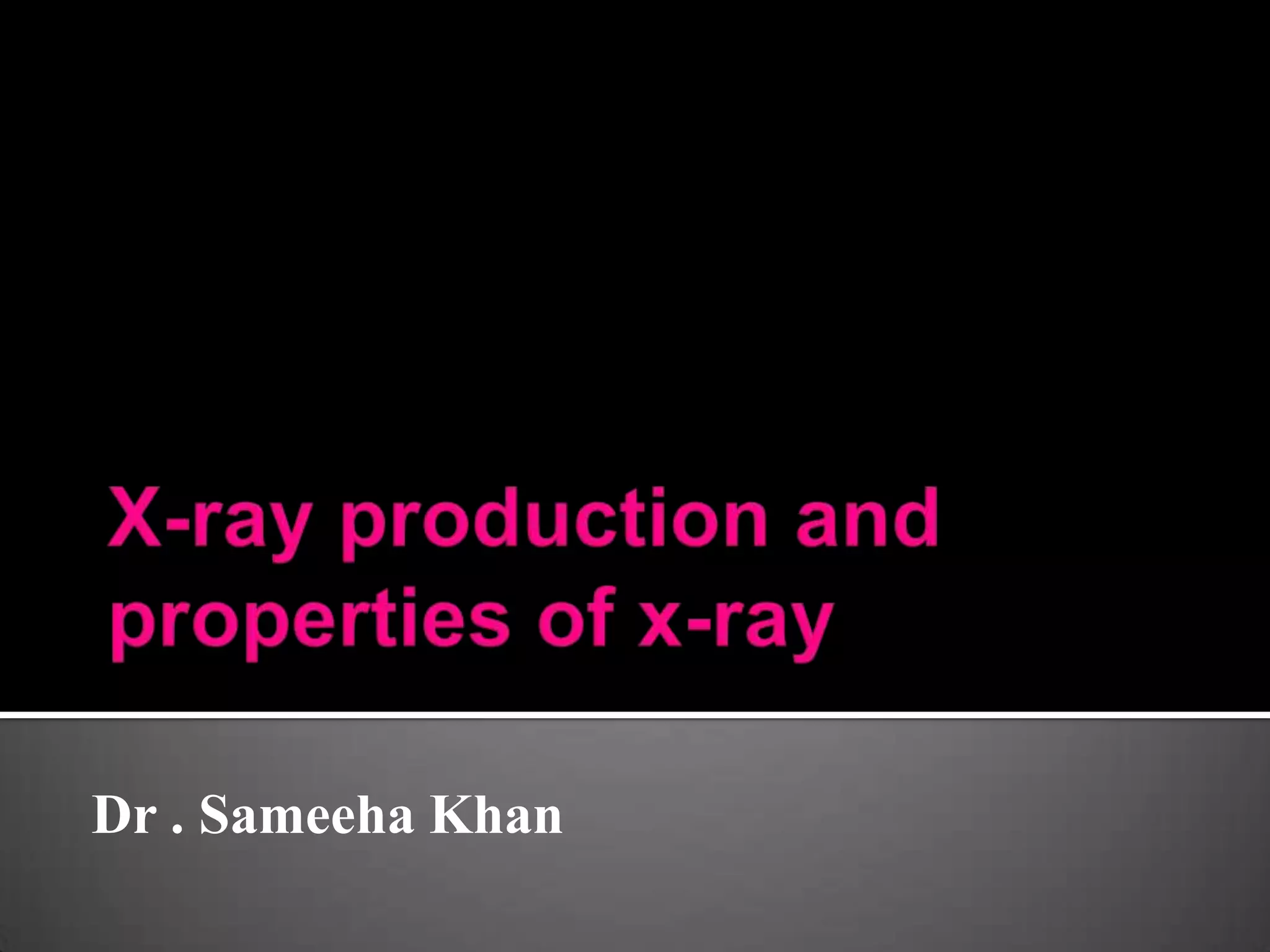
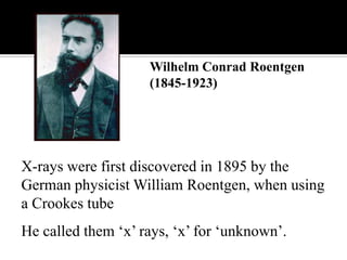

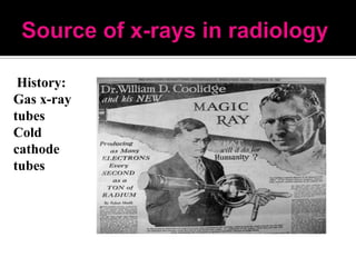
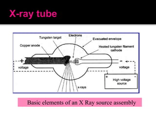


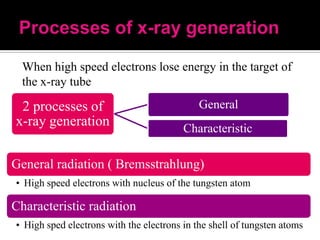
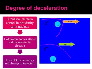
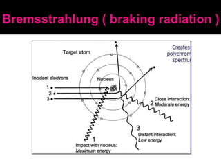
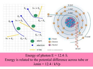
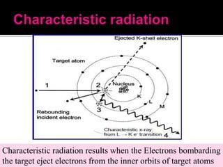
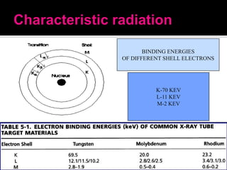
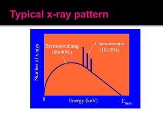


Wilhelm Roentgen discovered X-rays in 1895 while experimenting with Crookes tubes. He called them "x-rays" as the nature of the radiation was unknown. The first X-ray photograph was of his wife Bertha's hand. X-rays are a form of electromagnetic radiation with much shorter wavelengths than visible light, in the range of 0.5-2.5 angstroms. They can be considered as both waves and particles called photons. X-rays are generated in an X-ray tube when high speed electrons interact with and lose kinetic energy in the target material, usually tungsten. This produces bremsstrahlung or braking radiation and characteristic radiation when electrons change energy levels within


