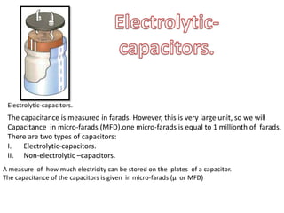
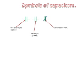
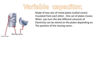
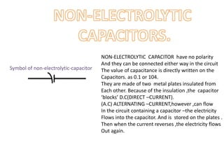
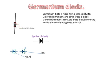
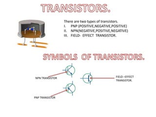
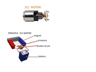
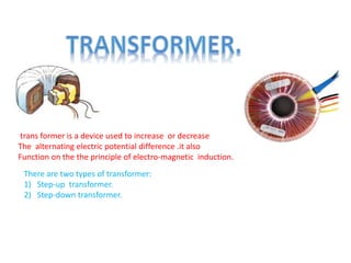
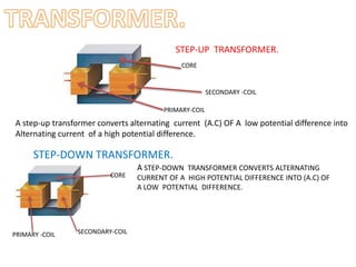
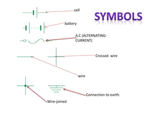
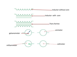
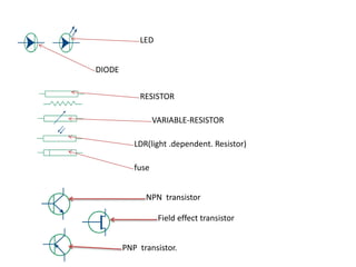
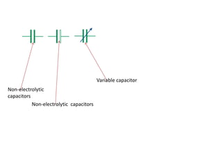
INDEX ELECTRONICS.
1. CAPACITORS
2. DIODE
3. TRANSISTOR
4. RESISTOR
5. LED’S
6. D.C MOTOR
7. TRANSFORMER
8. SYMBOLS.
9. MOTHER –BOARD
PARTS.
Electrolytic-capacitors.
The capacitance is measured in farads. However, this is very large unit, so we will
Capacitance in micro-farads.(MFD).one micro-farads is equal to 1 millionth of farads.
There are two types of capacitors:
I. Electrolytic-capacitors.
II. Non-electrolytic –capacitors.
A measure of how much electricity can be stored on the plates of a capacitor.
The capacitance of the capacitors is given in micro-farads (µ or MFD)
Variable capacitors.
electrolytic
Capacitor.
Non-electrolytic
capacitor
Moving-vanes.
Fixed –vanes.
Made of two sets of metal plates (called vanes)
Insulated from each other . One set of plates moves
When you turn the dial different amounts of
Electricity can be stored on the plates depending on
The position of the moving vanes .
NON-ELECTROLYTIC CAPACITOR have no polarity
And they can be connected either way in the circuit
The value of capacitance is directly written on the
Capacitors. as 0.1 or 104.
They are made of two metal plates insulated from
Each other. Because of the insulation ,the capacitor
‘blocks’ D.C(DIRECT –CURRENT).
(A.C) ALTERNATING –CURRENT,however ,can flow
In the circuit containing a capacitor –the electricity
Flows into the capacitor. And is stored on the plates .
Then when the current reverses ,the electricity flows
Out again.
Symbol of non-electrolytic-capacitor
Germanium diode.
Germanium diode is made from a semi-conductor
Material (germanium),and other types of diode
May be made from silicon .the diode allows electricity
To flow from only through one direction.
Symbol of diode.
LED
DIODE
There are two types of transistors.
I. PNP (POSITIVE,NEGATIVE,POSITIVE)
II. NPN(NEGATIVE,POSITIVE,NEGATIVE)
III. FIELD- EFFECT TRANSISTOR.
NPN TRANSISTOR
PNP TRANSISTOR
FIELD –EFFECT
TRANSISTOR.
TRANSISTORS are very important in electronics circuits . The word transistor is derived from combining
Two words, transfer resistor. Namely, transistor has three parts.
1) EMITTER
2) BASE
3) COLLECTOR
TRANSISTOR
Transistors are used to amplify tiny or weak electrical signals. They are also used as
Switches ,they are also used as oscillator.
The base is much thinner than the emitter while collector is wider than both .
The sections of transistor are made up of two types of semiconductors , N type
Semiconductor are separated by a P type semiconductors .the reverse is true for
PNP TYPE transistor.
EMITTER: the section on one side that supplies carries is called as emitter.
For NPN type transistor, it supplies electrons . Emitter is always forward biased
With respect to base.
COLLECTOR:the section on the other side that collects the charges is called as collector.
The collector is always reverse biased .its function is to remove charges from is to
Remove charges from its junction with the respect to base.
BASE: the middle section which forms two PN junctions between the emitter and
Collector is called the base .the base-collector junction is reverse biased and
Provides high resistance in the collector circuit. Transistor raises the strength of weak
Signal and thus acts as a amplifier .the weak signal is applied in the between emitter –
Base junction and output taken across the load RC connected in the collector circuit .
A (D.C ) voltage is applied in the input circuit forward biased .as the input circuit has low –
Resistance ,a small change in signal voltage causes an appreciable change in emitter
Current. This causes almost same change in collector current due to transistor action .
The collector current flowing through a high load resistance RC produces large voltage
Across it. Thus a weak signal applied in the input circuit appears in the amplified form
In the collector circuit.
SYMBOL FOR REPRESENTING RESISTANCE
Ώ,EG:Ώ100 K.
Resistor.
Resistor are components that have a predetermined resistance . Resistance determines
How much current will flow through a component . Resistor are used to control voltage
And current .a very high resistance allows very little current to flow. A low resistance
Allows a large amount of current to flow .resistor has two terminals .resistance is given in units
of OHMS . Common resistor values are from 100 ohms to 100,000 ohms .
1000 OHMS IS EQUAL TO 1 KILO OHM AND 1000 KILO OHMS MAKES 1 MEGA OHM.
Each resistor is marked with coloured stripes to indicate it’s resistance .it has 4 coloured rings.
The value of a resistor a can be found out by using the colour code .
You will find that 4 rings on the resistor, ring on one end is either golden or silver coloured .
Tolerance of GOLD=5%
Tolerance of silver=10%
(p.t.o) we must find the resistance of the resistor by using respective table on next slide.
Colour code Correspondin
g number.
C5olour code. Correspondin
g number.
black 0 Green 5
Brown 1 Blue 6
red 2 Violet 7
orange 3 Grey 8
yellow 4 white 9
Tolerance strip.
Number of zeros.Second digit
First digit
Calculate the value of a resistor using the
Colour stripes on the resistor, use the colour
Code table.
PROCEDURE:
STEP 1 : TURN THE RESISTOR SO THAT THE GOLD OR
SILVER STRIPE IS ST THE RIGHT END OF THE RESISTOR.
STEP 2 : LOOK AT THE COLOUR OF THE FIRST TWO
STRIPES ON THE LEFT END . THESE CORRESPOND TO
THE FIRST TWO DIGITS GIVEN IN THE RESISTOR COLOUR
CODE TABLEAND DETERMINE FIRST TWO DIGITS.
STEP3: LOOK AT THIRD STRIPE FROM THE LEFT.THIS
CORRESPONDS TO NUMBER OF ZEROS TO BE PLACED
AFTER FIRST TWO DIGITS.THIS IS VALUE OF RESISTOR IN
OHMS.
STEP 4: THE FOURTH STRIPE INDICATES THE
ACCURACY OF ARESISTOR .A GOLD STRIPE MEANS THE
{VALUE OF THE RESISTANCE MAY VARY 5% AND
SILVER STRIPE MEANS THE VALUE OF RESISTANCE MAY
VARY 10%}
RESISTOR
VARIABLE- RESISTOR
(L D R) light dependent-
Resistor.
fuse
LIGHT DEPENDENT RESISTOR
(L D R)
THESE RESISTOR WHOSE RESISTANCE DEPENDS
ON THE LIGHT FALLING ON THEM .THEY OFFER
MAXIMUM RESISTANCE (2 TO 5 MEGA OHMS)
WHEN THERE IS NO LIGHT FALLING ON THEM .
WHEN THE LIGHT IS BRIGHT ,THEIR RESISTANCE IS
AS LOW AS 150 OHMS. THIS MAKES THIS DEVICE
USEFUL TO SENSE THE LIGHT .THEY DO NOT HAVE
POLARITY SO YHEY CAN BE CONNECTED EITHER
WAY IN THE CIRCUIT .
L E D(light emitting diode) they emit light when forward biased.
Threshold voltage of (LED) is 1.6 to 2.4
A current of 0,02 amps (20 mA) to 0.04 amps (40 mA) is good range for led
Led’s never burn out less their current limit is passed.
They have positive leg called anode and negative leg cathode .
Remember that there is no limit the current so a resist must be used
In series with the led;s to avoid destroying it.
D.C MOTOR
PRINCIPLE :D.C MOTOR
magnet
armature
Carbon brush
battery
trans former is a device used to increase or decrease
The alternating electric potential difference .it also
Function on the the principle of electro-magnetic induction.
There are two types of transformer:
1) Step-up transformer.
2) Step-down transformer.
STEP-UP TRANSFORMER.
CORE
SECONDARY -COIL
PRIMARY-COIL
A step-up transformer converts alternating current (A.C) OF A low potential difference into
Alternating current of a high potential difference.
STEP-DOWN TRANSFORMER.
CORE
SECONDARY-COILPRIMARY -COIL
A STEP-DOWN TRANSFORMER CONVERTS ALTERNATING
CURRENT OF A HIGH POTENTIAL DIFFERENCE INTO (A.C) OF
A LOW POTENTIAL DIFFERENCE.
cell
battery
A.C (ALTERNATING-
CURRENT)
Crossed wire
wire
Connection to earth.
Wire-joined
Inductor without core
Inductor with core
Trans former.
Ma
ammeter
galvanometer
voltmeter
milliammeter
LED
DIODE
RESISTOR
VARIABLE-RESISTOR
LDR(light .dependent. Resistor)
fuse
NPN transistor
Field effect transistor
PNP transistor.
Non-electrolytic capacitors
Variable capacitor
Non-electrolytic
capacitors
Basic Electronics
Basic Electronics

Basic Electronics

  • 2.
    INDEX ELECTRONICS. 1. CAPACITORS 2.DIODE 3. TRANSISTOR 4. RESISTOR 5. LED’S 6. D.C MOTOR 7. TRANSFORMER 8. SYMBOLS. 9. MOTHER –BOARD PARTS.
  • 4.
    Electrolytic-capacitors. The capacitance ismeasured in farads. However, this is very large unit, so we will Capacitance in micro-farads.(MFD).one micro-farads is equal to 1 millionth of farads. There are two types of capacitors: I. Electrolytic-capacitors. II. Non-electrolytic –capacitors. A measure of how much electricity can be stored on the plates of a capacitor. The capacitance of the capacitors is given in micro-farads (µ or MFD)
  • 5.
  • 6.
    Moving-vanes. Fixed –vanes. Made oftwo sets of metal plates (called vanes) Insulated from each other . One set of plates moves When you turn the dial different amounts of Electricity can be stored on the plates depending on The position of the moving vanes .
  • 7.
    NON-ELECTROLYTIC CAPACITOR haveno polarity And they can be connected either way in the circuit The value of capacitance is directly written on the Capacitors. as 0.1 or 104. They are made of two metal plates insulated from Each other. Because of the insulation ,the capacitor ‘blocks’ D.C(DIRECT –CURRENT). (A.C) ALTERNATING –CURRENT,however ,can flow In the circuit containing a capacitor –the electricity Flows into the capacitor. And is stored on the plates . Then when the current reverses ,the electricity flows Out again. Symbol of non-electrolytic-capacitor
  • 9.
    Germanium diode. Germanium diodeis made from a semi-conductor Material (germanium),and other types of diode May be made from silicon .the diode allows electricity To flow from only through one direction. Symbol of diode. LED DIODE
  • 11.
    There are twotypes of transistors. I. PNP (POSITIVE,NEGATIVE,POSITIVE) II. NPN(NEGATIVE,POSITIVE,NEGATIVE) III. FIELD- EFFECT TRANSISTOR. NPN TRANSISTOR PNP TRANSISTOR FIELD –EFFECT TRANSISTOR.
  • 12.
    TRANSISTORS are veryimportant in electronics circuits . The word transistor is derived from combining Two words, transfer resistor. Namely, transistor has three parts. 1) EMITTER 2) BASE 3) COLLECTOR TRANSISTOR
  • 13.
    Transistors are usedto amplify tiny or weak electrical signals. They are also used as Switches ,they are also used as oscillator. The base is much thinner than the emitter while collector is wider than both . The sections of transistor are made up of two types of semiconductors , N type Semiconductor are separated by a P type semiconductors .the reverse is true for PNP TYPE transistor. EMITTER: the section on one side that supplies carries is called as emitter. For NPN type transistor, it supplies electrons . Emitter is always forward biased With respect to base. COLLECTOR:the section on the other side that collects the charges is called as collector. The collector is always reverse biased .its function is to remove charges from is to Remove charges from its junction with the respect to base. BASE: the middle section which forms two PN junctions between the emitter and Collector is called the base .the base-collector junction is reverse biased and Provides high resistance in the collector circuit. Transistor raises the strength of weak Signal and thus acts as a amplifier .the weak signal is applied in the between emitter – Base junction and output taken across the load RC connected in the collector circuit . A (D.C ) voltage is applied in the input circuit forward biased .as the input circuit has low – Resistance ,a small change in signal voltage causes an appreciable change in emitter Current. This causes almost same change in collector current due to transistor action . The collector current flowing through a high load resistance RC produces large voltage Across it. Thus a weak signal applied in the input circuit appears in the amplified form In the collector circuit.
  • 15.
    SYMBOL FOR REPRESENTINGRESISTANCE Ώ,EG:Ώ100 K. Resistor. Resistor are components that have a predetermined resistance . Resistance determines How much current will flow through a component . Resistor are used to control voltage And current .a very high resistance allows very little current to flow. A low resistance Allows a large amount of current to flow .resistor has two terminals .resistance is given in units of OHMS . Common resistor values are from 100 ohms to 100,000 ohms . 1000 OHMS IS EQUAL TO 1 KILO OHM AND 1000 KILO OHMS MAKES 1 MEGA OHM. Each resistor is marked with coloured stripes to indicate it’s resistance .it has 4 coloured rings. The value of a resistor a can be found out by using the colour code . You will find that 4 rings on the resistor, ring on one end is either golden or silver coloured . Tolerance of GOLD=5% Tolerance of silver=10% (p.t.o) we must find the resistance of the resistor by using respective table on next slide.
  • 16.
    Colour code Correspondin gnumber. C5olour code. Correspondin g number. black 0 Green 5 Brown 1 Blue 6 red 2 Violet 7 orange 3 Grey 8 yellow 4 white 9
  • 17.
    Tolerance strip. Number ofzeros.Second digit First digit Calculate the value of a resistor using the Colour stripes on the resistor, use the colour Code table. PROCEDURE: STEP 1 : TURN THE RESISTOR SO THAT THE GOLD OR SILVER STRIPE IS ST THE RIGHT END OF THE RESISTOR. STEP 2 : LOOK AT THE COLOUR OF THE FIRST TWO STRIPES ON THE LEFT END . THESE CORRESPOND TO THE FIRST TWO DIGITS GIVEN IN THE RESISTOR COLOUR CODE TABLEAND DETERMINE FIRST TWO DIGITS. STEP3: LOOK AT THIRD STRIPE FROM THE LEFT.THIS CORRESPONDS TO NUMBER OF ZEROS TO BE PLACED AFTER FIRST TWO DIGITS.THIS IS VALUE OF RESISTOR IN OHMS. STEP 4: THE FOURTH STRIPE INDICATES THE ACCURACY OF ARESISTOR .A GOLD STRIPE MEANS THE {VALUE OF THE RESISTANCE MAY VARY 5% AND SILVER STRIPE MEANS THE VALUE OF RESISTANCE MAY VARY 10%}
  • 18.
    RESISTOR VARIABLE- RESISTOR (L DR) light dependent- Resistor. fuse LIGHT DEPENDENT RESISTOR (L D R) THESE RESISTOR WHOSE RESISTANCE DEPENDS ON THE LIGHT FALLING ON THEM .THEY OFFER MAXIMUM RESISTANCE (2 TO 5 MEGA OHMS) WHEN THERE IS NO LIGHT FALLING ON THEM . WHEN THE LIGHT IS BRIGHT ,THEIR RESISTANCE IS AS LOW AS 150 OHMS. THIS MAKES THIS DEVICE USEFUL TO SENSE THE LIGHT .THEY DO NOT HAVE POLARITY SO YHEY CAN BE CONNECTED EITHER WAY IN THE CIRCUIT .
  • 20.
    L E D(lightemitting diode) they emit light when forward biased. Threshold voltage of (LED) is 1.6 to 2.4 A current of 0,02 amps (20 mA) to 0.04 amps (40 mA) is good range for led Led’s never burn out less their current limit is passed. They have positive leg called anode and negative leg cathode . Remember that there is no limit the current so a resist must be used In series with the led;s to avoid destroying it.
  • 21.
    D.C MOTOR PRINCIPLE :D.CMOTOR magnet armature Carbon brush battery
  • 22.
    trans former isa device used to increase or decrease The alternating electric potential difference .it also Function on the the principle of electro-magnetic induction. There are two types of transformer: 1) Step-up transformer. 2) Step-down transformer.
  • 24.
    STEP-UP TRANSFORMER. CORE SECONDARY -COIL PRIMARY-COIL Astep-up transformer converts alternating current (A.C) OF A low potential difference into Alternating current of a high potential difference. STEP-DOWN TRANSFORMER. CORE SECONDARY-COILPRIMARY -COIL A STEP-DOWN TRANSFORMER CONVERTS ALTERNATING CURRENT OF A HIGH POTENTIAL DIFFERENCE INTO (A.C) OF A LOW POTENTIAL DIFFERENCE.
  • 26.
  • 27.
    Inductor without core Inductorwith core Trans former. Ma ammeter galvanometer voltmeter milliammeter
  • 28.
  • 29.