The document discusses spur gears, including definitions, types, classifications, terminology, design procedure, materials, and manufacturing methods. Some key points:
- Spur gears are circular gears with straight teeth used to transmit motion between parallel shafts.
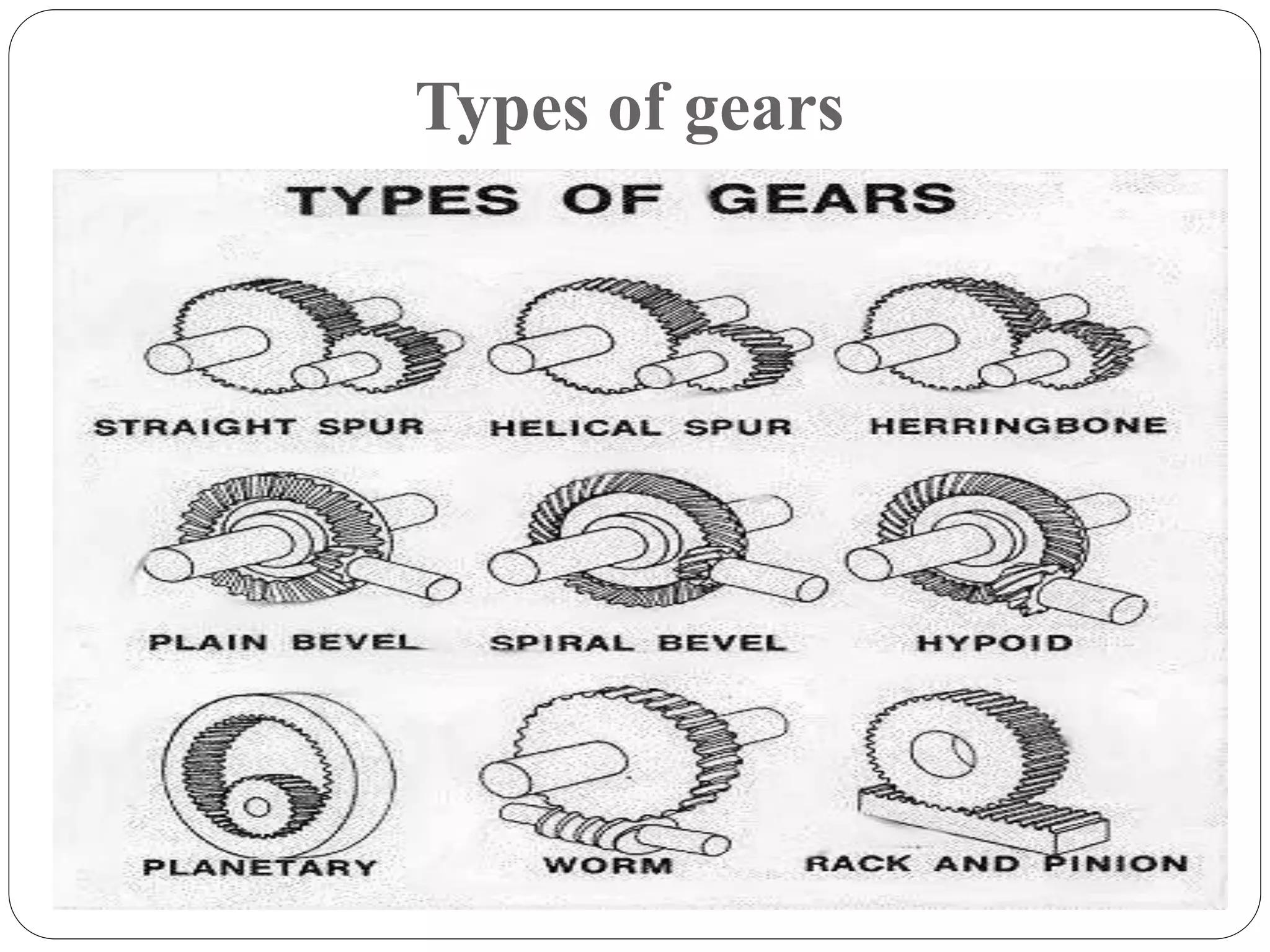
- Gears can be classified based on shaft position (parallel or intersecting), motion (fixed or planetary), peripheral speed, and tooth position (straight, helical, herringbone).
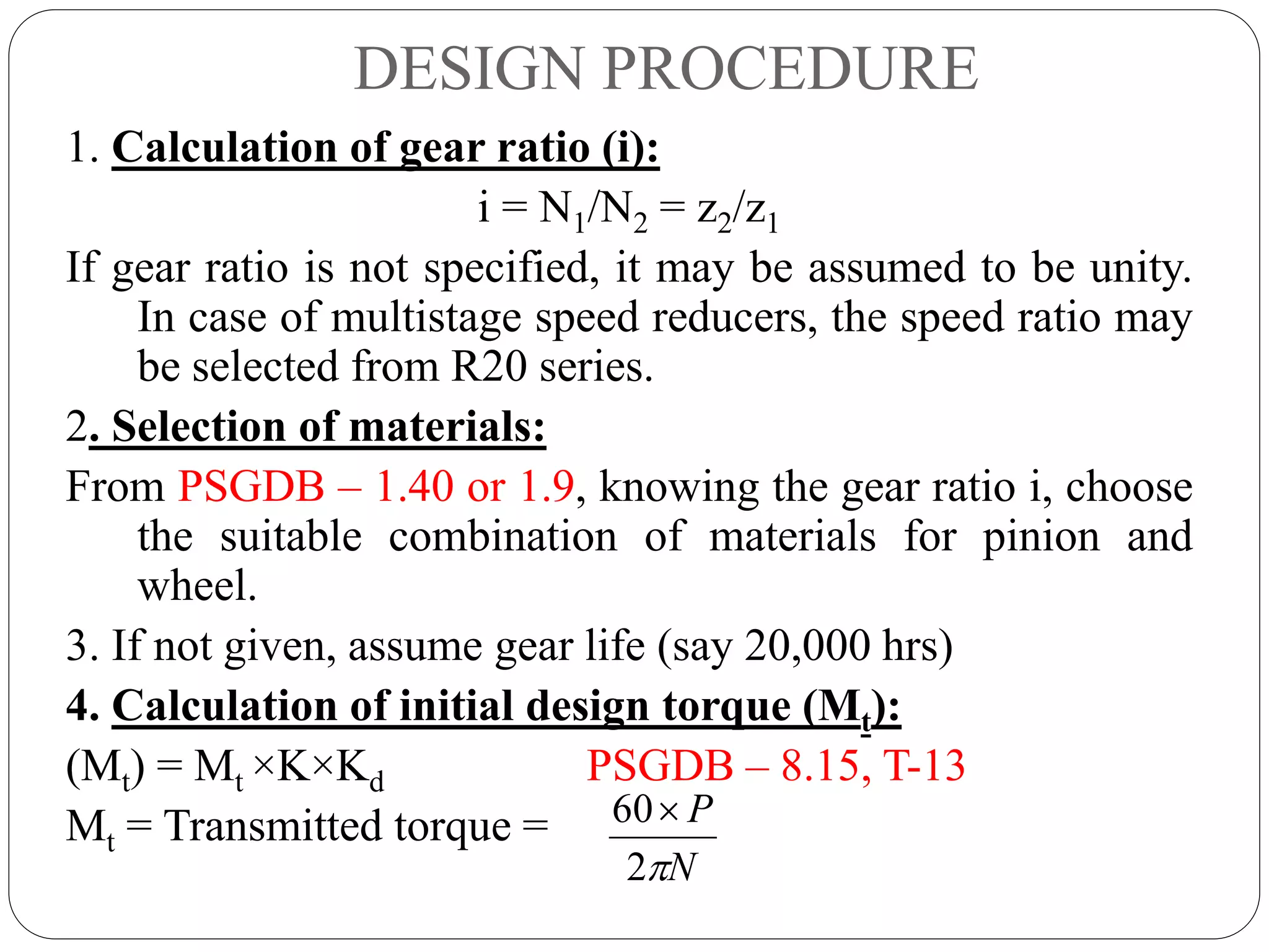
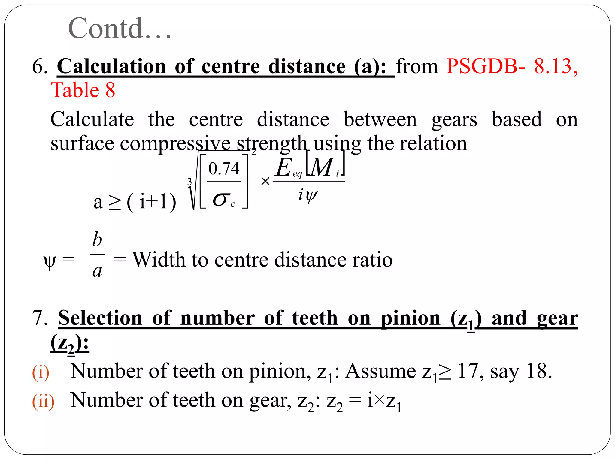
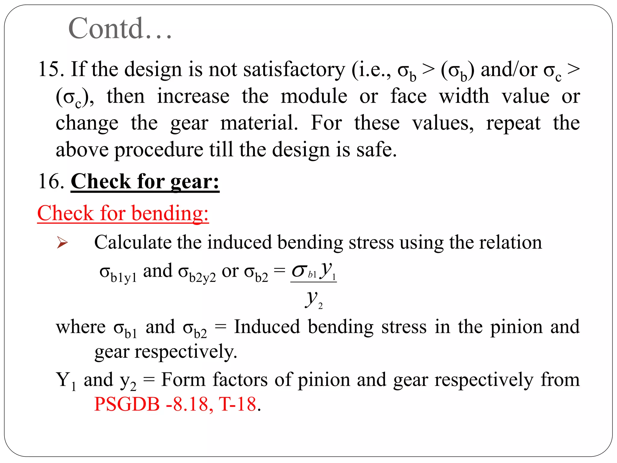
- Design of spur gears involves calculating torque, selecting materials, number of teeth, module, center distance, face width, and checking for bending and contact stresses.
- Common gear materials include steel, cast iron, and bronze. Manufacturing methods include milling, h