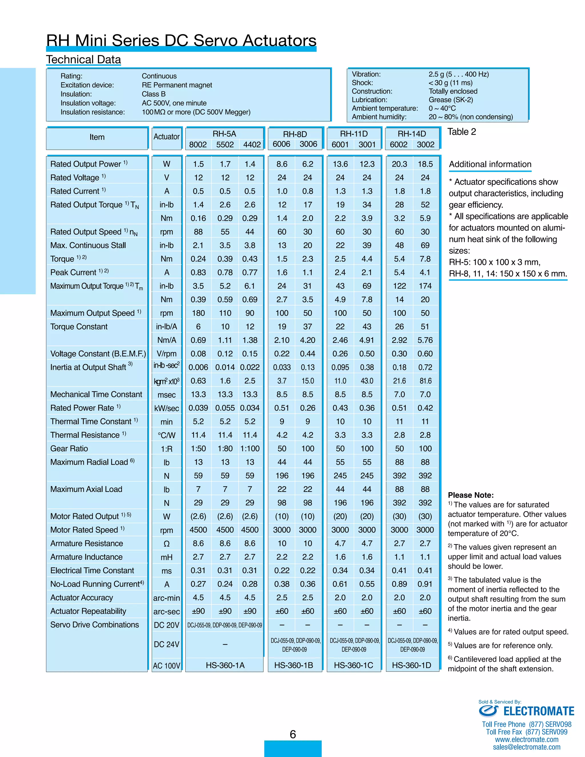
Download to read offline
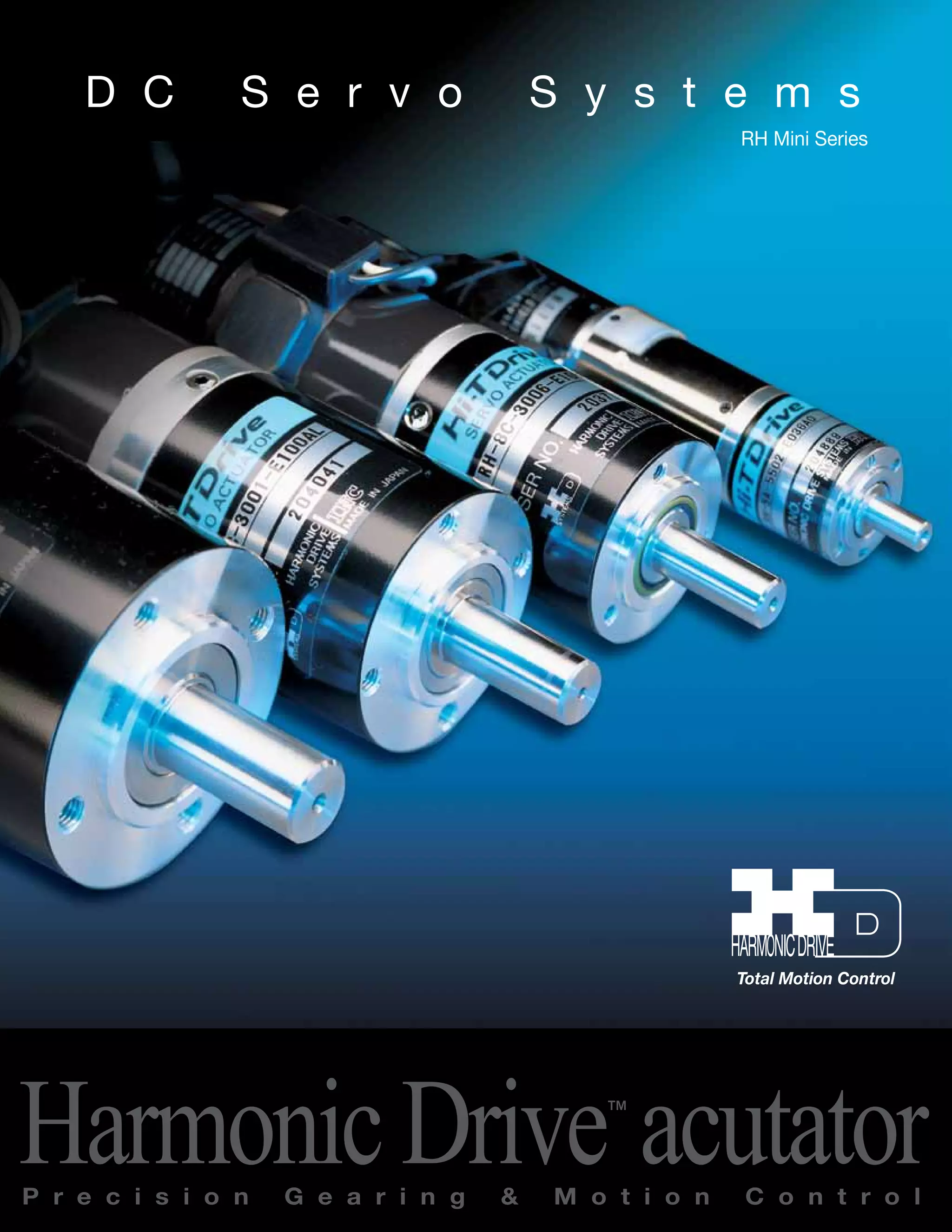
![Determination of the acceleration torque T1 [Nm]
2 π
60
T1 = TL + · (JA + JL) · nL
t1
Acceleration Torque T1 < Maximum Output Torque Tm Select another actuator which
meets this requirement
Requirements for Preliminary Selection
Load Torque TL [Nm] < Rated Torque TN [Nm]
Load Speed nL [rpm] < Rated Output Speed nN [rpm]
Load Inertia JL [kgm2] < 3 JA (Actuator Inertia) acceptable
Load Inertia JL [kgm2] < JA (Actuator Inertia) for best possible
dynamic response
Determination of the duty cycle
Preliminary selection of the actuator
Selected actuator meets all requirements
Select the required encoder resolution
Position Control required Speed Control required
Encoder Resolution
60 · 360
θA · R · γ
n ≥ (5~10) ·
Selection of Encoder Output Type
The most suitable encoder output type can be selected according to the following basic specifications:
◆ AL - Line Driver (+5V version)
This type can transmit the encoder signal up to 10m and requires a 5V DC power supply
◆ BL - Line Driver (+12V version)
This type can transmit the encoder signal up to 100m and requires a 12V DC power supply
◆ DO - Open Collector (+ 4.75V to 12.6V); AO - Open Collector (+5V)
These types can transmit the encoder signal up to 10m. They should not be used in environments suffering
from high levels of electrical noise.
[Equation 1]
Determination of the average torque TA [Nm]
TA = T1
2 · t1 + T2
2 · t2 + T3
2 · t3
with: T1 = Acceleration Torque
T2 = TL = Load Torque
T3 = T2 - (T1 - T2) Braking Torque
t1 + t2 + t3 + t4 ( if t1 = t3 ) [Equation 2]
[Equation 3]
(Values for Tm see page 8, 18, and 19)
No
Average Torque TA < Rated Torque TN of the actuator Select another actuator which
(Values for TN see page 8, 18 and 19) meets this requirement
Where: n = Encoder Resolution
R = Gear reduction ratio
θA = Desired position
accuracy at the output [arc-min]
γ = Encoder multiplier
Encoder Resolution
60 · fs
nmin · R · γ n ≥ 3 ·
Where: nmin = Minimum operating
output speed [rpm]
fs = Cut-off frequency [Hz]
For HS Series Control Units the cut-off fre-quency
fs can be assumed to be 100 Hz.
No
Selection Procedure
[Equation 4]
4
Sold & Serviced By:
ELECTROMATE
Toll Free Phone (877) SERVO98
Toll Free Fax (877) SERV099
www.electromate.com
sales@electromate.com](https://image.slidesharecdn.com/harmonicrhdcservospecsheet-141008202323-conversion-gate02/75/Harmonic-rh-dc_servo_specsheet-4-2048.jpg)
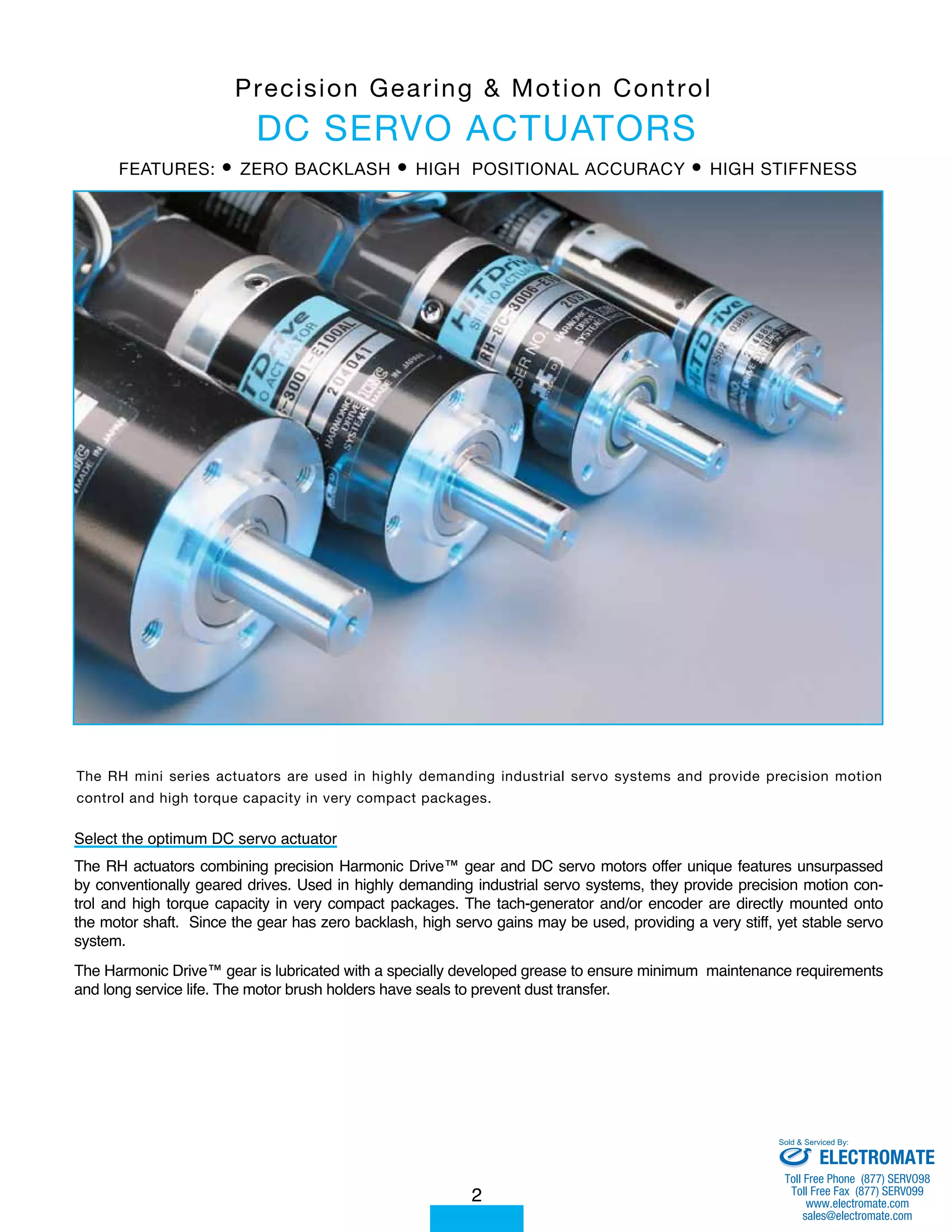
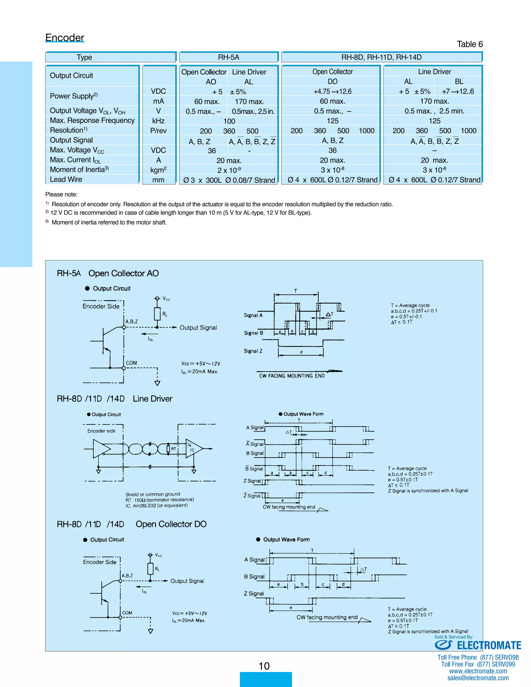
![Performance Curves
7
Torque [Nm]
RH - 8D - 3006
4
2.5
2
1.5
1
0.5
0
10 20 30 40 50 Speed [rpm]
0.25 0.50 0.75 1.00 1.25 Current [A]
3.5
3
CURRENT
SPEED (24V)
RH - 5A - 5502
0.7
0.5
0.4
0.3
0.2
0.1
0
Torque [Nm]
Intermittent
duty zone
20 40 60 80 100 120 Speed [rpm]
0.2 0.4 0.6 0.8 0 2 Current [A]
0.6
SPEED (12V)
CURRENT
Continious
duty zone
RH - 11D - 3001
RH - 14D - 3002
8
7
6
5
4
3
2
20
17.5
12.5
10
7.5
5
0
10 20 30 40 Speed [rpm]
Current [A]
50
1 2 3 4 5
2.5
Torque [Nm]
15
CURRENT
SPEED (24V)
Torque [Nm]
0
10 20 30 40 Speed [rpm]
Current [A]
50
0.5 1.0 1.5 2.0 2.5
1
CURRENT
SPEED (24V)
RH - 14D - 6002
2.5
2
1.5
1
5
4
3
2
12.5
10
7.5
5
2.5
Torque [Nm]
0
25 50 75 100 Speed [rpm]
Current [A]
125
1 2 3 4 5
15
SPEED (24V)
CURRENT
RH - 8D - 6006
50 75 100 0
25 Speed [rpm]
0.5 1.0 1.5 2.0 Current [A]
0.5
Torque [Nm]
3
CURRENT
SPEED (24V)
1
Torque [Nm]
0
25 50 75 100 125
Speed [rpm]
0.5 1.0 1.5 2.0 2.5Current [A]
RH - 11D - 6001
CURRENT
SPEED (24V)
Sold & Serviced By:
ELECTROMATE
Toll Free Phone (877) SERVO98
Toll Free Fax (877) SERV099
www.electromate.com
sales@electromate.com](https://image.slidesharecdn.com/harmonicrhdcservospecsheet-141008202323-conversion-gate02/75/Harmonic-rh-dc_servo_specsheet-7-2048.jpg)
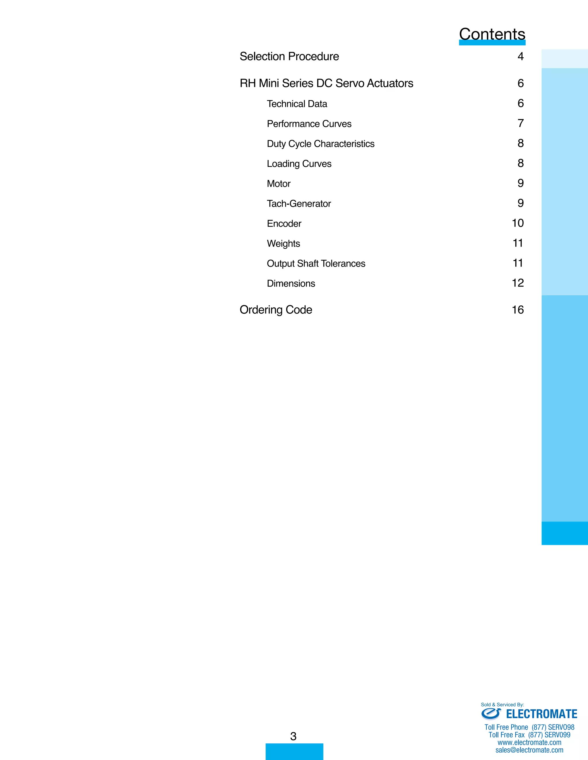
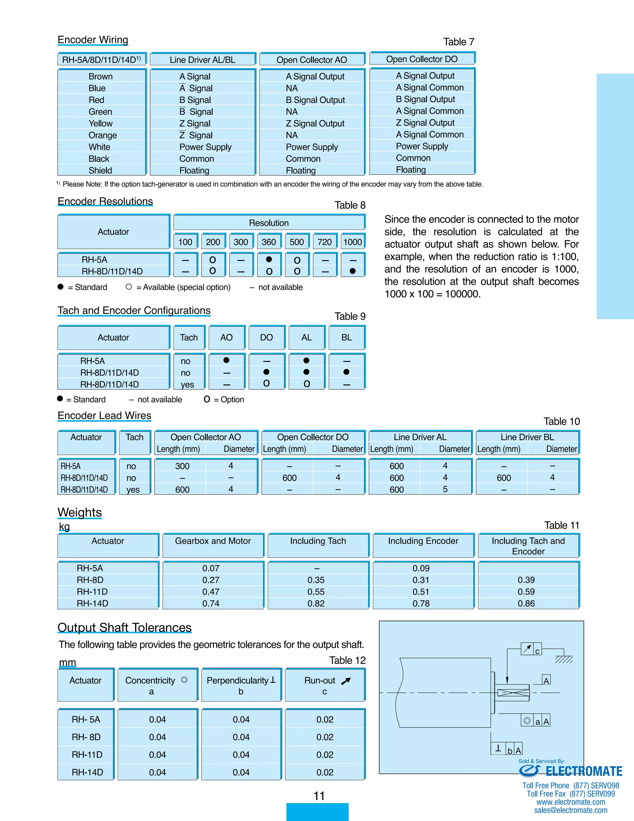
![When an actuator is repeatedly operated above the rated torque and speed for periods of 0.1 minute or more, the
minimum idle time required to prevent damage from overheating can be calculated from the graphs on this page once
the load factor and the duty factor have been established.
8
Calculation example: RH-14D-6002 actuator
For a given load factor of 150% and duty
factor of 30% a permissible operating time
tr = 4 minutes can be read from the curve.
For a duty factor of 30% this means that an
idle time tf = 9.3 minutes is required between
operations.
· 100 %= 30%
tf = - tr = - 4 = 9.3 minutes
Duty Cycle Characteristics
Load factor =
Load torque
Rated torque
tr = operating time
tf = idle time
Loading Curves
· 100 [%]
[Equation 5]
tr
tr + tf
Load factor
tr tf Time t
Duty factor =
(Df) tr
tr + tf
tr
Df
4
.3
· 100 [%]
Please Note:
In the Figs., a segment represented by
a broken line is beyond the maximum
torque of the actuator. This part of the
loading curve should not be used.
Sold & Serviced By:
ELECTROMATE
Toll Free Phone (877) SERVO98
Toll Free Fax (877) SERV099
www.electromate.com
sales@electromate.com](https://image.slidesharecdn.com/harmonicrhdcservospecsheet-141008202323-conversion-gate02/75/Harmonic-rh-dc_servo_specsheet-8-2048.jpg)

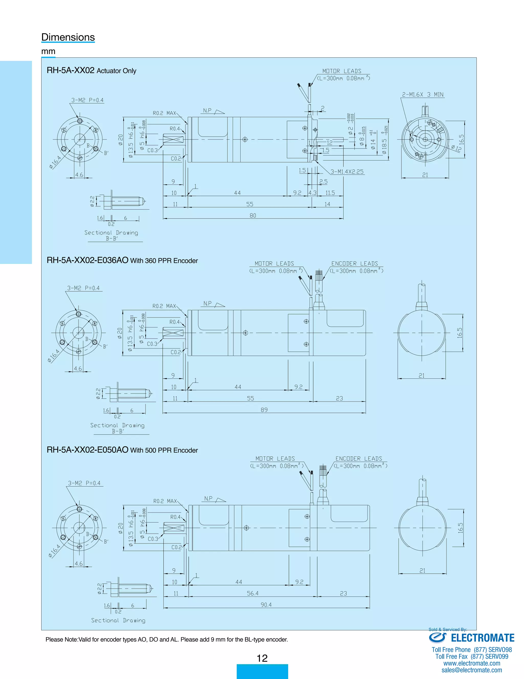
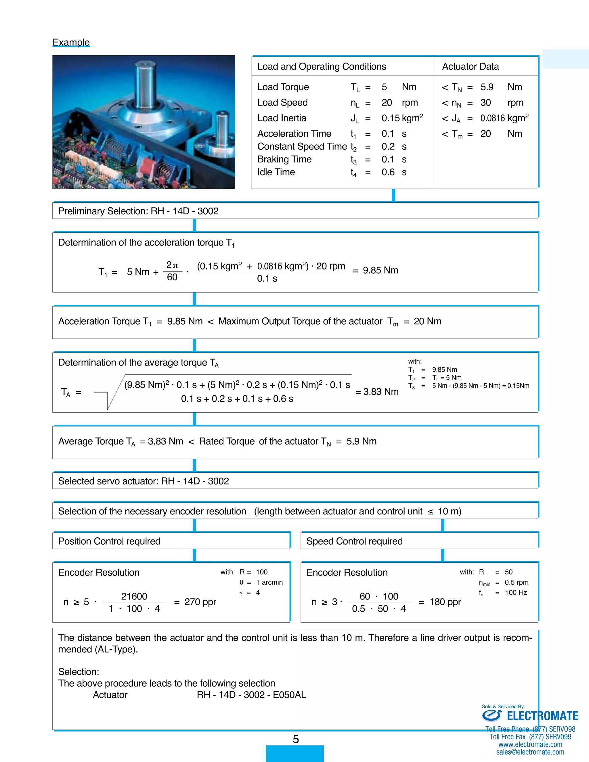
![Ordering Codes
RH - 8D - 6006 - TE050AL - SP
16
Servo Actuators
Series:
RH - with output shaft
Size:
5A, 8D, 11D, 14D
Rated output speed:
60: 60 rpm
30: 30 rpm
For RH-5A/RH-8D: Code represents the
rated output power [W]
For RH-11D/RH-14D: Code represents
one tenth of the rated output power [W]
Encoder (Option) Resolution:
E020 = 200 P/rev
E036 = 360 P/rev
E050 = 500 P/rev
E100 = 1000 P/rev
AL : Line Driver 5V
BL : Line Driver 12V
AO: Open Collector 5V
DO: Open Collector 5 ~ 12V
Specifications
according to
customer
requirements.
Tach-Generator (Option)
: No Tach-Generator Option
T : Tach-Generator Option
(3V / 1000 rpm)
All products are warranted to be free from design or manufacturing defects for a period of one year from the date of
shipment . Such items will be repaired or replaced at the discretion of Harmonic Drive LLC.
The seller makes no warranty , expressed or implied , concerning the material to be furnished other than it shall be of the
quality and specifications stated . The seller ’s liability for any breach is limited to the purchase price of the product .
All efforts have been made to assure that the information in this catalog is complete and accurate . However , Harmonic
Drive LLC is not liable for any errors , ommisions or inaccuracies in the reported data . Harmonic Drive LLC reserves the
right to change the product specifications , for any reason , without prior notice .
Sold Serviced By:
ELECTROMATE
Toll Free Phone (877) SERVO98
Toll Free Fax (877) SERV099
www.electromate.com
sales@electromate.com](https://image.slidesharecdn.com/harmonicrhdcservospecsheet-141008202323-conversion-gate02/75/Harmonic-rh-dc_servo_specsheet-16-2048.jpg)

This document provides specifications for the RH Mini Series DC Servo Actuators from D C Servo Systems. It includes: - Technical data on the torque, speed, power, and dimensions for the RH-5A, RH-8D, RH-11D, and RH-14D actuator models. - Graphs showing the torque and current curves for the RH-8D-3006 and RH-5A-5502 models. - An example selection procedure showing how to select the appropriate actuator model, encoder, and other components based on the load and operating conditions.


