Download to read offline
![International Journal of Engineering Inventions
e-ISSN: 2278-7461, p-ISSN: 2319-6491
Volume 4, Issue 12 [August 2015] PP: 23-30
www.ijeijournal.com Page | 23
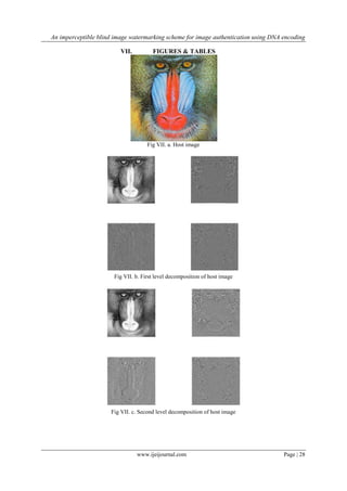
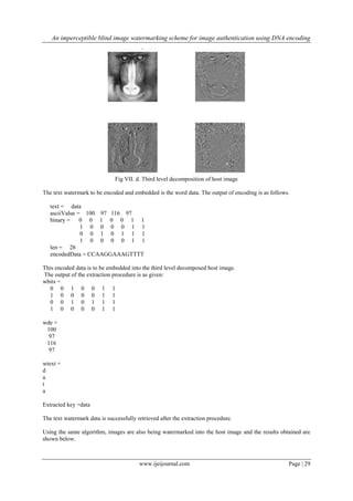
An imperceptible blind image watermarking scheme for image
authentication using DNA encoding and multi-resolution
wavelet decomposition
Pearl Antonette Mendez1
, Rithu James2
1
Mtech student, Dept. of Electronics & Communication, Rajagiri school of engineering & Technology,
Kakkanad, Cochin, Kerala
2
Assistant Professor, Dept. of Electronics & Communication, Rajagiri school of engineering & Technology,
Kakkanad, Cochin, Kerala
Abstract: Digital storage, transmission and manipulation of video signals and still images exhibited a
tremendous growth in the last few years, mainly due to the expansion of computer networks and the introduction
of multimedia technologies to the information market. Copyright protection techniques are in great demand due
to the widespread illegal copying and communication of digital media. One way to protect images against illegal
recordings and retransmissions is to embed a signal, called digital signature or copyright label or watermark,
that completely characterizes the person who applied it and, therefore, marks it as being his intellectual
property. Various watermarking methods have been proposed lately for digital images. Wavelet-based
embedding techniques gained a lot of attention since they provide the perfect balance between imperceptibility
and robustness. In this project, we introduce an algorithm for hiding the complement of a DNA-encoded
watermark data into the 3rd level resolution of the wavelet decomposition of a true colour image. It applies a
quantization operation on the sorted detail coefficients for an enhanced invisible embedding
Keywords: DNA encoding, DWT, Multi-resolution decomposition, wavelets, watermarking
I. INTRODUCTION
The success of the Internet introduces a new set of challenging problems regarding security. One of
many issues that has arisen is the problem of copyright protection of electronic information. Here we address the
problem of watermarking digital image content. For instance, in the case of image data, editing the picture or
illegal tampering should not destroy or transform the watermark into another valid signature. Equally important,
the watermark should not alter the perceived visual quality of the image. From a signal processing perspective,
the two basic requirements for an effective watermarking scheme, robustness and transparency, conflict with
each other.
A digital watermark is intended to complement cryptographic processes. It is a visible, or preferably
invisible, identification code that is permanently embedded in the data and remains present within the data after
any decryption process. [1] A digital watermark is a kind of marker covertly embedded in a noise-tolerant signal
such as audio or image data. It is typically used to identify ownership of the copyright of such signal.
"Watermarking" is the process of hiding digital information in a carrier signal; the hidden information should,
but does not need to, contain a relation to the carrier signal. Digital watermarks may be used to verify the
authenticity or integrity of the carrier signal or to show the identity of its owners. It is prominently used for
tracing copyright infringements and for banknote authentication. Like traditional watermarks, digital
watermarks are only perceptible under certain conditions, i.e. after using some algorithm, and imperceptible
otherwise. If a digital watermark distorts the carrier signal in a way that it becomes perceivable, it is of no use.
Traditional Watermarks may be applied to visible media (like images or video), whereas in digital
watermarking, the signal may be audio, pictures, video, texts or 3D models. A signal may carry several different
watermarks at the same time. Unlike metadata that is added to the carrier signal, a digital watermark does not
change the size of the carrier signal.
Several digital watermarking algorithms have been proposed and these can be categorized according to
their casting/processing domain, signal type of the watermark, and hiding position. Two processing-domain
categories, the spatial-domain and the frequency-domain watermarking, have been proposed. The earlier
watermarking techniques are almost spatial-based approaches; the simplest example is to embed the watermark
in the least significant bits (LSBs) of image pixels[2]. A variety of improvements were proposed against image
compression and filtering. However, these techniques still have relative low-bit capacity and are not resistant
enough to lossy image compression and other image processing.
The needed properties of a digital watermark depend on the use case in which it is applied. For marking media
files with copyright information, a digital watermark has to be rather robust against modifications that can be](https://image.slidesharecdn.com/e04122330-151006104336-lva1-app6891/85/E04122330-1-320.jpg)
![An imperceptible blind image watermarking scheme for image authentication using DNA encoding
www.ijeijournal.com Page | 24
applied to the carrier signal. Instead, if integrity has to be ensured, a fragile watermark would be applied. Both
steganography and digital watermarking employ steganographic techniques to embed data covertly in noisy
signals. But whereas steganography aims for imperceptibility to human senses, digital watermarking tries to
control the robustness as top priority. Since a digital copy of data is the same as the original, digital
watermarking is a passive protection tool. It just marks data, but does not degrade it or control access to the data.
Wavelet-based techniques are gaining popularity since they provide an effective way of imperceptible
embedding while maintaining a high level of robustness against attacks. Another concern is raised regarding the
ability to retrieve the hidden watermark without the need to refer to the original image. The answer to this
question can be used to categorize various techniques into two classes: blind and non-blind schemes. In blind
schemes the embedding process is carried out in such a way that allows the hidden data to be extracted directly
from the watermarked image without knowledge of the original one. On the contrary, in non-blind schemes the
original cover is needed to reveal the hidden information. Obviously, blind techniques are preferred over the
non-blind ones since they are more practical and reliable. [3]
II. DISCRETE WAVELET TRANSFORM
Discrete wavelets transform is a method of signal analysis theory which has arisen in recent years. It is
a frequency domain analysis method which can localize frequency domain and has widely used in many fields.
The basic idea of DWT is the detailed frequency separation of signal, namely multi-resolution decomposition.
The host image is decomposed to four sub-images in size of one quarter: one low frequency approximating
image and three medium and high frequency detail sub-images in horizontal, vertical and diagonal direction.
The high frequency part of discrete wavelets represents the edge, outline and texture information and other
detail information. Embedding watermark is difficult to be detected in these parts, but it is easy to be destroyed
and has a poor stability after image processing. The low frequency part concentrates the most energy of image,
the amplitude of coefficient is larger than the one of detail sub-graph. [4]
Wavelet transform cuts up the data or function into different frequency components to study each
component with resolution matched to its scale due to better frequency and time localization. Wavelets have
become main tool for image processing as process of creating edge sub-images at multiple resolutions are
analogous to a process performed by mammalian vision system including human visual system(HVS). DWT has
a number of advantages over other transforms (DFT or DCT) e.g. progressive and low bit rate transmission,
quality scalability and region of interest (ROI) coding demand more efficient and versatile image. The
decomposition of an image using DWT involves a pair of waveform, one for high frequencies corresponding to
detail part of image (wavelet function(ψ(t) )) and another for low frequencies or smoother part (scaling
function(ϕ(t))). Wavelet function is high pass filter and allows high frequencies components of signal and HVS
is less sensitive to it. It is represented as differences in Haar transform. Scaling function is a low pass filter that
allows low frequencies and sensitive to HVS. It is represented by averages of the data in Haar transform[5].
Fig 1 (a) Layout of the image subbands from the three level dyadic decomposition. (b) An example of
DWT decomposition of the Lena image
The basic idea in the DWT of a 2-D image is as follows. An image is firstly decomposed into four parts of high,
middle, and low frequencies (i.e., LL1, HL1, LH1, HH1) subbands, by cascading horizontal and vertical two-
channel critically sub-sampled filter banks. The sub-bands labeled HL1, LH1,and HH1 represent the finest scale
wavelet coefficients. To obtain the next coarser scale of wavelet coefficients, the subband LL1 is further
decomposed and critically sub-sampled. This process is continued an arbitrary number of times, which is
determined by the application at hand. Each level has various band-information such as low-low, low-high,](https://image.slidesharecdn.com/e04122330-151006104336-lva1-app6891/85/E04122330-2-320.jpg)
![An imperceptible blind image watermarking scheme for image authentication using DNA encoding
www.ijeijournal.com Page | 25
high-low, and high-high frequency bands. Furthermore, from these DWT coefficients, the original image can be
reconstructed. The reconstruction process is called the inverse DWT (IDWT) [6].
III. PROPOSED WATERMARKING ALGORITHM
The hiding process is based on a quantization operation on the detail coefficients of the discrete
wavelet transforms. In an earlier work [7] the robustness of the quantization approach was proved to be efficient
at the 3rd
resolution level of Haar wavelets. Here, we present an additional step concerning the embedded data
[6]. In this step, the watermark data are encoded into DNA alphabets for an added security level. In fact, this
encoding step can be replaced by any recent DNA-based ciphering technique.
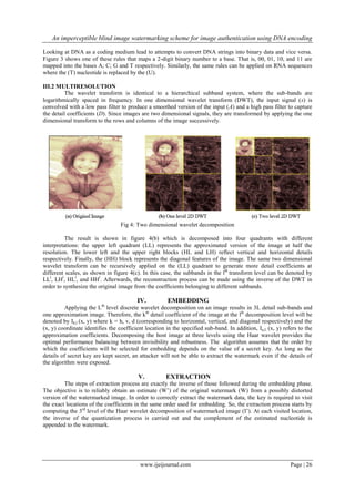
As shown in figure 2, the algorithm proceeds by first encoding the binary watermark into a DNA
sequence. Next, the host image needs to be decomposed into multi-resolution levels using Wavelet (WLT)
transform. The DNA encoded data are then embedded the Wavelet coefficients of the image using some
quantization operation. Finally, the embedded coefficients are inverse transformed resulting in the watermarked
image. On the other side, the extraction process implements the same steps but in reverse order using the same
secret key. Each one of these steps are described in details through the following subsections. We refer to the
original host image as I, the resultant watermarked image as I’, the secret key as Key, and the watermark as W.
The length of the watermark is denoted by Nw.
Fig 2: Proposed watermarking algorithm
III.1 DNA encoding
DNA is a double stranded structure consisting of four types of building blocks or nucleotides: adenine
(A), guanine (G), thymine (T) and cytosine (C). In nature, these bases pair up in a unique complementary way,
where A pairs with T and G pairs with C. Hence, a sequence of DNA base pairs can be viewed as a string made
of these four characters such as AAGTCGATCGATCATCGA. This “genetic code” is read and eventually
translated by the cellular machinery to form proteins in a long and complex process called Central Dogma[13].
The code is read and transcribed from the DNA into messenger RNA (m-RNA) three bases at a time. Each three
adjacent mRNA (C, A, U, G) bases form a single unit known as a codon. This triplet code allows for a total of
64 different codons that are mapped to 20 different amino acids (the building blocks of proteins).
Fig 3: DNA coding of digital data
BITS BASES
00 A
01 C
10 G
11 T](https://image.slidesharecdn.com/e04122330-151006104336-lva1-app6891/85/E04122330-3-320.jpg)
![An imperceptible blind image watermarking scheme for image authentication using DNA encoding
www.ijeijournal.com Page | 30
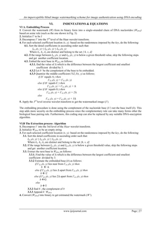
(a) (b)
Fig VII. e (a) Watermark image (b) Watermark retrieved after image decomposition using DWT
(a) (b)
Fig VII. f (a) Second Watermark image (b) Watermark retrieved after image decomposition using DWT
VIII. CONCLUSION
With rapid development of information techniques and network, more and more bugs of traditional
encryption techniques have appeared in digital media copyright protection. An efficient approach for copyright
protection is the digital watermarking technique. In this paper, a blind watermarking technique is being used
since they are more reliable & practical. Here instead of embedding the watermark directly into the host image,
the complement of the watermark is being embedded after encoding it using the DNA encoding technique
making it more difficult for the intruder to retrieve the watermark back increasing the security of the watermark
technique. The watermarks retrieved are legible and hence can be used to prove the ownership of digital data.
REFERENCES
[1]. Ingemar J. Cox, Joe Kilian, F. Thomson Leighton, and Talal Shamoon, “Secure Spread Spectrum
Watermarking for Multimedia”,
[2]. IEEE transactions on image processing, vol. 6, no. 12, DECEMBER 1997, pp 1673-1687
[3]. R. G. van Schyndel, A. Z. Tirkel, and C. F. Osborne, “A digital watermark,” Proc. IEEE Int. Conf. Image
Processing, vol. 2, pp. 86–90, 1994.
[4]. Safwat Hamad & Amal Khalifa, “Robust Blind Image Watermarking using DNA encoding and Discrete
Wavelet Transforms”, 8th
International conference on computer engineering and systems (ICCES),
pp221-227, 2013
[5]. Gursharanjeet Singh Kalra, Dr. Rajneesh Talwar & Dr. Harsh Sadawarti, “Robust Blind Digital Image
Watermarking Using DWT and Dual Encryption Technique”, Third International Conference on
Computational Intelligence, Communication Systems and
Networks, pp 225-230, 2011.
[6]. Gurparkash Singh Kang, “Blind Digital Image Watermarking Using Adpative Casting Energy In
Different Resolutions Of Wavelet
[7]. Transform”, International Conference on Computer & Communication Technology, pp 210-215, 2010.
[8]. Ming-Shing Hsieh, Perceptual copyright protection using multiresolution wavelet based watermarking
and fuzzy logic, “International Journal of Artificial Intelligence & Applications (IJAIA)”, Vol.1, No.3, pp
45-57, July 2010.
[9]. Safwat Hamad, Amal Khalifa, "Quantization-based Image Watermarking using multi-resolution wavelet
decomposition," The Egyptian Computer Science Journal (ECS), vol. 37, no. 3, pp. 26-36, 2013.](https://image.slidesharecdn.com/e04122330-151006104336-lva1-app6891/85/E04122330-8-320.jpg)
This document presents an algorithm for imperceptibly embedding a DNA-encoded watermark into a color image for authentication purposes. It applies a multi-resolution discrete wavelet transform to decompose the image. The watermark, encoded into DNA nucleotides, is then embedded into the third-level wavelet coefficients through a quantization process. Specifically, the watermark nucleotides are complemented and used to quantize coefficients in the middle frequency band, modifying the coefficients. The watermarked image is reconstructed through inverse wavelet transform. Extraction reverses these steps to recover the watermark without the original image. The algorithm aims to balance imperceptibility and robustness through this wavelet-based, blind watermarking scheme.


![[IJET V2I4P2] Authors:Damanbir Singh, Guneet Kaur](https://cdn.slidesharecdn.com/ss_thumbnails/ijet-v2i4p2-160810100856-thumbnail.jpg?width=640&height=640&fit=bounds)

![[IJET-V1I6P5] Authors: Tawde Priyanka, Londhe Archana, Nazirkar Sandhya, Khat...](https://cdn.slidesharecdn.com/ss_thumbnails/ijet-v1i6p5-151213072519-thumbnail.jpg?width=640&height=640&fit=bounds)