Download to read offline
![IOSR Journal of Mechanical and Civil Engineering (IOSR-JMCE)
e-ISSN: 2278-1684,p-ISSN: 2320-334X, Volume 12, Issue 3 Ver. II (May. - Jun. 2015), PP 16-23
www.iosrjournals.org
DOI: 10.9790/1684-12321623 www.iosrjournals.org 16 | Page
Experimental Study and Analysis of Various Machining Process
and Nickel coating on Mild Steel
Mohd Wajid ali1
, Dr.P.Sammaiah2
,N. Sudheer Kumar2
M.Tech Post Graduate Student
Dept. of Mechanical Engineering, SR Engineering College, Warangal, Telangana, India.
2
Professor, Dept. of Mechanical Engineering, SR Engineering College, Warangal, Telangana, India.
2
Asst. Professor. Dept. of Mechanical Engineering, SR Engineering College, Warangal, Telangana, India.
Abstract: Quality of surface is an important factor to decide the performance of a manufactured product.
Surface quality affect product performance like assembly fit, aesthetic appeal that a potential customer might
have for the product. For this study, it has been made of turning, surface Grinding, and Nickel coating process
on Mild steel rod. Developed for external cylindrical & internal cylindrical surface finishing on surface
grinding machine, has been used to test the surface roughness, mechanical properties, Micro structure hardness
test, salt spray testing. The two regimes of rough finishing and fine finishing have been characterized. A sharp
transition from rough to fine finishing occurs at a stone oscillation frequency. The objective of the present work
is to evaluate the parametric study of surface finishing process. An experimental investigation to study the
performance of a surface finishing process by using turning process carbide tool and grinding process abrasive
stones and NI Coated surface finish. The effects of these parameters on surface finish of work-piece have been
investigated.
Keywords: Turning, Cylindrical Grinding, Nickel coating, Speed, Feed, Depth Of Cut, Surface Roughness,
Micro Structure, Hardness Test, Salt Spray.
I. Introduction
Improving the appearance of a finished product for purely aesthetic reasons can be important because it
often increases the salability of the product [1]. The increased product performance and safety provided by
proper edge and surface finishing, hardness, microstructure, corrosion resistance is also important. The removal
of burrs and sharp edges improves safety for both the worker and product user by eliminating the possibility of
cuts and making parts easier to handle [2]. For critical components, the surface condition and edge geometry can
be a major influence on component performance and durability. From strictly an engineering point-of-view,
surface finishing is primarily good for one thing: preventing corrosion. Quality of surface is an important factor
to decide the performance of a manufactured product [3]. Surface quality affect product performance like
assembly fit, aesthetic appeal that a potential customer might have for the product. A surface is defined as the
exterior boundary of an object with its surroundings, which may be any other object, a fluid or space or
combination of these [4]. The surface encloses the object’s bulk mechanical and physical properties. A surface
is what we touch, when we held a manufactured object. Normally dimensions of the object are specified in its
drawing relating the various surfaces to each other. These nominal surfaces, representing the intended surface
contour of the manufactured part, are defined by line in the drawing [5].The nominal surfaces of the object are
represented by perfect straight lines, perfect circles, round holes, absolute perpendicularity and straightness. A
variety of processes are used to make the designed parts. In totality the manufacturing result is wide variations
in surface characteristics [6-7]. It is important to know the technology of surface generation. Only then the root
causes of deviations can be determined and fixed to get the good results.
II. Experimental Details:
2.1 Material Used:
Soft material: MILD STEEL (2062)
Grinding wheel: SiC (GRADE SIZE 60)
DIMENSIONS: L-50mm×70 OD×50 ID
GRADE C% Mn% S% P% Si% C.E%
A 0.23 1.5 0.05 0.05 - 0.42
B 0.22 1.5 0.045 0.045 0.04 0.41
C 0.2 1.5 0.04 0.04 0.4 0.39
Table 1. Compositions at different grades](https://image.slidesharecdn.com/b012321623-160711053130/75/B012321623-1-2048.jpg)
![Experimental Study and Analysis of Various Machining Process and Nickel coating on Mild Steel
DOI: 10.9790/1684-12321623 www.iosrjournals.org 17 | Page
2.2 Experimental Procedure:
A grinding wheel is an expendable wheel used for various grinding and abrasive machining operations.
It is generally made from a matrix of coarse abrasive particles pressed and bonded together to form a solid,
circular shape, various profiles and cross sections are available depending on the intended usage for the wheel.
Grinding wheels may also be made from a solid steel or aluminum disc with particles bonded to the surface.
Figure 1. Cylindrical grinding machine
WHEEL
SPEED
Rpm
WORK
SPEED
Rpm
FEED
mm/Re
v
DOC
Mm
Cutting
speed
m/min
SURFACE
ROUGHNESS
Ra µm
Grain size
Mesh/inch
2500 250 0.15 0.02 549.77 0.248 60
2500 250 0.16 0.02 549.77 0.256 60
2500 250 0.17 0.04 549.77 0.256 60
2500 250 0.11 0.04 549.77 0.238 60
Table 2. Variation of grain size with respect to wheel speed
Turning process: Turning is the removal of metal from the outer diameter of a rotating cylindrical work piece. Turning is
used to reduce the diameter of the work piece, usually to a specified dimension, and to produce a smooth finish on the metal.
Often the work piece will be turned so that adjacent sections have different diameters [8]. The need for selecting and
implementing optimal machining conditions and most suitable cutting tools has been felt very important over few decades.
Surface roughness has become the most significant technical requirement and it is an index of product quality. In order to
develop a surface roughness model and optimize, it is essential to understand the current status of work in this area.
S.No RPM F.R DOC Cutting speed m/min µm RA
1 500 0.10 0.5 109.95 1.67
2 500 0.15 1 109.95 1.94
3 500 0.2 1.5 109.95 2.12
4 800 0.10 0.5 175.92 1.61
5 800 0.15 1 175.92 1.80
6 800 0.2 1.5 175.92 2.25
Table 3 Cutting speed with respect to surface roughness
Surface Methodology can be defined as a statistical method that uses quantitative data from appropriate
experiments to determine the dependent parameters such as, surface roughness, tool life with independent
parameters [9].
Figure 2. Surface roughness tester
Cutting speed, feed rate and depth of cut, in a turning and cylindrical grinding process. The graphical
representations of these equations are called response surfaces, which can be used to describe the individual and](https://image.slidesharecdn.com/b012321623-160711053130/75/B012321623-2-2048.jpg)


![Experimental Study and Analysis of Various Machining Process and Nickel coating on Mild Steel
DOI: 10.9790/1684-12321623 www.iosrjournals.org 23 | Page
Figure No.9 surface finishing process
IV. Conclusions
On the basis of this investigation, the following conclusions can be drawn. .
1. Thus in our project, we have performed a detailed experiment process of the cutting parameters influencing
the surface roughness on a metal after Turning, Grinding, NI coated Process.
2. In our work process we have identified the values of the optimum cutting parameters to get the minimum
Surface roughness.
3. We have experimented with various combinations of the three cutting parameters i.e. Spindle Speed, Depth of
Cut and Feed Rate.
4. We have arrived on a conclusion that the minimum surface roughness in Mild steel is obtained when the
Spindle speed is (2500 rpm approx.), Depth of cut and Feed Rate are minimum (i.e 0.04 mm and 0.11 mm
respectively).
5. The input parameters like speed of grinding, feed, has a significant effect on surface roughness, whereas
depth of cut has the least effect on surface roughness of Mild steel.
6. The optimized minimum surface roughness is 0.238 μm that is about 78% of the initial value.
7. It was found that good surface finish is obtained during the cylindrical grinding process with optimum
grinding conditions.
8. Cutting Speed, Feed Rate and Depth of Cut plays an important role in the cylindrical grinding parameters.
9. The optimum parameters of cylindrical grinding process to overcome the problem of poor surface finishing.
10. Close tolerance can be achieved.
11. Increase in cutting parameters affects the vibration of the grinding machine, grinding wheel, more metal
removal and excessive heat on the work piece. The above causes will results in poor surface finish. This study is
valuable for the Researchers to develop their basic knowledge about fundamental methodology and procedures
are conducted.
12. Analysis is done for the obtained values and it is found that the surface roughness increases with increase in
the depth of cut and with increase in the feed rate.
13. And the surface roughness decrease slightly by increasing the speed. It is found that the feed and depth of
cut is the most affecting factor for surface roughness. Taguchi method has been adopted for the design of
experiments and Optimization of the surface roughness was done using Experimental Tested and Predictive
equation was obtained. A confirmation test was then performed which depicted that the selected parameters and
predictive equation were accurate to within the limits of the measurement instrument.
Acknowledgements
The authors would like to thank them authorities of SR Engineering College‐Warangal, Jyothi Spectro Analysis
Laboratory‐Hyderabad, for providing the facilities to carry out this work.
References
[1]. V. Pallavi, Anoop kumarandT. Mohandas (2012). Optimization of turning parameters for surface roughness using taguchi method.
International Journal of Mechanical Engineering. Vol. 5 : Issue 2.
[2]. Surinder kumar, Meenu and P.S.Satsangi (2012). A genetic algorithmic approach for optimization of surface roughness prediction
model in turning using UD-GFRP composite. Indian Journal of Engineering and Materials Sciences. Vol. 19, 386-396
[3]. S. Thamizhmanii, S. Saparudin, S. Hasan,2007, “Analyses of Surface Roughness by Turning process using Taguchi method”.
Journal of Achievements in Materials and Manufact uring Engineering, Volume 20 Issues 1-2 January-February 2007, pp.503-506.
[4]. 6. Raviraj Shetty, R. Pai, V. Kamathand S. S. Rao, 2008, “Study On Surface Roughness Minimization In Turning Of Dracs Using
Surface Roughness Methodology And Taguchi Under Pressured Steam Jet Approach”. ARPN Journal of Engineering and Applied
Sciences (ISSN: 1819-6608) VOL. 3, NO. 1, February 2008, pp.59-67.
[5]. J. A. Di Bari, “Electrodeposition of nickel,” in Modern Electroplating, M. Schlesinger and M. Paunovic, Eds., John Wiley and Sons,
2000.
[6]. W. Lu, D. Zuo, M. Wang, and F. Xu, “Analysis of interlayer between mild steel and NI ,” Key Engineering Materials, vol. 375-376,
pp. 92–96, 2008. View at Scopus](https://image.slidesharecdn.com/b012321623-160711053130/75/B012321623-8-2048.jpg)

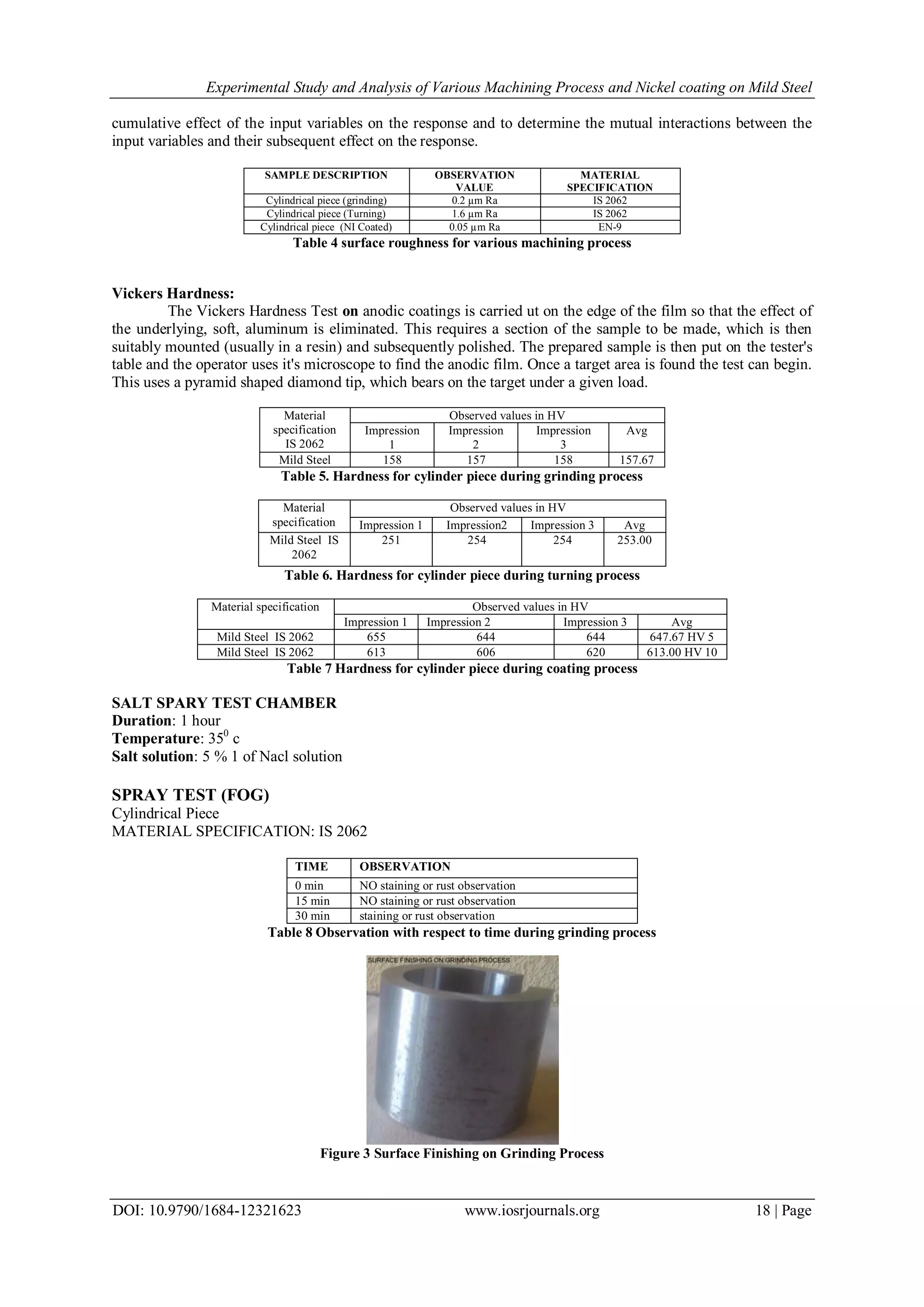
This document presents an experimental study analyzing various machining processes and nickel coating on mild steel. Turning, cylindrical grinding, and nickel coating were performed on mild steel rods. Surface roughness, hardness, microstructure, and corrosion resistance via salt spray testing were evaluated. Turning and grinding were found to produce surface roughness values of 1.6 μm and 0.2 μm respectively. Nickel coating improved surface roughness to 0.05 μm and increased hardness and corrosion resistance. Microstructural analysis found the ground mild steel to consist of 60% ferrite and 40% pearlite grains. The study aims to evaluate these surface finishing processes and analyze the effects of parameters on surface quality.