Download to read offline
![International Journal of Modern Engineering Research (IJMER)
www.ijmer.com Vol.3, Issue.1, Jan-Feb. 2013 pp-139-148 ISSN: 2249-6645
A User-Friendly Image Sharing Scheme Using JPEG-LS
Prediction and LSB Matching Function
Hung P. VO
Department of Engineering and Technology, Tra VinhUniversity, No. 126 National Road 53, Tra Vinh City, Tra Vinh
Province, Viet Nam
Abstract: User-friendly secret sharing encrypts a secret image into n meaningful image shares or shadows first proposed by
Thien and Lin in 2003. Their scheme can achieve the goal of secret image sharing with the additional capabilities of simple
visual-management of shadows owing to representing of shadow images as shrunken version of the original image. After
that, Yang et al. proposed an improved scheme in 2007 by using different primes for various blocks in Shamir’s polynomial
function. In this article, we propose a novel version of (t, n)-threshold user-friendly image sharing scheme which attempts to
indicate prime number for encoding a t-pixel block based on JPEG-LS prediction technique and utilize LSB matching
function to hide indicators of the prime numbers. The simulator presents that the proposed scheme attains the properties of
user-friendly image sharing. In particular, reconstructed image is higher than that of the previous schemes in terms of the
quality of image.
Keywords: image sharing, secret sharing, secret image sharing, user-friendly shadow
I. INTRODUCTION
With the advent of high-speed network infrastructure as well as low-cost computing and networking hardware,
handling and processing digital information by computers and sharing them over internet has become more and more
popular. Since communication via internet is considered insecurely communicated environment, demands for shielding
communicated information is compulsory and necessary. So, security of digital data is an important issue in the design of
communication systems. Data hiding techniques and secret sharing are used to secure confidentiality information while it is
transmitted through unsecured communication channels. Unlike data hiding technique which provides a way of security for
digital image data by embedding secret message in preselected meaningful images, called camouflage images [1-3].
However, the common weak point of them is that secret image is protected in a single information carrier. Once the
carrier is damaged or destroyed, the secret image is lost. Differing from aforementioned methods, secret image sharing
method provides protocol in which a dealer distributes secret data among a set of participants and only the number of the
participants is important for recovering the secret information in the reconstructed phase. This mechanism is not only fault
tolerance, but also fast transmission [6, 7]; such scheme is called a threshold secret sharing scheme.
The concept of secret sharing scheme was introduced in 1979 by Shamir [4], called the (t, n)-threshold scheme.
Shamir’s scheme is based on polynomial interpolation and the polynomial sharing function of degree t1 is defined as
S ( x) s a1 x at 1 x t 1 mod p to encode a secret number s into n shadows (denoted s1, s2, …, sn), where p is the
large prime number selected randomly and coefficients a1, a2, …, at1 are random numbers within [0, p1].
1.1. The shares s1, s2… sn are produced as si= S(xi), for all 1 i n, where x1, x2, …, xn are pair distinct random values.
t
1.2. Given any t pairs ( xi , si )i 1 , the secret s can be derived using Lagrange’s interpolation formula as
t t
x xi
S ( x) ( si ). (1)
i 1 j 1, j i xi x j
In 2002, Thien and Lin [6] extended the secret sharing scheme from number system to image system, and this is
called (t, n)-threshold secret image sharing scheme. In the scheme, coefficients (s, a1… at-1) of the Shamir’s polynomial are
considered as pixel values and the modulus p used in the function is set to 251. A secret image is encoded into n meaningless
shadow images and distributed to n involved participants. The secret image may be only reconstructed without cooperation
of at least a group of t authorized participants. Any number of shadows less than t cannot be used to reveal the secret image.
However, from the view point of security, the system may still expose the secret information to attackers since it is
known that the shares are the noise-like shadow images which may attract malicious user’s attention. To conquer this
shortcoming, recently, many proposed secret image sharing with steganography schemes have been introduced which
construct n pairs of secret shadows. The produced shadows then are embedded into cover images to generate n camouflage
images [8-13]. These camouflage images look like cover images and do not draw attacker’s attention while transmitted to
involved participants via Internet. The constraint of above-mentioned schemes is that the size of cover image is more lager
than that of shadow, so it is commonly not suitable for saved-bandwidth network applications. Besides, although the shadow
images are no longer noise-like but it is still difficult to manage secret image from the view of image management.
Therefore, some recent literature has been devised to overcome the above weaknesses [14, 15]. In 2002, Thien and
Lin [14] proposed an image-sharing mechanism with user-friendly shadow images. Consequently, the generated shadow
images are like the reduction version of the original secret image. In 2007, Yang et al. [15] enhanced and extended the
scheme based on (t1)-degree polynomial functions with different primes in encoding blocks. However, quality of the
reconstructed images is still inferior, making them infeasible for medical, military, or artistic applications [11, 16-17].
www.ijmer.com 139 | Page](https://image.slidesharecdn.com/ax31139148-130314023429-phpapp02/85/Ax31139148-1-320.jpg)
![International Journal of Modern Engineering Research (IJMER)
www.ijmer.com Vol.3, Issue.1, Jan-Feb. 2013 pp-139-148 ISSN: 2249-6645
A User-Friendly Image Sharing Scheme Using JPEG-LS
Prediction and LSB Matching Function
Hung P. VO
Department of Engineering and Technology, Tra VinhUniversity, No. 126 National Road 53, Tra Vinh City, Tra Vinh
Province, Viet Nam
Abstract: User-friendly secret sharing encrypts a secret image into n meaningful image shares or shadows first proposed by
Thien and Lin in 2003. Their scheme can achieve the goal of secret image sharing with the additional capabilities of simple
visual-management of shadows owing to representing of shadow images as shrunken version of the original image. After
that, Yang et al. proposed an improved scheme in 2007 by using different primes for various blocks in Shamir’s polynomial
function. In this article, we propose a novel version of (t, n)-threshold user-friendly image sharing scheme which attempts to
indicate prime number for encoding a t-pixel block based on JPEG-LS prediction technique and utilize LSB matching
function to hide indicators of the prime numbers. The simulator presents that the proposed scheme attains the properties of
user-friendly image sharing. In particular, reconstructed image is higher than that of the previous schemes in terms of the
quality of image.
Keywords: image sharing, secret sharing, secret image sharing, user-friendly shadow
I. INTRODUCTION
With the advent of high-speed network infrastructure as well as low-cost computing and networking hardware,
handling and processing digital information by computers and sharing them over internet has become more and more
popular. Since communication via internet is considered insecurely communicated environment, demands for shielding
communicated information is compulsory and necessary. So, security of digital data is an important issue in the design of
communication systems. Data hiding techniques and secret sharing are used to secure confidentiality information while it is
transmitted through unsecured communication channels. Unlike data hiding technique which provides a way of security for
digital image data by embedding secret message in preselected meaningful images, called camouflage images [1-3].
However, the common weak point of them is that secret image is protected in a single information carrier. Once the
carrier is damaged or destroyed, the secret image is lost. Differing from aforementioned methods, secret image sharing
method provides protocol in which a dealer distributes secret data among a set of participants and only the number of the
participants is important for recovering the secret information in the reconstructed phase. This mechanism is not only fault
tolerance, but also fast transmission [6, 7]; such scheme is called a threshold secret sharing scheme.
The concept of secret sharing scheme was introduced in 1979 by Shamir [4], called the (t, n)-threshold scheme.
Shamir’s scheme is based on polynomial interpolation and the polynomial sharing function of degree t1 is defined as
S ( x) s a1 x at 1 x t 1 mod p to encode a secret number s into n shadows (denoted s1, s2, …, sn), where p is the
large prime number selected randomly and coefficients a1, a2, …, at1 are random numbers within [0, p1].
1.1. The shares s1, s2… sn are produced as si= S(xi), for all 1 i n, where x1, x2, …, xn are pair distinct random values.
t
1.2. Given any t pairs ( xi , si )i 1 , the secret s can be derived using Lagrange’s interpolation formula as
t t
x xi
S ( x) ( si ). (1)
i 1 j 1, j i xi x j
In 2002, Thien and Lin [6] extended the secret sharing scheme from number system to image system, and this is
called (t, n)-threshold secret image sharing scheme. In the scheme, coefficients (s, a1… at-1) of the Shamir’s polynomial are
considered as pixel values and the modulus p used in the function is set to 251. A secret image is encoded into n meaningless
shadow images and distributed to n involved participants. The secret image may be only reconstructed without cooperation
of at least a group of t authorized participants. Any number of shadows less than t cannot be used to reveal the secret image.
However, from the view point of security, the system may still expose the secret information to attackers since it is
known that the shares are the noise-like shadow images which may attract malicious user’s attention. To conquer this
shortcoming, recently, many proposed secret image sharing with steganography schemes have been introduced which
construct n pairs of secret shadows. The produced shadows then are embedded into cover images to generate n camouflage
images [8-13]. These camouflage images look like cover images and do not draw attacker’s attention while transmitted to
involved participants via Internet. The constraint of above-mentioned schemes is that the size of cover image is more lager
than that of shadow, so it is commonly not suitable for saved-bandwidth network applications. Besides, although the shadow
images are no longer noise-like but it is still difficult to manage secret image from the view of image management.
Therefore, some recent literature has been devised to overcome the above weaknesses [14, 15]. In 2002, Thien and
Lin [14] proposed an image-sharing mechanism with user-friendly shadow images. Consequently, the generated shadow
images are like the reduction version of the original secret image. In 2007, Yang et al. [15] enhanced and extended the
scheme based on (t1)-degree polynomial functions with different primes in encoding blocks. However, quality of the
reconstructed images is still inferior, making them infeasible for medical, military, or artistic applications [11, 16-17].
www.ijmer.com 139 | Page](https://image.slidesharecdn.com/ax31139148-130314023429-phpapp02/75/Ax31139148-1-2048.jpg)
![International Journal of Modern Engineering Research (IJMER)
www.ijmer.com Vol.3, Issue.1, Jan-Feb. 2013 pp-139-148 ISSN: 2249-6645
This article presents a novel version of (t, n) user-friendly sharing scheme, capable of producing portrait-looking
shadow images yet still having properties of a secretimage sharing. Particularly, each shadow image contains a slight amount
of information from the original image, in which the contents of the shadow play the identification rather than restore the
original secret image. Herein, the concept of Yang et al.’s image sharing using polynomial with different primes is used to
ensure that each shadow image is a user-friendly share. However, the proposed scheme sets different prime numbers for
encoding different blocks by using the JPEG-LS prediction technique [18-21]. Moreover, to prevent the original image
degradation, LSB matching function [22] is utilized to hide indicators of the prime numbers.
The rest of this paper is organized as follows. Section 2 briefly reviews pertinent literature. Section 3 then describes
the proposed scheme in detail. Section 4 summarizes the experimental results and discussions. Conclusions are finally
drawn in Section 5.
II. RELATED WORKS
In this section, we briefly review the related techniques including the concept of JPEG-LS prediction, using LSB
matching function for hiding indicators of the prime numbers and Yang et al.’s scheme in Subsections 2.1, 2.2 and 2.3,
respectively.
2.1 JPEG-LS Prediction Technique
JPEG-LS technique [18-21] is the latest standard for lossless and near lossless image compression, abbreviated
form of Joint Photographic Experts Group-Lossless Standard. The core algorithm behind JPEG-LS was developed by
Hewlett Packard in 1990s, called Low Complexity Lossless Compression for Images (LOCO-I) [18]. The detailed design of
the algorithm can be summarized in Equation (2) depending on the predictive template shown in Figure 1.
min( A, B) if C max( A, B)
X max( A, B) if C min( A, B) , (2)
A B C otherwise
where min(A,B) and max(A,B) stand for the minimum and maximum values among pixels A and B, respectively.
Figure 1. JPEG-LS predictive template
According to the Equation (2), predicted value X in Figure 1 will be A (B) when there is a vertical (horizontal) edge
detection of the current pixel location X shown in Figure 2; or X will be A + B – C when the neighboring pixels have
comparable values.
Figure 2. Edge detection flowcharts (a) C ≥ max (A,B); (b) C ≤ min(A,B)
2.2 LSB Matching Function for data hiding
Unlike conventional LSB substitution, where secret message is embedded into cover image by replacing the LSBs
of the cover image with message bits, LSB matching [22] does not simply replace the LSBs of the cover image with secret
message bits. In 2009, Chan proposed LSB matching function for data hiding [23]. By adopting a one-dimension approach
instead of two-dimension approach of the image, the LSBs of a sequence of image pixels are computed by XOR function
(XF) defined in Equation (3) to be compatible with the message bits.
www.ijmer.com 140 | Page](https://image.slidesharecdn.com/ax31139148-130314023429-phpapp02/85/Ax31139148-2-320.jpg)
![International Journal of Modern Engineering Research (IJMER)
www.ijmer.com Vol.3, Issue.1, Jan-Feb. 2013 pp-139-148 ISSN: 2249-6645
y (3)
XF ( yi ) LSB i 1 LSB( yi ),
2
Where yi, yi-1 are pixel values at the location i and i1, respectively. The operator is an exclusive OR operator and
LSB (.) is the least-significant-bit function. The LSBs compatible algorithm of sequential pixels with message bits is
presented in Figure 3.
Figure 3. Matching algorithm for pixel and message bit
2.3 Yang et al.’s user-friendly image sharing scheme
In their basic (2, n) user-friendly image sharing using polynomials with different primes [15], the secret image is
first divided into 2-pixel non-overlapping blocks. Then the dealer D choose a set of four primes {p1, p2, p3, p4} satisfied by p1
<p2 <p3 <p4 ≤ 251. In the sharing phase, each block of the secret image is encoded into shadows based on Shamir’s
polynomial function with different prime numbers. The prime number used to encode a block is determined according to the
maximum distance in pixels of block with the last pixel in the previous block. For example, (Pn-2, Pn-1) and (Pn, Pn+1) are the
previous and current two-pixel blocks, respectively. The pixel Pmax leading to the maximum distance from the current block
to the previous block is defined as in (4):
Pn if Pn Pn 1 Pn 1 Pn 1
Pmax . (4)
Pn 1 otherwise
The prime number is then determined according to Pmax . Additionally, the prime number for encoding the block
needs to remember which is used to decode the block in the recovering phase. In each two-pixel block, the LSBs are adjusted
as (00), (01), (10) or (11) to indicate the prime number p1, p2, p3, or p4, respectively, used in decoding the next block. The
LSB of each pixel in the previous block is modified as follows:
LSB( Pn 2 ) 0, LSB( Pn 1 ) 0 for Pmax Pn 1 ( p1 1) / 2
LSB( Pn 2 ) 0, LSB( Pn 1 ) 1 for ( p1 1) / 2 Pmax Pn 1 ( p 2 1) / 2 (5)
LSB( Pn 2 ) 1, LSB( Pn 1 ) 0 for ( p 2 1) / 2 Pmax Pn 1 ( p3 1) / 2
LSB( P ) 1, LSB( P ) 1 for ( p 1) / 2 P P 250
n2 n 1 3 max n 1
Subsequently, Shamir’s polynomial function rewritten as in Equation (6) is applied on the current block.
S ( x) (a0 x a1 ) mod p j for j 1, 2, 3, 4 , (6)
Where the prime number pj is determined by Equation (5), and the coefficients a0 and a1 are computed asfollows:
a0 ( Pn Pn 1 ) ( p j 1) / 2
for j 1, 2, 3 , (7)
a1 ( Pn 1 Pn 1 ) ( p j 1) / 2
a0 ( Pn Pn 1 ) / 2 ( p j 1) / 2
for j 3 . (8)
a1 ( Pn 1 Pn 1 ) / 2 ( p j 1) / 2
www.ijmer.com 141 | Page](https://image.slidesharecdn.com/ax31139148-130314023429-phpapp02/85/Ax31139148-3-320.jpg)
![International Journal of Modern Engineering Research (IJMER)
www.ijmer.com Vol.3, Issue.1, Jan-Feb. 2013 pp-139-148 ISSN: 2249-6645
Finally, shadow pixels ˆ
Pi (1≤ i ≤ n) can be found by locating the value that are closest to the average value of pixels in the
ˆ
current block, but also satisfy the constraint P mod p s .
i j i
The recovering procedure starts by determining the prime number from the previously recovered block and shadow
pixels. Then, using Lagrange interpolation recovers coefficients a0 and a1. After that, the original pixels Pn and Pn+1 are
restored through Equation (7) and (8).
III. PROPOSED SCHEME
Details of the proposed scheme are given in this section. There are two phases: Sharing and retrieving phase.
1.3. Sharing phase
Sharing phase consists of four sub-procedures that may be summarized as in Figure 4. Classification of primes is
the first procedure used to indentify prime number for encoding a block. Indications of primes are embedded in secret image
on using LSB matching function in the second procedure. Modified secret image is partitioned into shadows by sharing
algorithm which is presented in the third procedure. Because Shamir’s secret sharing method is employed, shadows look like
noisy images. Thus, to produce user-friendly share images, an association between the shadow value and the corresponding
average value of block is executed in the fourth procedure.
Figure 4. Flowchart of the sharing phase
1.3.1. Classification of primes procedure
To share an secret image (SI) size of (MN) pixels by using the proposed user-friendly (t, n)-threshold sharing
system with various prime numbers, The dealer D first selects 2t prime numbers (denoted as p1, p2, …, p2 t ) such that
p1 p2 p2t 251 . These prime numbers used in encoding t-pixel non-overlapping blocks are classified according to
the maximum distance of block in pixels. In contrast to scheme in [15], the proposed scheme uses the JPEG-LS prediction
technique [18] to predict value of each pixel depending on the predictive pattern of pixels as in Figure 1 and Equation (2). By
combining the predicted values and the current pixel value, the maximum distance of the m-th block (denoted as d m ) is
defined as in (9):
dm max( Pm X m ) for i 1, 2,, t , (9)
i i
i i i
Where Pm is the pixel value at the position i-th in the m-th block; X m is the predicted value of pixel Pm . Next, the
procedure is continued by indentifying the prime number for block. The criterion to determine prime number for the m-th
block, called pm , is defined as follows:
p1 if d m ( p1 3) / 2,
pm pi if ( pi 1 3) / 2 d m ( pi 3) / 2, and 2 i 2t , (10)
p
2t otherwise.
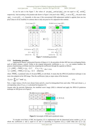
This example demonstrates the procedure, in which a (2, 4)-threshold scheme with four (22) chosen primes {p1, p2, p3, p4} =
{17, 61, 131, 251}. A secret image SI and its predicted values are shown in Figure 5.
www.ijmer.com 142 | Page](https://image.slidesharecdn.com/ax31139148-130314023429-phpapp02/85/Ax31139148-4-320.jpg)
![International Journal of Modern Engineering Research (IJMER)
www.ijmer.com Vol.3, Issue.1, Jan-Feb. 2013 pp-139-148 ISSN: 2249-6645
Figure 5. An example of a secret image SI and its predicted value
According to the Figure 5 and Equation (9), value d m is computed ( d m = max (|160-168|, |161-160|) = 8). Following the
Equation (10), the prime number in encoding m-th block is determined ( pm p2 61) .
1.3.2. Embedding the prime indicators procedure
Since Shamir’s framework is used in the second phase (recovering phase), the prime numbers necessitate to
remember for later use. The prime number is encoded as {(0…00), (0…01)… or (1…11)} to indicate the prime numbers {p1,
p2… or p2 t }. Other word, the indicator id m of prime pm is defined as Equation (11):
t
(0 00) for pm p1
id m (0 01) for pm p2 . (11)
(111) for pm p2t
This procedure would be continued by implementing the embedding indicators of primes into SI based on using
LSB matching function [23], with the result that a matched secret image (MSI) is generated. In that, the LSBs of pixels in
block indicate the prime number which is used in decoding the next block in the recovering phase. In other word, LSBs of
pixels in the previous block of m-th block are compatible with the indicators of the prime number pm.
The matching procedure treat prime indications of block as a sequence bits and consider SI as one-dimensional rather than
two-dimensional array. The flow chart of matching procedure in (t, n)-threshold proposed scheme is shown as in Figure 6.
Figure 6. The flow chart of matching procedure in (t, n)-threshold system
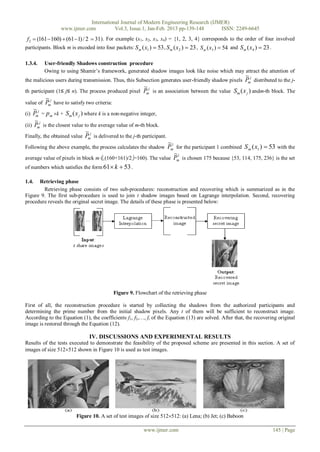
The following example performs the effectiveness of the embedding procedure. As aforementioned, the prime
numbers are longer used in the retrieving phase, the indicators of the prime pm 61 (id m 01) ) are embedded into the SI
using XOR function. The process of embedding procedure is shown in Figure 7. The indicator bits ( id m 0 and id m 1 ) of
1 2
prime p m are matched with the LSBs of two pixels in the previous block of m-th block, respectively.
www.ijmer.com 143 | Page](https://image.slidesharecdn.com/ax31139148-130314023429-phpapp02/85/Ax31139148-5-320.jpg)
![International Journal of Modern Engineering Research (IJMER)
www.ijmer.com Vol.3, Issue.1, Jan-Feb. 2013 pp-139-148 ISSN: 2249-6645
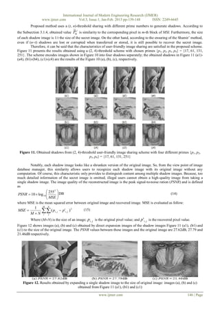
In the revealing phase, proposed scheme uses Lagrange’s interpolation to restore the original image. Any two of
shadow images are gathered, the original image can be reconstructed. Figure 13 (a), (b) and (c) are recovered from any two
shadows of Figure 11 (a1)-(a4), (b1)-(b4) and (c1)-(c4), respectively.
Figure 13. Reconstructed images from any 2 shadow images
During the embedding procedure, in the sharing phase, hides indicators of prime numbers into secret image on
using LSB matching function [23], which is used to limit the modification of the secret image. LSB of each pixel is matched
with the indicator based on XOR function (Equation (3)). Yang et al.’s method uses the conventional LSB replacement
which embeds indicators of primes into secret image by replacing the LSBs of the secret image with indicator bits. Besides,
in the scheme of Yang et al., the determination of prime numbers for a block fully depends on the last pixel of the previous
block. The proposed scheme, by contrast, uses the JPEG-LS prediction technique that estimates accurately predicted pixel
value. The proposed method rarely uses the equation like Equation (8) in Equation (12). Therefore, the proposed method can
obtain better quality of the recovered images. Table 1 presents the image qualities of (2, 4)-threshold of the proposed scheme
compared with those for two previous published user-friendly image sharing method. The values in Table 1 are the PSNR
values of the recovered images. It reveals that the proposed scheme can reconstruct the original image with a higher quality
than that of previous schemes.
Table 1.Qualities of the recovered imagesbased on different user-friendly image-sharing schemes in a set of test images
Proposed
Thien et al. [14] Yang et al. [15]
scheme
Lena 37.37 50.53 52.91
Jet 39.19 49.76 52.90
Baboon 34.75 49.17 52.89
Table 2. Comparison of the proposed scheme with others in terms of the average PSNRs value of expanded shadow images
Proposed
Thien et al. [14] Yang et al. [15]
scheme
Lena 24.80 23.32 27.62
Jet 25.65 23.14 27.79
Baboon 20.55 18.52 21.46
The values shown in the Table 2 are the average PSNRs values of the expanded image and the original image by the
proposed method and other schemes. Notably, the PSNR value of each shadow image is slightly higher than that of the
schemes in [14] and [15]. The moderate quality of shadow images in the proposed scheme is convenient in images
management, rather than recovering a high-quality image based on image-interpolation technique by illegal users.
V. CONCLUSIONS
This paper proposed a novel user-friendly image sharing method with different prime numbers that provides
shadow images among authorized participants. Each participant receives a meaningful image looking like a shrunken version
of the original image. The proposed scheme is based on Yang et al.’s framework. However, in this paper, the prime number
is determined according to the predicted value which leads to the small prime number in encoding block. In addition, the
indicators of prime numbers are embedded into secret image based on the XOR function that limits modification of original
pixel value, so that a better visual quality of the reconstructed image is guaranteed in the proposed scheme.
www.ijmer.com 147 | Page](https://image.slidesharecdn.com/ax31139148-130314023429-phpapp02/85/Ax31139148-9-320.jpg)
![International Journal of Modern Engineering Research (IJMER)
www.ijmer.com Vol.3, Issue.1, Jan-Feb. 2013 pp-139-148 ISSN: 2249-6645
References
[1] W. Bender, D. Gruhl, N. Morimoto and A. Lu, “Techniques for data hiding,” IBM Systems Journal, Vol. 35, pp. 312-336, 1996.
[2] C. T. Hsu and J. L. Wu, “Hiding digital watermarks in images,” IEEE Transactions of Image Processing, Vol. 8, pp. 58-68, 1999.
[3] D. C. Wu and W. H. Tsai, “Data hiding in images via multiple-based number conversion and lossy compression, “IEEE
Transactions on Consumer Electronics Vol. 44, pp. 1406-1412, 1998.
[4] A. Shamir, “How to share a secret,” Communications of the ACM, Vol. 22, no. 11, pp. 612–613, 1979.
[5] G. R. Blakley, “Safeguarding cryptographic keys,” AFIPS 1979 National Computer Conference, Vol. 48, pp. 313–317, 1979.
[6] C. C. Thien, J. C. Lin, “Secret image sharing,” Computers and Graphics, Vol. 26, pp. 765–770, 2002.
[7] S. K. Chen and J. C. Lin, “Fault-tolerant and progressive transmission of images,” Pattern Recognition, Vol. 38, pp. 2466-2471,
2005.
[8] C. C. Lin, W. H. Tsai, “Secret image sharing with steganography and authentication,” Journal of Systems and Software, Vol. 73, pp.
405-414, 2004.
[9] C. N. Yang, T. S. Chen, K. H. Yu, C. C. Wang, “Improvements of image sharing with steganorgraphy and authentication,” Journal
of Systems and Software, Vol. 80, pp. 1070-1076, 2007.
[10] C. C. Chang, Y. P. Hsieh, C. H. Lin, “Sharing secrets in stego images with authentication,” Pattern Recognition, Vol. 41, pp. 3130-
3137, 2008.
[11] P. Y. Lin and C. S. Chan, “Invertible secret image sharing with steganography,” Pattern Recognition Letters, Vol. 31, pp. 1887-
1893, 2010.
[12] Z. Eslami and J. Z. Ahmadabadi, “Secret image sharing with authentication-chaining and dynamic embedding,” Journal of Systems
and Software, Vol. 84, pp. 803-809, 2011.
[13] M. Ulutasa, G. Ulutas and V. V. Nabiyeva, “Medical image security and EPR hiding using Shamir's secret sharing scheme,” Journal
of Systems and Software, Vo. 84, pp. 341-353, 2011.
[14] C. C. Thien and J. C. Lin, “An image-sharing method with user-friendly shadow images,” IEEE Transactions on Circuits and
Systems for Video Technology, Vol. 13, pp. 1161–1169, 2003.
[15] C. N. Yang, K. H. Yu, and R. Lukac, “User-friendly image sharing using polynomials with different primes,” International Journal
of Imaging Systems and Technology Vol. 17, pp. 40–47, 2007.
[16] Zhicheng Ni, Yun Q. Shi, Nirwan Ansari, Wei Su, Qibin, and Xiao Lin, “Robust lossless image data hiding designed for semi-
fragile image authentication,” IEEE Transactions on Circuits and Systems for Video Technology, Vol. 18, pp. 497–509, 2008.
[17] Jun Tian, “Reversible data embedding using a difference expansion,” IEEE Transactions on Circuits and Systems for Video
Technology, Vol. 13, pp.890–896, 2003.
[18] M. Weinberger, G. Seroussi, G. Sapiro, “The LOCO-I Lossless Image Compression Algorithm: Principles and Standardization into
JPEG-LS,” HPL-98-193, 1998.
[19] B. Carpentieri, M. J. Weinberger and G. Seroussi, “Lossless compression of continuous-tone images,” Proceeding of the IEEE, Vol.
88, 2000.
[20] J. Jiang, B. Guo and S. Y. Yang, “Revisiting the JPEG-LS prediction scheme,” IEE Proceedings- Vision, Image and Signal
Processing, Vol. 147, pp. 575-580, 2000.
[21] S. Bedi, E. A. Edirisinghe and G. Grecos, “Improvement to the JPEG-LS prediction scheme,” Journal of Image and Vision
Computing, Vol. 22, pp. 9-14, 2004.
[22] J. Mielikainen, “LSB matching revisited,” IEEE Signal Processing Letters, Vol. 13, pp. 285-287, 2006.
[23] C. S. Chan, “On using LSB matching function for data hiding in pixels,” Fundamenta Informaticae, Vol.96, pp. 49-59, 2009.
www.ijmer.com 148 | Page](https://image.slidesharecdn.com/ax31139148-130314023429-phpapp02/85/Ax31139148-10-320.jpg)

The document summarizes a proposed user-friendly image sharing scheme that uses JPEG-LS prediction and LSB matching functions. The scheme encodes a secret image into meaningful shadow images using different prime numbers for different blocks, as determined by JPEG-LS prediction. It hides the prime number indicators in the least significant bits of pixels using LSB matching to prevent image degradation. The experimental results showed the reconstructed image quality was higher than previous schemes, making it suitable for applications requiring high quality images like medicine, military, or art.