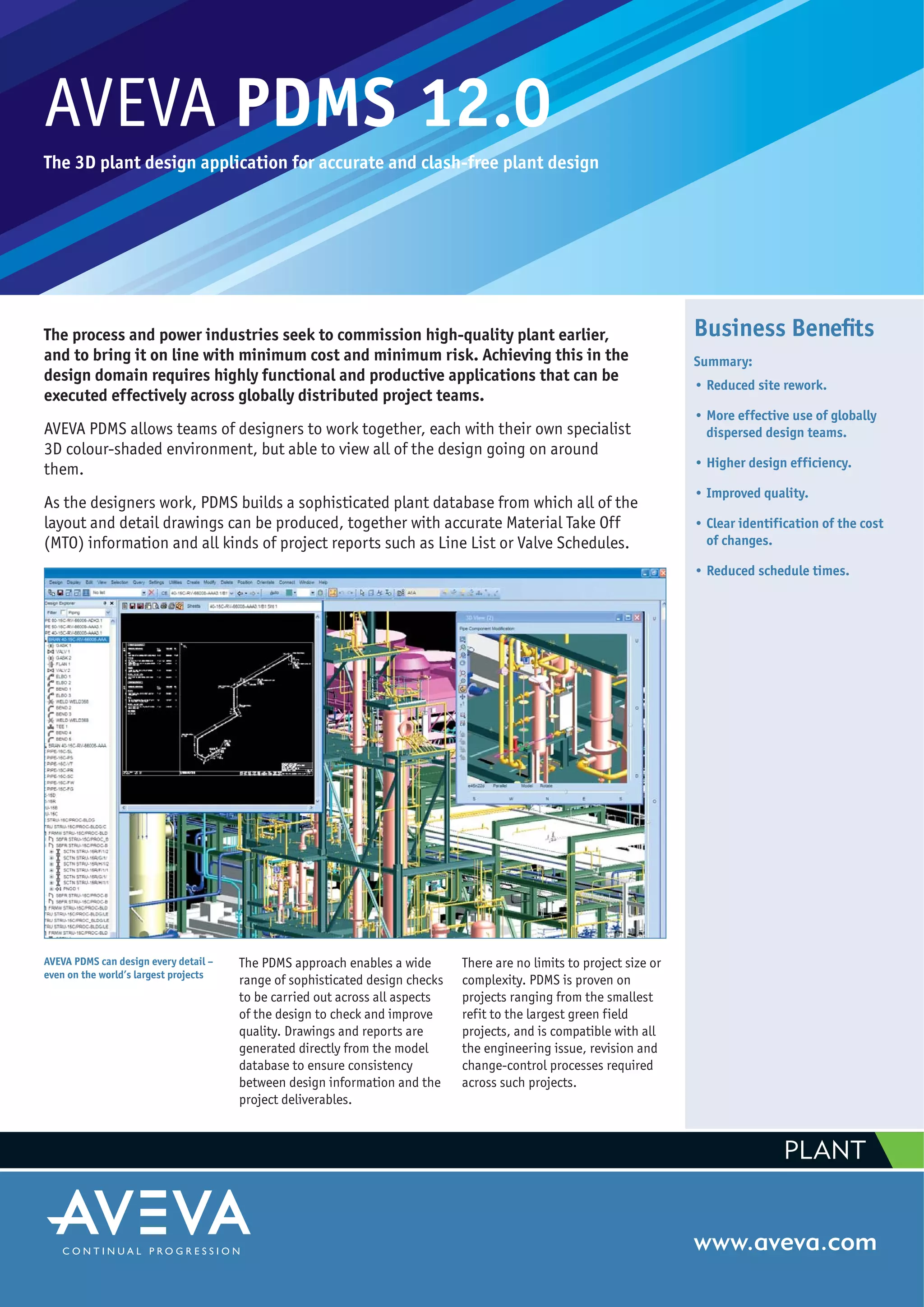
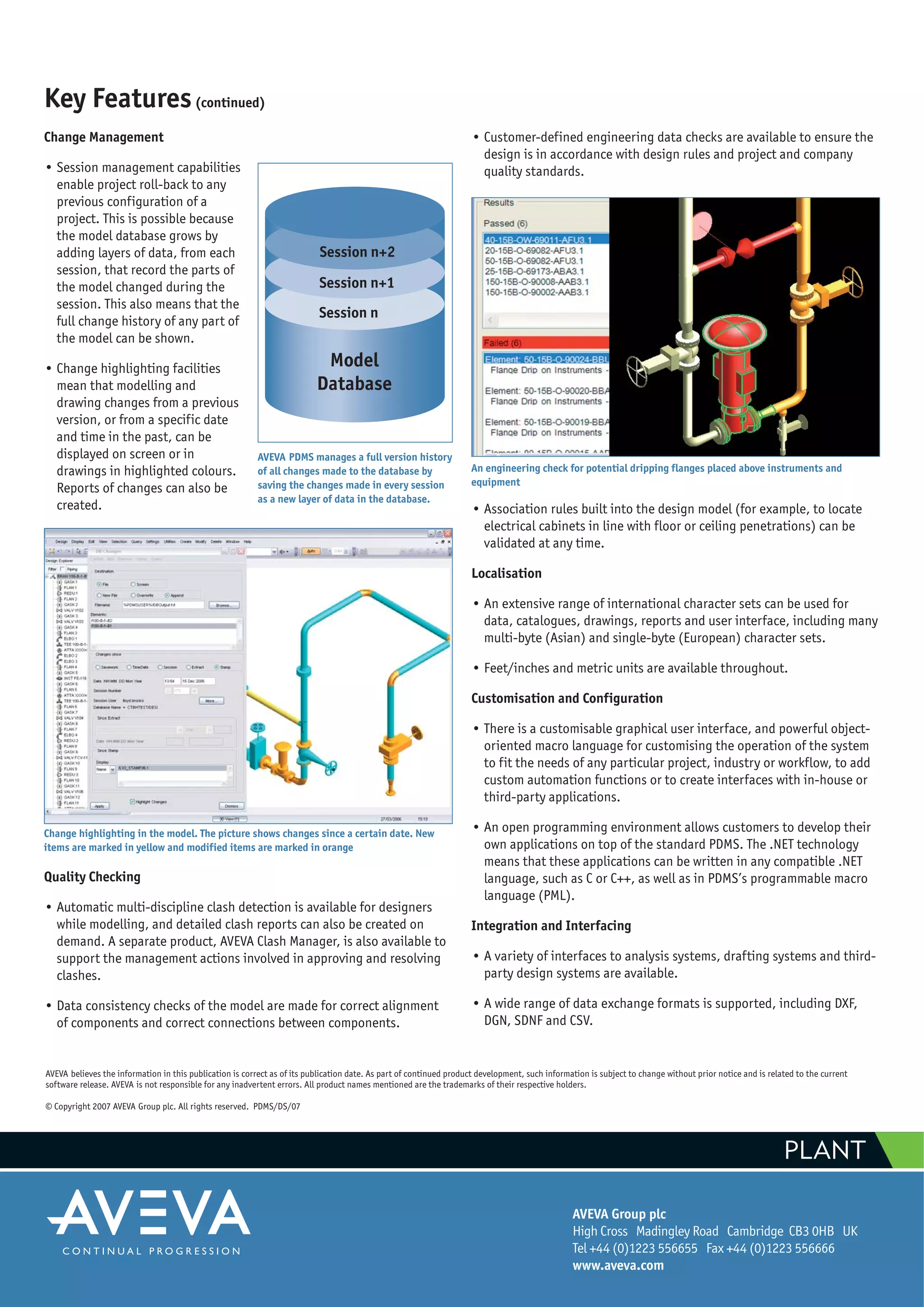
SlideShare a Scribd company logo
AVEVA PDMS 12.0
The 3D plant design application for accurate and clash-free plant design
The process and power industries seek to commission high-quality plant earlier,
and to bring it on line with minimum cost and minimum risk. Achieving this in the
design domain requires highly functional and productive applications that can be
executed effectively across globally distributed project teams.
AVEVA PDMS allows teams of designers to work together, each with their own specialist
3D colour-shaded environment, but able to view all of the design going on around
them.
As the designers work, PDMS builds a sophisticated plant database from which all of the
layout and detail drawings can be produced, together with accurate Material Take Off
(MTO) information and all kinds of project reports such as Line List or Valve Schedules.
www.aveva.com
AVEVA PDMS can design every detail –
even on the world’s largest projects
Business Benefits
Summary:
• Reduced site rework.
• More effective use of globally
dispersed design teams.
• Higher design efficiency.
• Improved quality.
• Clear identification of the cost
of changes.
• Reduced schedule times.
The PDMS approach enables a wide
range of sophisticated design checks
to be carried out across all aspects
of the design to check and improve
quality. Drawings and reports are
generated directly from the model
database to ensure consistency
between design information and the
project deliverables.
There are no limits to project size or
complexity. PDMS is proven on
projects ranging from the smallest
refit to the largest green field
projects, and is compatible with all
the engineering issue, revision and
change-control processes required
across such projects.
PLANT
Key FeaturesBusiness Benefits
Reduced site rework
• Higher quality design. The ability to perform multiple design checks
across the entire design eliminates errors, and enables 'right-first-
time' engineering.
• Accurate materials information eliminates over-ordering and delays
on site due to a lack of required materials or information.
More effective use of globally dispersed design teams
• PDMS, combined with AVEVA Global, allows geographically separate
design teams to work together as though they were in a single
office. The environment delivers high performance for the designer,
centralised administration, control, and protection from
communication limitations or failures.
• Effective use can be made of design capability, wherever it exists.
Project teams can be quickly assembled and mobilised.
Higher design efficiency
• Powerful design applications for each discipline, built upon a highly
visual and interactive 3D environment, with a Microsoft Office-style
user interface, means that designers can become productive very
quickly.
• High levels of automation, intelligent behaviour and rule-based
features deliver increased productivity across all disciplines.
• The ability to share component information and to reuse design
data between projects reduces man-hours and schedule time.
Improved quality
• 3D multi-discipline working environment improves communication
between teams and facilitates 'right-first-time' design.
• Clash checking, integrity checking and rule-based checking tools
ensure higher quality designs and less rework.
• Database-driven drawing production achieves consistency between
drawings, reports and design data.
Clear identification of the cost of changes
• Automatic change highlighting options, both in the design
database and on drawings, make it easier to identify and
communicate change, and to identify the party responsible for any
given change.
• Ability to compare and highlight changes between specific dates,
revisions and milestones.
Reduced schedule times
• Reduced site work, concurrent multi-location engineering, higher
design efficiency and higher quality all combine to reduce schedule
time.
• Greater ability to react quickly to major project changes, including
the capability to change the project structure during project
execution and to dynamically add in new locations or remove
existing ones, all protect the project schedule.
Overview
• PDMS provides a fully interactive, easy-to-use 3D environment for
every designer on the project, supported by a Microsoft Office-style
user interface based on .NET technology and the latest in 3D graphical
interaction tools.
• As the designers work with their specialist functions, they have
visibility of the entire design at all times. To create their part of the
design they place instances of parametric components from a
catalogue (under the control of engineering specifications) and, in
doing so, they construct a highly intelligent PDMS database.
• Clash checking and configurable integrity checking rules identify
errors and inconsistencies across the design.
• Conventional issue, revision, and change control processes can all be
applied without introducing a large overhead or delays in projects
which can have many hundred users.
• State-of-the-art 3D editing features with graphical handles and
numeric feedback make design and modification quick and easy.
Design and Modification is quick and easy – even for the novice user
• Built-in intelligence, combined with configurable rules and
associations, ensure that designers are highly productive during all
design and modification activities.
• Design rules created between plant items (for example, to link a range
of pipes to a penetration or to ensure that a piece of equipment is
correctly located over supporting beams) can be rechecked
automatically at any time during the design.
• Design and component information from earlier PDMS projects can be
reused or shared across multiple projects. Utilities to change pipe size
or specification enable rapid modification to adjust to new project
conditions.
• A general import function from
Microsoft Excel allows large
volumes of data from external
sources to be analysed on line
and bulk-loaded into the design.
• The standard PDMS application
can be customised to fit
individual industry or project
requirements, or to add further
design rules or automation into
the design process.
• Undo and Redo facilities are
widely available. Whole or part
projects can be rewound to any
previous state.
Equipment
• The Equipment functions build 3D models for all kinds of plant items,
from pumps and exchangers through to complex items such as reactor
vessels and compressors. They are used in all kinds of layout studies,
arrangement drawings and connectivity or clash checks.
• Multiple graphical representations are available, so that spaces
required for key maintenance activities can be visualised and clash-
checked during layout and design.
• To create an equipment item in the design, the relevant template is
selected and the required parameters are defined.
• Equipment templates allow complex parameterised design
configurations to be defined so that they can be quickly and easily
reused, even across multiple projects.
• Equipment items include intelligent connection points, with relevant
attributes, for the connection of associated piping, ducting,
instrument and electrical systems.
An example of association rules
A typical AVEVA PDMS Equipment model
An equipment template
Key Features(continued)
Piping
• The Piping functions build a fully detailed model of all piping systems,
based on component catalogues and engineering specifications. From
the piping model, Piping General Arrangement drawings, isometric
drawings and bills of quantity are produced.
• A full range of automatically generated piping isometrics is available,
from complete system isometrics, through to fabrication and erection
isometrics and individual spool isometrics. An enormous number of
options are available to fit any given industry, national, company or
project requirement.
• PDMS manages and integrates all stages of the piping workflow from
initial conceptual routing at the beginning of a project, through basic
and detailed design and on to individual pipe spooling at the
fabricator.
• PDMS piping integrates with AVEVA Multi-Discipline Supports for the
detail design of pipe supports, and with specialist pipe stress
applications, via the AVEVA Pipe Stress Interface. Custom interfaces to
flow calculation systems, wall thickness calculation and other software
can easily be created.
• The Automated pipe routing function allows a preliminary route and
MTO to be created very quickly. The routing includes an automatic
selection of required items such as gaskets and flanges.
• The Quick Pipe Routing function enables the user to define the route of
a pipe by using the mouse pointer to specify changes in direction,
either in absolute terms, or relative to other model features. The route
can be orthogonal or non-orthogonal. Components can be positioned
explicitly or using feature snapping. The route can be completed
automatically where completion is predictable.
• Sophisticated modification capabilities are available at each stage to
allow the piping design to be further developed. These include highly
interactive graphical editing functions, together with functions to
apply specification and pipe bore changes across the line, and to
define and modify slopes.
• Piping Assemblies such as vents, drains or control sets can be added to
the design as an entity. Existing configurations can be saved as
Assemblies and reused elsewhere.
Piping isometrics with full MTO are produced automatically
Regularly used pipe assemblies can be stored and re-used throughout the design
Quick pipe routing
• All drawings, including Piping General Arrangements and isometrics,
have associative dimensions and intelligent annotations, and can
therefore be updated automatically in line with design changes.
• Accurate MTO information can be generated on each sheet or drawing,
or via separate reports for any System, Line, Area, and so on.
• As the design reaches fabrication, the PDMS spooling functionality
manages the creation of individual spool isos, including the creation of
fully intelligent weld items in the model database, which can be
maintained across multiple revision cycles.
• Pipe production checks for bending and flange rotation can be carried
out to check against the actual machines to be used for manufacture,
to ensure that the design easily fits the capabilities of the machines.
Flange rotation checking enables checking that bolt holes in mating
flanges are correctly aligned with each other.
HVAC and Ducting
• PDMS provides a specialist function for the design of all types of
ducting.
• The function uses an engineering specification to select parametric
components from a catalogue allowing a full 3D model to be built.
• A Fill command automatically fills the straight parts of the route with
the appropriate number of straight lengths.
• In-line equipment such as dampers, vanes, diffusers and hoods can all
be included.
• The ducting model can be split into spool parts for manufacture and
pre-assembly and automatic spool and isometric drawings can be
automatically produced.
• PDMS integrates with AVEVA Multi-Discipline Supports for the design of
ducting supports.
Ducting design and spool drawing
Key Features(continued)
Structural and Architectural
• PDMS contains a number of specialist functions for the design and
detailing of steel and concrete structures found in typical process and
power plants. A wide range of layout/arrangement and detail
component drawings can be produced, together with accurate weight
and MTO information.
• The Beams and Columns function defines and maintains a fully
connected nodal network of structural sections including all joint and
fitting details. A simple regular structure can be created in a single
step. The nodal network, coupled with the ability to define loads in the
model, supports integration with analysis software.
• Standard bracing configurations are available and can be customised
as required.
• Curved, tapered and built-up beams are all available.
• The Panels and Plates function defines and maintains flat panels of any
shape.
• The Walls and Floors function
enables designers to define and
maintain walls and floors of
standard shapes.
• Fittings can be added to all types
of beams, plates, walls, floors
and so on, to apply items such as
doors, windows, intelligent
piping penetrations, stiffeners,
lifting lugs and fire-proofing.
• The Access Platforms, Stairs and
Ladders functionality allows
designers to create and
manipulate access platforms,
stairs, stair towers, ladders, and
similar items. The model is built
from a set of customer-definable
parametric standards and
includes all details for each
structure such as handrails and
kick plates. These structures can
be modified later in the design
simply by adjusting the original
parameters.
• Intelligent, parametric penetrations can be defined, together with full
details such as kick plates, and connected to the structure and the
penetrating item (for example, pipe or duct) so that alignment and
other checks can be carried out.
• Structural modelling makes extensive use of parameterised catalogues
for components such as section profiles, joints, and fittings. These
catalogues can be added to by the user to suit particular project or
other requirements.
• Profile catalogues cover the leading international and national profile
standards, including angles, channels and I-beams.
• Joint catalogues contain
standard types of joints
including cleats, end plates and
sniped end preparations. Joint
definitions are parameterised so
that, if a section related to a
joint is resized, the joint can be
resized automatically.
• Fitting catalogues contain a
selection of parameterised
structural and industrial fittings
including lifting lugs, stiffeners,
windows and doors.
• A range of interfacing options is
available to link to specialist
analysis software and specialist
structural fabrication systems.Regular structures can be designed from a single input form
The initial concept level ladder / platform arrangement can be intelligently developed to achieve a completed detail design
A complex joint
Electrical and Instrumentation
• PDMS allows all electrical and instrument items, including electrical
cabinets, transformers and switchgear, to be located in the 3D model
for the purposes of plant layout, visualisation, clash checking and
production of arrangement drawings.
• Electrical and off-line Instrument 3D items can be created from
parameterised templates.
• Valves and in-line instruments are selected from catalogues via
engineering specifications, and the workflow is fully integrated with
piping design, enabling such items to be detailed, for example on
piping isometrics, as required.
• The PDMS cable tray function selects components from a catalogue via
an engineering specification and creates the complete cable tray
layout. A Fill command automatically fills the straight parts of the
route with the appropriate number of straight lengths.
• Cable Tray drawings can be generated for manufacturing purposes.
• PDMS integrates with AVEVA Cable Design for routing electrical and
instrument cables in the design, and integrates with AVEVA Multi-
Discipline Supports for the design of cable tray supports.
Drawings and Reports
• All drawings are produced directly from the PDMS database. The
annotation and dimensions on these drawings are also generated
directly from the database, ensuring high levels of consistency
between documents and design.
• Updates to drawing automatically include the latest design changes.
Automatic change highlighting can be used to clearly show changes
compared to the previous version.
• Drawings are available in AutoCAD- and MicroStation-compatible
formats.
• Layout and other drawings can be finished entirely in PDMS.
Alternatively, they can be transferred to AutoCAD using AVEVA Final
Designer, so that available AutoCAD-skilled labour can be used.
• Flexible reporting capabilities enable all types of reports and schedules
to be produced direct from the PDMS database, such as valve or nozzle
schedules, which can be produced in CSV or other formats.
• Accurate Material Take Off (MTO) information is available across all
disciplines by item, unit, area and so on.
• Reporting options include surface area, weight and centre of gravity.
Catalogues and Specifications
• An extensive set of catalogues covering industry, national and
international standards is available, including piping, structural steel,
ducting, hangers, supports and cable trays.
• Each catalogue provides the parametric definition of all components in
the required size ranges, ratings and types. So, for piping component
connection types, physical and nominal size, material codes and bolt
requirements are all stored.
• Engineering specifications control the way in which components from
the catalogues may be used in the design.
• Standard catalogues can be defined once and shared across multiple
projects.
• New catalogue items, for instance for project specials, can easily be
created by the user.
• Controlled changes to component and specifications are quick and easy
and there are many functions to manage, control and apply such
changes across the design.
Management and Control
• PDMS is designed to support large teams of designers working together
in a controlled and managed way. It has sophisticated and highly
configurable access and change control tools to allow the system to be
tailored for an enormous variety of engineering work practices and
project situations.
• Work breakdown structures can be changed in line with the evolving
project needs, for example, to adapt to changes when construction
contracts are awarded.
• With the use of AVEVA Global, the standard PDMS capabilities can be
extended to manage a PDMS project across geographically separate
locations.
An example of change highlighting in a drawing. The changes since the last revision are
colour coded. Red items are new. Green items have changed annotation. Cyan items are
modified.
Adding or modifying catalogue components is a simple, straightforward activity
AVEVA Group plc
High Cross Madingley Road Cambridge CB3 0HB UK
Tel +44 (0)1223 556655 Fax +44 (0)1223 556666
www.aveva.com
AVEVA believes the information in this publication is correct as of its publication date. As part of continued product development, such information is subject to change without prior notice and is related to the current
software release. AVEVA is not responsible for any inadvertent errors. All product names mentioned are the trademarks of their respective holders.
© Copyright 2007 AVEVA Group plc. All rights reserved. PDMS/DS/07
PLANT
Change Management
• Session management capabilities
enable project roll-back to any
previous configuration of a
project. This is possible because
the model database grows by
adding layers of data, from each
session, that record the parts of
the model changed during the
session. This also means that the
full change history of any part of
the model can be shown.
• Change highlighting facilities
mean that modelling and
drawing changes from a previous
version, or from a specific date
and time in the past, can be
displayed on screen or in
drawings in highlighted colours.
Reports of changes can also be
created.
Quality Checking
• Automatic multi-discipline clash detection is available for designers
while modelling, and detailed clash reports can also be created on
demand. A separate product, AVEVA Clash Manager, is also available to
support the management actions involved in approving and resolving
clashes.
• Data consistency checks of the model are made for correct alignment
of components and correct connections between components.
• Customer-defined engineering data checks are available to ensure the
design is in accordance with design rules and project and company
quality standards.
• Association rules built into the design model (for example, to locate
electrical cabinets in line with floor or ceiling penetrations) can be
validated at any time.
Localisation
• An extensive range of international character sets can be used for
data, catalogues, drawings, reports and user interface, including many
multi-byte (Asian) and single-byte (European) character sets.
• Feet/inches and metric units are available throughout.
Customisation and Configuration
• There is a customisable graphical user interface, and powerful object-
oriented macro language for customising the operation of the system
to fit the needs of any particular project, industry or workflow, to add
custom automation functions or to create interfaces with in-house or
third-party applications.
• An open programming environment allows customers to develop their
own applications on top of the standard PDMS. The .NET technology
means that these applications can be written in any compatible .NET
language, such as C or C++, as well as in PDMS’s programmable macro
language (PML).
Integration and Interfacing
• A variety of interfaces to analysis systems, drafting systems and third-
party design systems are available.
• A wide range of data exchange formats is supported, including DXF,
DGN, SDNF and CSV.
AVEVA PDMS manages a full version history
of all changes made to the database by
saving the changes made in every session
as a new layer of data in the database.
An engineering check for potential dripping flanges placed above instruments and
equipment
Change highlighting in the model. The picture shows changes since a certain date. New
items are marked in yellow and modified items are marked in orange
Key Features(continued)

More Related Content

What's hot

SPI intools Suresh babu
SPI intools Suresh babuSPI intools Suresh babu
SPI intools Suresh babu
SKIETECH INTERNATIONAL RESOURCES
 
Chapter 01 working drawing
Chapter 01 working drawingChapter 01 working drawing
Chapter 01 working drawing
Obuekwec
 
AVEVA Everything 3D
AVEVA Everything 3DAVEVA Everything 3D
AVEVA Everything 3DHadi Karimi
 
Assembly drawing
Assembly drawingAssembly drawing
Assembly drawing
CADmantra Technologies
 
Basic engineering_Checklist
Basic engineering_ChecklistBasic engineering_Checklist
Basic engineering_Checklist
Stephanus Roux C Eng , IntPE(uk) , FIET
 
Introduction to piping design
Introduction to piping designIntroduction to piping design
Introduction to piping design
Ahmad Akileh, PE, PMP
 
Fabrication Drawings
Fabrication DrawingsFabrication Drawings
Fabrication Drawings
Earl Schneider
 
CV_VEERAKAMU.C_PIPING_
CV_VEERAKAMU.C_PIPING_CV_VEERAKAMU.C_PIPING_
CV_VEERAKAMU.C_PIPING_VEERAKAMU C
 
Design Engineer (Mechanical) Valve Design, Manufacturing Industry
Design Engineer (Mechanical) Valve Design, Manufacturing IndustryDesign Engineer (Mechanical) Valve Design, Manufacturing Industry
Design Engineer (Mechanical) Valve Design, Manufacturing Industry
Amarjit Rajeshirke
 
Piping Engineer CV -Sandip Karmakar
Piping Engineer CV -Sandip KarmakarPiping Engineer CV -Sandip Karmakar
Piping Engineer CV -Sandip KarmakarSandip Karmakar
 
Piping basics knowledge
Piping basics knowledgePiping basics knowledge
Piping basics knowledge
ARINDAM BANERJEE
 
Engineering drawing graphics
Engineering drawing graphics Engineering drawing graphics
Engineering drawing graphics
Selva Prakash
 
what is process piping
what is process pipingwhat is process piping
what is process piping
Varun Patel
 
Saurabh Shah Piping Engineer CV
Saurabh Shah Piping Engineer CVSaurabh Shah Piping Engineer CV
Saurabh Shah Piping Engineer CVSaurabh Shah
 
Dimensioning do's and don't
Dimensioning do's and don'tDimensioning do's and don't
Dimensioning do's and don't
Praburam Ganesamoorthy
 
Introduction to Engineering Drawing
Introduction to Engineering Drawing Introduction to Engineering Drawing
Introduction to Engineering Drawing
Chittagoang University of Engineering and Technology
 
Section views
Section viewsSection views
Section views
Shelly Wilke
 

What's hot (20)

PDMS
PDMSPDMS
PDMS
 
Presentation 5-tekla
Presentation 5-teklaPresentation 5-tekla
Presentation 5-tekla
 
SPI intools Suresh babu
SPI intools Suresh babuSPI intools Suresh babu
SPI intools Suresh babu
 
Chapter 01 working drawing
Chapter 01 working drawingChapter 01 working drawing
Chapter 01 working drawing
 
AVEVA Everything 3D
AVEVA Everything 3DAVEVA Everything 3D
AVEVA Everything 3D
 
Assembly drawing
Assembly drawingAssembly drawing
Assembly drawing
 
Basic engineering_Checklist
Basic engineering_ChecklistBasic engineering_Checklist
Basic engineering_Checklist
 
Introduction to piping design
Introduction to piping designIntroduction to piping design
Introduction to piping design
 
Fabrication Drawings
Fabrication DrawingsFabrication Drawings
Fabrication Drawings
 
CV_VEERAKAMU.C_PIPING_
CV_VEERAKAMU.C_PIPING_CV_VEERAKAMU.C_PIPING_
CV_VEERAKAMU.C_PIPING_
 
Design Engineer (Mechanical) Valve Design, Manufacturing Industry
Design Engineer (Mechanical) Valve Design, Manufacturing IndustryDesign Engineer (Mechanical) Valve Design, Manufacturing Industry
Design Engineer (Mechanical) Valve Design, Manufacturing Industry
 
Piping Engineer CV -Sandip Karmakar
Piping Engineer CV -Sandip KarmakarPiping Engineer CV -Sandip Karmakar
Piping Engineer CV -Sandip Karmakar
 
Piping basics knowledge
Piping basics knowledgePiping basics knowledge
Piping basics knowledge
 
Engineering drawing graphics
Engineering drawing graphics Engineering drawing graphics
Engineering drawing graphics
 
what is process piping
what is process pipingwhat is process piping
what is process piping
 
Saurabh Shah Piping Engineer CV
Saurabh Shah Piping Engineer CVSaurabh Shah Piping Engineer CV
Saurabh Shah Piping Engineer CV
 
Dimensioning do's and don't
Dimensioning do's and don'tDimensioning do's and don't
Dimensioning do's and don't
 
Introduction to Engineering Drawing
Introduction to Engineering Drawing Introduction to Engineering Drawing
Introduction to Engineering Drawing
 
Basic piping
Basic pipingBasic piping
Basic piping
 
Section views
Section viewsSection views
Section views
 

Viewers also liked

Pdms latest commands
Pdms latest commandsPdms latest commands
Pdms latest commandsChieu Nguyen
 
Steps to prepare MTO (Material Take Off) in PDMS
Steps to prepare MTO (Material Take Off) in PDMSSteps to prepare MTO (Material Take Off) in PDMS
Steps to prepare MTO (Material Take Off) in PDMS
Aliakbar Nouri
 
Programmable Macro Language (Basic)
Programmable Macro Language (Basic)Programmable Macro Language (Basic)
Programmable Macro Language (Basic)Hadi Karimi
 
AVEVA Diagrams 12.0
AVEVA Diagrams 12.0AVEVA Diagrams 12.0
AVEVA Diagrams 12.0Hadi Karimi
 
How to set ASL (Access, Stair, Ladder) standard for pdms 12 in Module Design ...
How to set ASL (Access, Stair, Ladder) standard for pdms 12 in Module Design ...How to set ASL (Access, Stair, Ladder) standard for pdms 12 in Module Design ...
How to set ASL (Access, Stair, Ladder) standard for pdms 12 in Module Design ...
Aliakbar Nouri
 
Manuales SP3D AUTOMATION TOOLKIT
Manuales SP3D AUTOMATION TOOLKITManuales SP3D AUTOMATION TOOLKIT
Manuales SP3D AUTOMATION TOOLKIT
orv_80
 
Simple Piping design
Simple Piping designSimple Piping design
Simple Piping designMusa Sabri
 

Viewers also liked (10)

AVEVA PDMS TRAINING
AVEVA PDMS TRAININGAVEVA PDMS TRAINING
AVEVA PDMS TRAINING
 
Pdms latest commands
Pdms latest commandsPdms latest commands
Pdms latest commands
 
Steps to prepare MTO (Material Take Off) in PDMS
Steps to prepare MTO (Material Take Off) in PDMSSteps to prepare MTO (Material Take Off) in PDMS
Steps to prepare MTO (Material Take Off) in PDMS
 
Programmable Macro Language (Basic)
Programmable Macro Language (Basic)Programmable Macro Language (Basic)
Programmable Macro Language (Basic)
 
AVEVA Diagrams 12.0
AVEVA Diagrams 12.0AVEVA Diagrams 12.0
AVEVA Diagrams 12.0
 
SCRM[1]
SCRM[1]SCRM[1]
SCRM[1]
 
How to set ASL (Access, Stair, Ladder) standard for pdms 12 in Module Design ...
How to set ASL (Access, Stair, Ladder) standard for pdms 12 in Module Design ...How to set ASL (Access, Stair, Ladder) standard for pdms 12 in Module Design ...
How to set ASL (Access, Stair, Ladder) standard for pdms 12 in Module Design ...
 
Manuales SP3D AUTOMATION TOOLKIT
Manuales SP3D AUTOMATION TOOLKITManuales SP3D AUTOMATION TOOLKIT
Manuales SP3D AUTOMATION TOOLKIT
 
Simple Piping design
Simple Piping designSimple Piping design
Simple Piping design
 
Pdms overview
Pdms overviewPdms overview
Pdms overview
 

Similar to AVEVA PDMS 12.0

AVEVA Multi Discipline Supports
AVEVA Multi Discipline SupportsAVEVA Multi Discipline Supports
AVEVA Multi Discipline SupportsHadi Karimi
 
Field Activity Planner SaaS SW for the Digital Oilfield
Field Activity Planner SaaS SW for the Digital OilfieldField Activity Planner SaaS SW for the Digital Oilfield
Field Activity Planner SaaS SW for the Digital Oilfield
Olav Sylthe
 
AECOsim_Building_Designer_LTR_LoRes_SinglePgs_F_913
AECOsim_Building_Designer_LTR_LoRes_SinglePgs_F_913AECOsim_Building_Designer_LTR_LoRes_SinglePgs_F_913
AECOsim_Building_Designer_LTR_LoRes_SinglePgs_F_913Allwyn Antony
 
AB114-5 BIM-based Collaboration-PPT.pdf
AB114-5 BIM-based Collaboration-PPT.pdfAB114-5 BIM-based Collaboration-PPT.pdf
AB114-5 BIM-based Collaboration-PPT.pdf
RavenousSolos
 
3 dsmart brochure_
3 dsmart brochure_3 dsmart brochure_
3 dsmart brochure_
Rachit Jain
 
Cadison project-engineer
Cadison project-engineerCadison project-engineer
Cadison project-engineerCADISON
 
Cadison project-engineer
Cadison project-engineerCadison project-engineer
Cadison project-engineer
CADISON
 
Project Engineer
Project EngineerProject Engineer
Project Engineer
CADISON
 
Cadison r10
Cadison  r10Cadison  r10
Cadison r10CADISON
 
Cadison R10
Cadison  R10Cadison  R10
Cadison R10
CADISON
 
Intergraph CADWorx & Analysis Flyer
Intergraph CADWorx & Analysis FlyerIntergraph CADWorx & Analysis Flyer
Intergraph CADWorx & Analysis FlyerNicole Brlek
 
Intergraph cad worx_analysis_flyer_2012
Intergraph cad worx_analysis_flyer_2012Intergraph cad worx_analysis_flyer_2012
Intergraph cad worx_analysis_flyer_2012Nicole Brlek
 
CADISON MATPIPE
CADISON MATPIPECADISON MATPIPE
CADISON MATPIPE
CADISON
 
Tecnomatix 11 para Gerencimanento do Processo de Manufatura
Tecnomatix 11 para Gerencimanento do Processo de ManufaturaTecnomatix 11 para Gerencimanento do Processo de Manufatura
Tecnomatix 11 para Gerencimanento do Processo de Manufatura
PLMX -Soluções para Negocios
 
AECOsim_Building_Designer_ProductDataSheet
AECOsim_Building_Designer_ProductDataSheetAECOsim_Building_Designer_ProductDataSheet
AECOsim_Building_Designer_ProductDataSheetAllwyn Antony
 
AVEVA Engineering
AVEVA EngineeringAVEVA Engineering
AVEVA EngineeringHadi Karimi
 

Similar to AVEVA PDMS 12.0 (20)

Aveva pdms (1)
Aveva pdms (1)Aveva pdms (1)
Aveva pdms (1)
 
AVEVA Multi Discipline Supports
AVEVA Multi Discipline SupportsAVEVA Multi Discipline Supports
AVEVA Multi Discipline Supports
 
Field Activity Planner SaaS SW for the Digital Oilfield
Field Activity Planner SaaS SW for the Digital OilfieldField Activity Planner SaaS SW for the Digital Oilfield
Field Activity Planner SaaS SW for the Digital Oilfield
 
AECOsim_Building_Designer_LTR_LoRes_SinglePgs_F_913
AECOsim_Building_Designer_LTR_LoRes_SinglePgs_F_913AECOsim_Building_Designer_LTR_LoRes_SinglePgs_F_913
AECOsim_Building_Designer_LTR_LoRes_SinglePgs_F_913
 
AB114-5 BIM-based Collaboration-PPT.pdf
AB114-5 BIM-based Collaboration-PPT.pdfAB114-5 BIM-based Collaboration-PPT.pdf
AB114-5 BIM-based Collaboration-PPT.pdf
 
3 dsmart brochure_
3 dsmart brochure_3 dsmart brochure_
3 dsmart brochure_
 
Aspen zyqad product_brochure
Aspen zyqad product_brochureAspen zyqad product_brochure
Aspen zyqad product_brochure
 
PDG-PPD-7030
PDG-PPD-7030PDG-PPD-7030
PDG-PPD-7030
 
Cadison project-engineer
Cadison project-engineerCadison project-engineer
Cadison project-engineer
 
Cadison project-engineer
Cadison project-engineerCadison project-engineer
Cadison project-engineer
 
Project Engineer
Project EngineerProject Engineer
Project Engineer
 
Cadison r10
Cadison  r10Cadison  r10
Cadison r10
 
Cadison R10
Cadison  R10Cadison  R10
Cadison R10
 
Intergraph CADWorx & Analysis Flyer
Intergraph CADWorx & Analysis FlyerIntergraph CADWorx & Analysis Flyer
Intergraph CADWorx & Analysis Flyer
 
Intergraph cad worx_analysis_flyer_2012
Intergraph cad worx_analysis_flyer_2012Intergraph cad worx_analysis_flyer_2012
Intergraph cad worx_analysis_flyer_2012
 
CADISON MATPIPE
CADISON MATPIPECADISON MATPIPE
CADISON MATPIPE
 
Tecnomatix 11 para Gerencimanento do Processo de Manufatura
Tecnomatix 11 para Gerencimanento do Processo de ManufaturaTecnomatix 11 para Gerencimanento do Processo de Manufatura
Tecnomatix 11 para Gerencimanento do Processo de Manufatura
 
AECOsim_Building_Designer_ProductDataSheet
AECOsim_Building_Designer_ProductDataSheetAECOsim_Building_Designer_ProductDataSheet
AECOsim_Building_Designer_ProductDataSheet
 
AVEVA Engineering
AVEVA EngineeringAVEVA Engineering
AVEVA Engineering
 
3D Modeling by GIS
3D Modeling by GIS3D Modeling by GIS
3D Modeling by GIS
 

More from Hadi Karimi

Piping Farsi Manual
Piping Farsi ManualPiping Farsi Manual
Piping Farsi ManualHadi Karimi
 
Visual Studio 2008 & .Net 3.5
Visual Studio 2008 & .Net 3.5Visual Studio 2008 & .Net 3.5
Visual Studio 2008 & .Net 3.5Hadi Karimi
 
AVEVA-Schematic-3D-Integrator
AVEVA-Schematic-3D-IntegratorAVEVA-Schematic-3D-Integrator
AVEVA-Schematic-3D-IntegratorHadi Karimi
 
AVEVA Pipe Stress Interface
AVEVA Pipe Stress InterfaceAVEVA Pipe Stress Interface
AVEVA Pipe Stress InterfaceHadi Karimi
 
AVEVA Instrumentation
AVEVA InstrumentationAVEVA Instrumentation
AVEVA InstrumentationHadi Karimi
 
AVEVA Electrical
AVEVA ElectricalAVEVA Electrical
AVEVA ElectricalHadi Karimi
 

More from Hadi Karimi (8)

Piping Farsi Manual
Piping Farsi ManualPiping Farsi Manual
Piping Farsi Manual
 
Visual Studio 2008 & .Net 3.5
Visual Studio 2008 & .Net 3.5Visual Studio 2008 & .Net 3.5
Visual Studio 2008 & .Net 3.5
 
AVEVA-Schematic-3D-Integrator
AVEVA-Schematic-3D-IntegratorAVEVA-Schematic-3D-Integrator
AVEVA-Schematic-3D-Integrator
 
AVEVA Pipe Stress Interface
AVEVA Pipe Stress InterfaceAVEVA Pipe Stress Interface
AVEVA Pipe Stress Interface
 
AVEVA Plant
AVEVA PlantAVEVA Plant
AVEVA Plant
 
AVEVA Review
AVEVA ReviewAVEVA Review
AVEVA Review
 
AVEVA Instrumentation
AVEVA InstrumentationAVEVA Instrumentation
AVEVA Instrumentation
 
AVEVA Electrical
AVEVA ElectricalAVEVA Electrical
AVEVA Electrical
 

AVEVA PDMS 12.0

  • 1. AVEVA PDMS 12.0 The 3D plant design application for accurate and clash-free plant design The process and power industries seek to commission high-quality plant earlier, and to bring it on line with minimum cost and minimum risk. Achieving this in the design domain requires highly functional and productive applications that can be executed effectively across globally distributed project teams. AVEVA PDMS allows teams of designers to work together, each with their own specialist 3D colour-shaded environment, but able to view all of the design going on around them. As the designers work, PDMS builds a sophisticated plant database from which all of the layout and detail drawings can be produced, together with accurate Material Take Off (MTO) information and all kinds of project reports such as Line List or Valve Schedules. www.aveva.com AVEVA PDMS can design every detail – even on the world’s largest projects Business Benefits Summary: • Reduced site rework. • More effective use of globally dispersed design teams. • Higher design efficiency. • Improved quality. • Clear identification of the cost of changes. • Reduced schedule times. The PDMS approach enables a wide range of sophisticated design checks to be carried out across all aspects of the design to check and improve quality. Drawings and reports are generated directly from the model database to ensure consistency between design information and the project deliverables. There are no limits to project size or complexity. PDMS is proven on projects ranging from the smallest refit to the largest green field projects, and is compatible with all the engineering issue, revision and change-control processes required across such projects. PLANT
  • 2. Key FeaturesBusiness Benefits Reduced site rework • Higher quality design. The ability to perform multiple design checks across the entire design eliminates errors, and enables 'right-first- time' engineering. • Accurate materials information eliminates over-ordering and delays on site due to a lack of required materials or information. More effective use of globally dispersed design teams • PDMS, combined with AVEVA Global, allows geographically separate design teams to work together as though they were in a single office. The environment delivers high performance for the designer, centralised administration, control, and protection from communication limitations or failures. • Effective use can be made of design capability, wherever it exists. Project teams can be quickly assembled and mobilised. Higher design efficiency • Powerful design applications for each discipline, built upon a highly visual and interactive 3D environment, with a Microsoft Office-style user interface, means that designers can become productive very quickly. • High levels of automation, intelligent behaviour and rule-based features deliver increased productivity across all disciplines. • The ability to share component information and to reuse design data between projects reduces man-hours and schedule time. Improved quality • 3D multi-discipline working environment improves communication between teams and facilitates 'right-first-time' design. • Clash checking, integrity checking and rule-based checking tools ensure higher quality designs and less rework. • Database-driven drawing production achieves consistency between drawings, reports and design data. Clear identification of the cost of changes • Automatic change highlighting options, both in the design database and on drawings, make it easier to identify and communicate change, and to identify the party responsible for any given change. • Ability to compare and highlight changes between specific dates, revisions and milestones. Reduced schedule times • Reduced site work, concurrent multi-location engineering, higher design efficiency and higher quality all combine to reduce schedule time. • Greater ability to react quickly to major project changes, including the capability to change the project structure during project execution and to dynamically add in new locations or remove existing ones, all protect the project schedule. Overview • PDMS provides a fully interactive, easy-to-use 3D environment for every designer on the project, supported by a Microsoft Office-style user interface based on .NET technology and the latest in 3D graphical interaction tools. • As the designers work with their specialist functions, they have visibility of the entire design at all times. To create their part of the design they place instances of parametric components from a catalogue (under the control of engineering specifications) and, in doing so, they construct a highly intelligent PDMS database. • Clash checking and configurable integrity checking rules identify errors and inconsistencies across the design. • Conventional issue, revision, and change control processes can all be applied without introducing a large overhead or delays in projects which can have many hundred users. • State-of-the-art 3D editing features with graphical handles and numeric feedback make design and modification quick and easy. Design and Modification is quick and easy – even for the novice user
  • 3. • Built-in intelligence, combined with configurable rules and associations, ensure that designers are highly productive during all design and modification activities. • Design rules created between plant items (for example, to link a range of pipes to a penetration or to ensure that a piece of equipment is correctly located over supporting beams) can be rechecked automatically at any time during the design. • Design and component information from earlier PDMS projects can be reused or shared across multiple projects. Utilities to change pipe size or specification enable rapid modification to adjust to new project conditions. • A general import function from Microsoft Excel allows large volumes of data from external sources to be analysed on line and bulk-loaded into the design. • The standard PDMS application can be customised to fit individual industry or project requirements, or to add further design rules or automation into the design process. • Undo and Redo facilities are widely available. Whole or part projects can be rewound to any previous state. Equipment • The Equipment functions build 3D models for all kinds of plant items, from pumps and exchangers through to complex items such as reactor vessels and compressors. They are used in all kinds of layout studies, arrangement drawings and connectivity or clash checks. • Multiple graphical representations are available, so that spaces required for key maintenance activities can be visualised and clash- checked during layout and design. • To create an equipment item in the design, the relevant template is selected and the required parameters are defined. • Equipment templates allow complex parameterised design configurations to be defined so that they can be quickly and easily reused, even across multiple projects. • Equipment items include intelligent connection points, with relevant attributes, for the connection of associated piping, ducting, instrument and electrical systems. An example of association rules A typical AVEVA PDMS Equipment model An equipment template
  • 4. Key Features(continued) Piping • The Piping functions build a fully detailed model of all piping systems, based on component catalogues and engineering specifications. From the piping model, Piping General Arrangement drawings, isometric drawings and bills of quantity are produced. • A full range of automatically generated piping isometrics is available, from complete system isometrics, through to fabrication and erection isometrics and individual spool isometrics. An enormous number of options are available to fit any given industry, national, company or project requirement. • PDMS manages and integrates all stages of the piping workflow from initial conceptual routing at the beginning of a project, through basic and detailed design and on to individual pipe spooling at the fabricator. • PDMS piping integrates with AVEVA Multi-Discipline Supports for the detail design of pipe supports, and with specialist pipe stress applications, via the AVEVA Pipe Stress Interface. Custom interfaces to flow calculation systems, wall thickness calculation and other software can easily be created. • The Automated pipe routing function allows a preliminary route and MTO to be created very quickly. The routing includes an automatic selection of required items such as gaskets and flanges. • The Quick Pipe Routing function enables the user to define the route of a pipe by using the mouse pointer to specify changes in direction, either in absolute terms, or relative to other model features. The route can be orthogonal or non-orthogonal. Components can be positioned explicitly or using feature snapping. The route can be completed automatically where completion is predictable. • Sophisticated modification capabilities are available at each stage to allow the piping design to be further developed. These include highly interactive graphical editing functions, together with functions to apply specification and pipe bore changes across the line, and to define and modify slopes. • Piping Assemblies such as vents, drains or control sets can be added to the design as an entity. Existing configurations can be saved as Assemblies and reused elsewhere. Piping isometrics with full MTO are produced automatically Regularly used pipe assemblies can be stored and re-used throughout the design Quick pipe routing
  • 5. • All drawings, including Piping General Arrangements and isometrics, have associative dimensions and intelligent annotations, and can therefore be updated automatically in line with design changes. • Accurate MTO information can be generated on each sheet or drawing, or via separate reports for any System, Line, Area, and so on. • As the design reaches fabrication, the PDMS spooling functionality manages the creation of individual spool isos, including the creation of fully intelligent weld items in the model database, which can be maintained across multiple revision cycles. • Pipe production checks for bending and flange rotation can be carried out to check against the actual machines to be used for manufacture, to ensure that the design easily fits the capabilities of the machines. Flange rotation checking enables checking that bolt holes in mating flanges are correctly aligned with each other. HVAC and Ducting • PDMS provides a specialist function for the design of all types of ducting. • The function uses an engineering specification to select parametric components from a catalogue allowing a full 3D model to be built. • A Fill command automatically fills the straight parts of the route with the appropriate number of straight lengths. • In-line equipment such as dampers, vanes, diffusers and hoods can all be included. • The ducting model can be split into spool parts for manufacture and pre-assembly and automatic spool and isometric drawings can be automatically produced. • PDMS integrates with AVEVA Multi-Discipline Supports for the design of ducting supports. Ducting design and spool drawing
  • 6. Key Features(continued) Structural and Architectural • PDMS contains a number of specialist functions for the design and detailing of steel and concrete structures found in typical process and power plants. A wide range of layout/arrangement and detail component drawings can be produced, together with accurate weight and MTO information. • The Beams and Columns function defines and maintains a fully connected nodal network of structural sections including all joint and fitting details. A simple regular structure can be created in a single step. The nodal network, coupled with the ability to define loads in the model, supports integration with analysis software. • Standard bracing configurations are available and can be customised as required. • Curved, tapered and built-up beams are all available. • The Panels and Plates function defines and maintains flat panels of any shape. • The Walls and Floors function enables designers to define and maintain walls and floors of standard shapes. • Fittings can be added to all types of beams, plates, walls, floors and so on, to apply items such as doors, windows, intelligent piping penetrations, stiffeners, lifting lugs and fire-proofing. • The Access Platforms, Stairs and Ladders functionality allows designers to create and manipulate access platforms, stairs, stair towers, ladders, and similar items. The model is built from a set of customer-definable parametric standards and includes all details for each structure such as handrails and kick plates. These structures can be modified later in the design simply by adjusting the original parameters. • Intelligent, parametric penetrations can be defined, together with full details such as kick plates, and connected to the structure and the penetrating item (for example, pipe or duct) so that alignment and other checks can be carried out. • Structural modelling makes extensive use of parameterised catalogues for components such as section profiles, joints, and fittings. These catalogues can be added to by the user to suit particular project or other requirements. • Profile catalogues cover the leading international and national profile standards, including angles, channels and I-beams. • Joint catalogues contain standard types of joints including cleats, end plates and sniped end preparations. Joint definitions are parameterised so that, if a section related to a joint is resized, the joint can be resized automatically. • Fitting catalogues contain a selection of parameterised structural and industrial fittings including lifting lugs, stiffeners, windows and doors. • A range of interfacing options is available to link to specialist analysis software and specialist structural fabrication systems.Regular structures can be designed from a single input form The initial concept level ladder / platform arrangement can be intelligently developed to achieve a completed detail design A complex joint
  • 7. Electrical and Instrumentation • PDMS allows all electrical and instrument items, including electrical cabinets, transformers and switchgear, to be located in the 3D model for the purposes of plant layout, visualisation, clash checking and production of arrangement drawings. • Electrical and off-line Instrument 3D items can be created from parameterised templates. • Valves and in-line instruments are selected from catalogues via engineering specifications, and the workflow is fully integrated with piping design, enabling such items to be detailed, for example on piping isometrics, as required. • The PDMS cable tray function selects components from a catalogue via an engineering specification and creates the complete cable tray layout. A Fill command automatically fills the straight parts of the route with the appropriate number of straight lengths. • Cable Tray drawings can be generated for manufacturing purposes. • PDMS integrates with AVEVA Cable Design for routing electrical and instrument cables in the design, and integrates with AVEVA Multi- Discipline Supports for the design of cable tray supports. Drawings and Reports • All drawings are produced directly from the PDMS database. The annotation and dimensions on these drawings are also generated directly from the database, ensuring high levels of consistency between documents and design. • Updates to drawing automatically include the latest design changes. Automatic change highlighting can be used to clearly show changes compared to the previous version. • Drawings are available in AutoCAD- and MicroStation-compatible formats. • Layout and other drawings can be finished entirely in PDMS. Alternatively, they can be transferred to AutoCAD using AVEVA Final Designer, so that available AutoCAD-skilled labour can be used. • Flexible reporting capabilities enable all types of reports and schedules to be produced direct from the PDMS database, such as valve or nozzle schedules, which can be produced in CSV or other formats. • Accurate Material Take Off (MTO) information is available across all disciplines by item, unit, area and so on. • Reporting options include surface area, weight and centre of gravity. Catalogues and Specifications • An extensive set of catalogues covering industry, national and international standards is available, including piping, structural steel, ducting, hangers, supports and cable trays. • Each catalogue provides the parametric definition of all components in the required size ranges, ratings and types. So, for piping component connection types, physical and nominal size, material codes and bolt requirements are all stored. • Engineering specifications control the way in which components from the catalogues may be used in the design. • Standard catalogues can be defined once and shared across multiple projects. • New catalogue items, for instance for project specials, can easily be created by the user. • Controlled changes to component and specifications are quick and easy and there are many functions to manage, control and apply such changes across the design. Management and Control • PDMS is designed to support large teams of designers working together in a controlled and managed way. It has sophisticated and highly configurable access and change control tools to allow the system to be tailored for an enormous variety of engineering work practices and project situations. • Work breakdown structures can be changed in line with the evolving project needs, for example, to adapt to changes when construction contracts are awarded. • With the use of AVEVA Global, the standard PDMS capabilities can be extended to manage a PDMS project across geographically separate locations. An example of change highlighting in a drawing. The changes since the last revision are colour coded. Red items are new. Green items have changed annotation. Cyan items are modified. Adding or modifying catalogue components is a simple, straightforward activity
  • 8. AVEVA Group plc High Cross Madingley Road Cambridge CB3 0HB UK Tel +44 (0)1223 556655 Fax +44 (0)1223 556666 www.aveva.com AVEVA believes the information in this publication is correct as of its publication date. As part of continued product development, such information is subject to change without prior notice and is related to the current software release. AVEVA is not responsible for any inadvertent errors. All product names mentioned are the trademarks of their respective holders. © Copyright 2007 AVEVA Group plc. All rights reserved. PDMS/DS/07 PLANT Change Management • Session management capabilities enable project roll-back to any previous configuration of a project. This is possible because the model database grows by adding layers of data, from each session, that record the parts of the model changed during the session. This also means that the full change history of any part of the model can be shown. • Change highlighting facilities mean that modelling and drawing changes from a previous version, or from a specific date and time in the past, can be displayed on screen or in drawings in highlighted colours. Reports of changes can also be created. Quality Checking • Automatic multi-discipline clash detection is available for designers while modelling, and detailed clash reports can also be created on demand. A separate product, AVEVA Clash Manager, is also available to support the management actions involved in approving and resolving clashes. • Data consistency checks of the model are made for correct alignment of components and correct connections between components. • Customer-defined engineering data checks are available to ensure the design is in accordance with design rules and project and company quality standards. • Association rules built into the design model (for example, to locate electrical cabinets in line with floor or ceiling penetrations) can be validated at any time. Localisation • An extensive range of international character sets can be used for data, catalogues, drawings, reports and user interface, including many multi-byte (Asian) and single-byte (European) character sets. • Feet/inches and metric units are available throughout. Customisation and Configuration • There is a customisable graphical user interface, and powerful object- oriented macro language for customising the operation of the system to fit the needs of any particular project, industry or workflow, to add custom automation functions or to create interfaces with in-house or third-party applications. • An open programming environment allows customers to develop their own applications on top of the standard PDMS. The .NET technology means that these applications can be written in any compatible .NET language, such as C or C++, as well as in PDMS’s programmable macro language (PML). Integration and Interfacing • A variety of interfaces to analysis systems, drafting systems and third- party design systems are available. • A wide range of data exchange formats is supported, including DXF, DGN, SDNF and CSV. AVEVA PDMS manages a full version history of all changes made to the database by saving the changes made in every session as a new layer of data in the database. An engineering check for potential dripping flanges placed above instruments and equipment Change highlighting in the model. The picture shows changes since a certain date. New items are marked in yellow and modified items are marked in orange Key Features(continued)