AVEVA Diagrams 12.0 allows for the easy creation of piping and instrumentation diagrams (P&IDs) and HVAC diagrams that fully integrate with the model database. It provides a fast and efficient solution for creating diagrams. As the diagrams are constructed, design information is created in a schematic model database that can be effectively managed and accessed. The diagrams integrate with the 3D modeling applications AVEVA PDMS and AVEVA Outfitting, allowing consistency between the schematic design and 3D model.
AVEVA World Conference NA - Jesse Trace, AVEVA E3DAVEVA-Americas
Streamline your migration to AVEVA Everything 3D with integrated Structural Design Detailing, using AVEVA Bocad. Improve project execution and enable supply chain teams with to visualize, inspect, comment and approve the fully detailed structure from a mobile tablet device.
The tightly coupled integration between AVEVA Everything3D and AVEVA Bocad Steel gives a best in class plant solution from concept and layout right through to the final fabrication details, producing highly accurate and fast deliverables, with very little need for user intervention, reducing the risk of user error, and leading to increased design efficiency and consistency across projects.
Digital Fabrication Studio.03 _Software @ Aalto Media FactoryMassimo Menichinelli
DIGITAL FABRICATION STUDIO (25438)
The course provides a general understanding on how to design and manufacture products and prototypes in a Fab Lab, using digital fabrication technologies and understanding their features and limits.
Students will learn how information shapes design, manufacturing and collaboration processes and artifacts in a Fab Lab. They will learn how to digitally fabricate a project or how to digitally modify an existing project; students will also learn how to manage, embed and retrieve information about a project. Projects and prototypes developed and manufactured in this course will not be interactive.
The course consists of lectures and a group project to be digitally fabricated, be it a project already designed but not yet realized or be it the modification of an existing project. Every lecture (3 hours) includes time for testing the technologies covered (1 hour) and for developing part of the group project and for receiving feedback about it (1 hour).
http://mlab.taik.fi/studies/courses/course?id=1963
The new revolutionary concept of Building Information Modeling (BIM) is a digital representation of physical and functional characteristics of a facility
Building information modelling (BIM) is a process involving the generation and management of digital representations of physical and functional characteristics of places. Building information models (BIMs) are files (often but not always in proprietary formats and containing proprietary data) which can be extracted, exchanged or networked to support decision-making regarding a building or other built asset.
Contents of the presentation:
1. IFC OVERVIEW
- Back to The Idea of BIM
- Open BIM
- What Is IFC?
- IFC Formats
- IFC Workflow
- Interoperability
- BIM Collaboration Format (BCF)
- Model View Definition (MVD)
- Data Modeling
- Modeling Language
- IFC Data Modeling (Schema)
- EXPRESS Schema
2. IFC DATA MODEL
- Inheritance Hierarchy
- Explicit vs Inverse Attributes
- Objectified Relationships
- Viewers
- Spatial Aggregate Hierarchy
- Geometric Representation Methods
- Relative Positioning
3. ATTRIBUTES & PROPERTIES
- It’s all about Data
- Data Mapping
- Attributes Categories
- Attributes in Revit
- Properties Classification
- IFC Property Sets:
- Revit Implementation
- Data Mapping files
4. IFC: THE NOW & THE FUTURE
- Preview
- Ifc Versions Evolution
- Ifc Certification
- ifcBridge Addition to IFC4.2
- Ifc5.0 Infrastructure & Better GIS Integration
- Ifc New Candidate Formats
- Brief Case Study: Ifcjson Format
The Building Information Modeling (BIM) is a technology that is rapidly gaining popularity in the world of of Architecture Engineering and Construction. This presentation shows a complete history of the BIM and highlights its applications during Building Life Cycle and finally provides its advantages and limitations.
How to set ASL (Access, Stair, Ladder) standard for pdms 12 in Module Design ...Aliakbar Nouri
Many Users could not model ASL in PDMS 12 because of lack of ASL setting.
ASL standard should be specified in ADMIN Module. Attached please find 15 Steps to Set ASL and after that you can find modeling procedure of stair, ladder and platform.
Steps to prepare MTO (Material Take Off) in PDMSAliakbar Nouri
PDMS presents some template for preparation of MTO that highly related to specific naming procedure belongs to PDMS. If any user does not follow mentioned procedure, there will be inaccurate report that caused lots of problem. by following this slide show you can have MTO without considering any specific naming for component in Catalogue module.
Enhance your engineering design process with PTC Creo Illustrate, the leading 3D CAD illustration software. Effortlessly convert CAD data into dynamic 3D animations and interactive illustrations that accurately highlight your product's engineering details. With Creo Illustrate, smoothly communicate complex CAD information, improving collaboration and understanding among teams and stakeholders. Explore the world of 3D technical illustrations and animations with Creo Illustrate today.
The CADISON® P&ID Designer plays a decisive role in design, construction, commissioning and maintenance and has an enormous effect on the complete lifecycle of a plant. In this case the preliminary project engineering will be integrated with Basic and Detail Engineering and 2D layout planning. Apart from the P&I diagrams the P&ID Designer even creates block flow charts and process flow diagrams (PFD).
1. AVEVA Diagrams 12.0
Easy creation of P&ID and HVAC diagrams that fully integrate with the model database
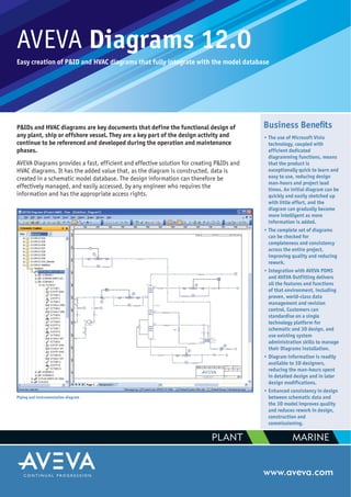
P&IDs and HVAC diagrams are key documents that define the functional design of
any plant, ship or offshore vessel. They are a key part of the design activity and
continue to be referenced and developed during the operation and maintenance
phases.
AVEVA Diagrams provides a fast, efficient and effective solution for creating P&IDs and
HVAC diagrams. It has the added value that, as the diagram is constructed, data is
created in a schematic model database. The design information can therefore be
effectively managed, and easily accessed, by any engineer who requires the
information and has the appropriate access rights.
www.aveva.com
Piping and instrumentation diagram
Business Benefits
• The use of Microsoft Visio
technology, coupled with
efficient dedicated
diagramming functions, means
that the product is
exceptionally quick to learn and
easy to use, reducing design
man-hours and project lead
times. An initial diagram can be
quickly and easily sketched up
with little effort, and the
diagram can gradually become
more intelligent as more
information is added.
• The complete set of diagrams
can be checked for
completeness and consistency
across the entire project,
improving quality and reducing
rework.
• Integration with AVEVA PDMS
and AVEVA Outfitting delivers
all the features and functions
of that environment, including
proven, world-class data
management and revision
control. Customers can
standardise on a single
technology platform for
schematic and 3D design, and
use existing system
administration skills to manage
their Diagrams installation.
• Diagram information is readily
available to 3D designers,
reducing the man-hours spent
in detailed design and in later
design modifications.
• Enhanced consistency in design
between schematic data and
the 3D model improves quality
and reduces rework in design,
construction and
commissioning.
PLANT MARINE
2. Key Features
Easy to use, Visio-based diagramming
• Integrated Microsoft Visio drafting canvas
offers an easy-to-use, feature-rich
environment for drafting P&IDs and HVAC
diagrams.
• Diagrams is available with a set of shapes
called ‘stencils’, which represent some of
the most common diagram symbols used
in shipbuilding and the process plant
industries. This is complemented by an
intuitive import wizard which provides an
easy way to create your own intelligent
stencil shapes. Shapes in stencils can
have default values, as well as the ability
to prompt the user for values when
selected for inclusion in a diagram.
• Diagrams spanning several drawing sheets
using off-page connectors are fully
supported. This mechanism can also be
used for subdividing drawing sheets.
• Diagrams can be made against backdrop
drawings such as general arrangement
drawings.
Integrated with AVEVA PDMS and AVEVA Outfitting
• Items are automatically and instantly created in the model database as
the diagram is being drafted. These items are automatically organised
according to a system hierarchy and a user-defined folder structure.
• The application runs in the same technology environment as the AVEVA
PDMS and AVEVA Outfitting 3D modelling applications, so it has access
to all the database and functional capabilities of that environment.
• The database can store schematic data for all P&IDs in a project. This
means that a complete schematic model of the whole project can be
developed.
• The schematic model created by Diagrams can be used with AVEVA
Schematic 3D Integrator to build the 3D model and to check the
consistency between the P&ID data and the 3D model.
• The item list provides a tabular view of items on the diagram (including
line list, instrument list, valve list and equipment list) which is also
editable in a spreadsheet-style manner.
Different stencil shapes
Inserting a reducer triggers the dimensioning and automatic re-selection of components
AVEVA Schematic
3D Integrator
• Create 3D from P&ID
• Compare P&ID and 3D
• Modify 3D from P&ID
Schematic
Model Data
3D Model
Data
Model Database
AVEVA
Diagrams
P&IDs
HVAC
Diagrams
PDMS or
Outfitting
Pipe/HVAC
Modelling
3. • Instruments created in the diagram are handled as part of the
schematic model and can be managed and reported as other elements
in the database. They can be in line or off line.
• Unique ‘Schematic Model Viewer’ provides automatically generated,
multi-system, navigable presentation of database data.
Specification driven, catalogue-based design capabilities
• Diagrams can be used both with and without piping specifications. This
capability allows a flexible design process so that it is possible, for
instance, to start drawing a diagram without a specification, and then
apply the specification later in the design process.
• Diagrams can work with specifications and catalogues created using
AVEVA PDMS or AVEVA Outfitting.
• In specification-driven mode, the correct components can be
automatically selected as the diagram is created, and existing out-of-
spec items can be rapidly identified and corrected.
• Options for user-controlled selection of components are also available.
• Powerful and easy-to-use resize and respecify functions are available.
These make it quick and easy to modify initial or pre-existing drawings
in line with a rapidly evolving design or a late design change. New
components are automatically associated with the relevant lines and
fittings.
• Automatic exchange of symbols through catalogue definition allows an
initial, ‘generic’ symbol to be replaced by a specific one when the
catalogue reference is set or changed. Existing symbols can also be
manually exchanged, while retaining connections and attributes.
• ‘Fitting assemblies’, provide the ability to define a group of multiple
fittings that can be integrated into the diagram with a single drag-
and-drop operation.
Diagram on a general arrangement backdrop
Off page connectors and annotation
Consistency check for a series of diagrams