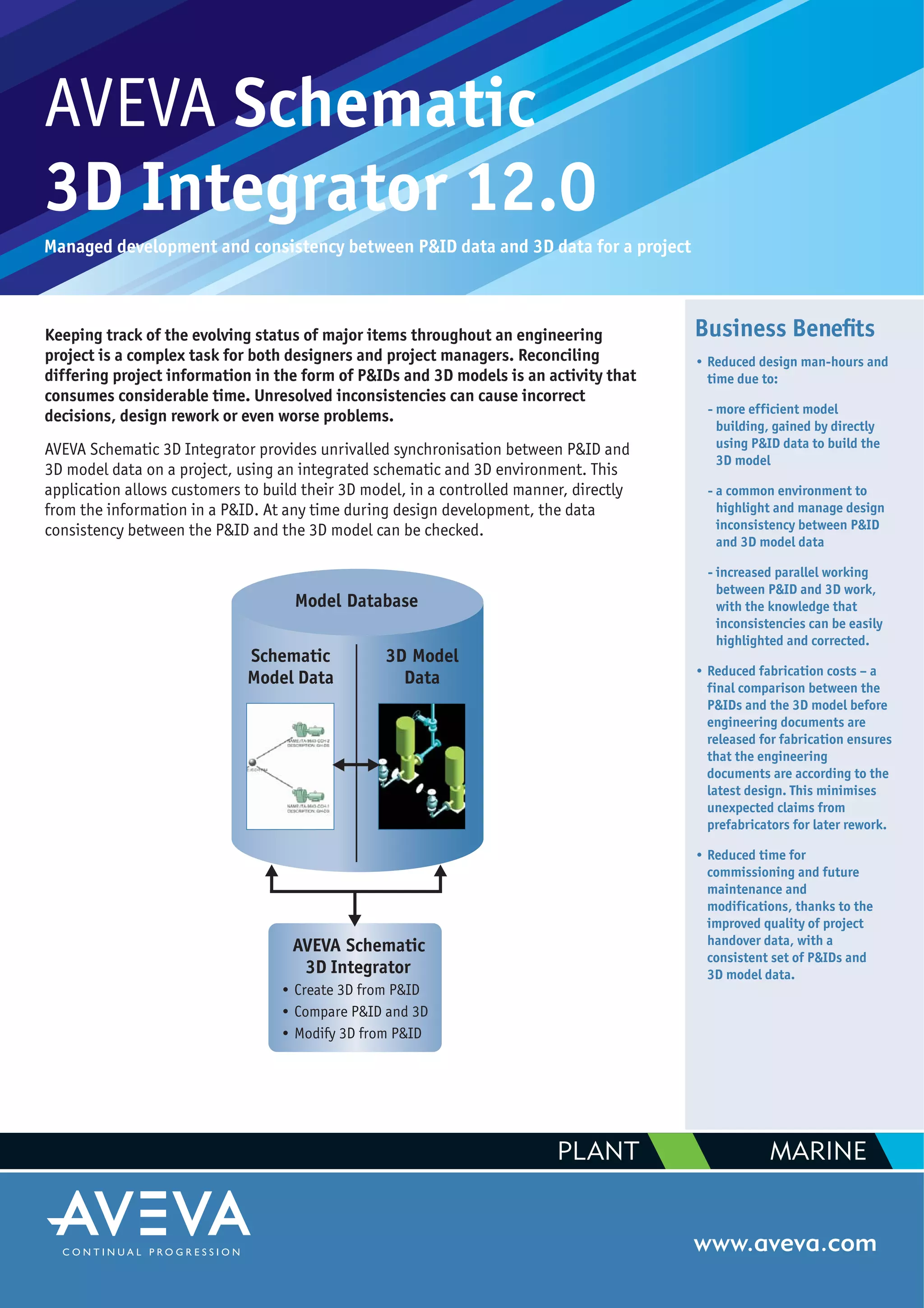
AVEVA Schematic
3D Integrator 12.0
Managed development and consistency between P&ID data and 3D data for a project
www.aveva.com
Keeping track of the evolving status of major items throughout an engineering
project is a complex task for both designers and project managers. Reconciling
differing project information in the form of P&IDs and 3D models is an activity that
consumes considerable time. Unresolved inconsistencies can cause incorrect
decisions, design rework or even worse problems.
AVEVA Schematic 3D Integrator provides unrivalled synchronisation between P&ID and
3D model data on a project, using an integrated schematic and 3D environment. This
application allows customers to build their 3D model, in a controlled manner, directly
from the information in a P&ID. At any time during design development, the data
consistency between the P&ID and the 3D model can be checked.
Business Benefits
• Reduced design man-hours and
time due to:
- more efficient model
building, gained by directly
using P&ID data to build the
3D model
- a common environment to
highlight and manage design
inconsistency between P&ID
and 3D model data
- increased parallel working
between P&ID and 3D work,
with the knowledge that
inconsistencies can be easily
highlighted and corrected.
• Reduced fabrication costs – a
final comparison between the
P&IDs and the 3D model before
engineering documents are
released for fabrication ensures
that the engineering
documents are according to the
latest design. This minimises
unexpected claims from
prefabricators for later rework.
• Reduced time for
commissioning and future
maintenance and
modifications, thanks to the
improved quality of project
handover data, with a
consistent set of P&IDs and
3D model data.
PLANT MARINE
AVEVA Schematic
3D Integrator
• Create 3D from P&ID
• Compare P&ID and 3D
• Modify 3D from P&ID
Schematic
Model Data
3D Model
Data
Model Database
AVEVA Group plc
High Cross Madingley Road Cambridge CB3 0HB UK
Tel +44 (0)1223 556655 Fax +44 (0)1223 556666
www.aveva.com
AVEVA believes the information in this publication is correct as of its publication date. As part of continued product development, such information is subject to change without prior notice and is related to the current
software release. AVEVA is not responsible for any inadvertent errors. All product names mentioned are the trademarks of their respective holders.
© Copyright 2009 AVEVA Group plc. All rights reserved. S3DI/DS/09
Key Features
• Schematic 3D Integrator runs in the same technology environment as
the AVEVA 3D modelling applications, so it has access to all the
database and functional capabilities of that environment.
• The model database can store schematic data for all P&IDs in a project.
This means that a complete schematic model of the whole project can
be developed – even if multiple P&ID authoring tools have been used
on the project.
• The schematic model data can be used to build the related 3D objects
such as equipment and pipes. First, the P&ID designer must release his
P&ID parts for 3D modelling. The Schematic 3D Integrator can identify
P&ID parts released but not yet associated with 3D. In the case of
pipes, all branches and inline fittings such as valves and reducers, as
well as instruments, are handled. The application will build the 3D
model for these elements. Rules may be provided by the user to
automatically set a location in 3D space and other attributes. It is then
possible to use the normal model editing tools to fine-tune the
location of the model parts.
• When the Build function is used, an association is created between the
P&ID part and the relevant 3D model part. However, in some cases, the
3D model may already exist, or the P&ID and the 3D model are
developed in parallel. In such a case, the application can be used to
manually associate a P&ID part with a 3D model part, so that
consistency checks can be made later.
• To ensure consistency between the schematic data and the 3D model, a
powerful Compare function is available to check the associated parts.
Comparisons are of two types:
- structural comparison, where the hierarchy and connections of the
design data are checked
- attribute comparison, where key attributes and references are
checked.
In the event of mismatching values, there is an option to change
incorrect 3D model values.
• Comparison results are shown in text-style reports and via colour-
coding of the schematic and 3D views on the screen. The default
setting for the user-definable colour-coding is:
- green: no inconsistencies
- yellow: warning
- red: error
- blue: unresolved
PLANT MARINE
AVEVA Schematic 3D Integrator user interface
Schematic diagram with corresponding 3D model
AVEVA Schematic 3D Integrator Connectivity Report

AVEVA-Schematic-3D-Integrator

  • 1.
    AVEVA Schematic 3D Integrator12.0 Managed development and consistency between P&ID data and 3D data for a project www.aveva.com Keeping track of the evolving status of major items throughout an engineering project is a complex task for both designers and project managers. Reconciling differing project information in the form of P&IDs and 3D models is an activity that consumes considerable time. Unresolved inconsistencies can cause incorrect decisions, design rework or even worse problems. AVEVA Schematic 3D Integrator provides unrivalled synchronisation between P&ID and 3D model data on a project, using an integrated schematic and 3D environment. This application allows customers to build their 3D model, in a controlled manner, directly from the information in a P&ID. At any time during design development, the data consistency between the P&ID and the 3D model can be checked. Business Benefits • Reduced design man-hours and time due to: - more efficient model building, gained by directly using P&ID data to build the 3D model - a common environment to highlight and manage design inconsistency between P&ID and 3D model data - increased parallel working between P&ID and 3D work, with the knowledge that inconsistencies can be easily highlighted and corrected. • Reduced fabrication costs – a final comparison between the P&IDs and the 3D model before engineering documents are released for fabrication ensures that the engineering documents are according to the latest design. This minimises unexpected claims from prefabricators for later rework. • Reduced time for commissioning and future maintenance and modifications, thanks to the improved quality of project handover data, with a consistent set of P&IDs and 3D model data. PLANT MARINE AVEVA Schematic 3D Integrator • Create 3D from P&ID • Compare P&ID and 3D • Modify 3D from P&ID Schematic Model Data 3D Model Data Model Database
  • 2.
    AVEVA Group plc HighCross Madingley Road Cambridge CB3 0HB UK Tel +44 (0)1223 556655 Fax +44 (0)1223 556666 www.aveva.com AVEVA believes the information in this publication is correct as of its publication date. As part of continued product development, such information is subject to change without prior notice and is related to the current software release. AVEVA is not responsible for any inadvertent errors. All product names mentioned are the trademarks of their respective holders. © Copyright 2009 AVEVA Group plc. All rights reserved. S3DI/DS/09 Key Features • Schematic 3D Integrator runs in the same technology environment as the AVEVA 3D modelling applications, so it has access to all the database and functional capabilities of that environment. • The model database can store schematic data for all P&IDs in a project. This means that a complete schematic model of the whole project can be developed – even if multiple P&ID authoring tools have been used on the project. • The schematic model data can be used to build the related 3D objects such as equipment and pipes. First, the P&ID designer must release his P&ID parts for 3D modelling. The Schematic 3D Integrator can identify P&ID parts released but not yet associated with 3D. In the case of pipes, all branches and inline fittings such as valves and reducers, as well as instruments, are handled. The application will build the 3D model for these elements. Rules may be provided by the user to automatically set a location in 3D space and other attributes. It is then possible to use the normal model editing tools to fine-tune the location of the model parts. • When the Build function is used, an association is created between the P&ID part and the relevant 3D model part. However, in some cases, the 3D model may already exist, or the P&ID and the 3D model are developed in parallel. In such a case, the application can be used to manually associate a P&ID part with a 3D model part, so that consistency checks can be made later. • To ensure consistency between the schematic data and the 3D model, a powerful Compare function is available to check the associated parts. Comparisons are of two types: - structural comparison, where the hierarchy and connections of the design data are checked - attribute comparison, where key attributes and references are checked. In the event of mismatching values, there is an option to change incorrect 3D model values. • Comparison results are shown in text-style reports and via colour- coding of the schematic and 3D views on the screen. The default setting for the user-definable colour-coding is: - green: no inconsistencies - yellow: warning - red: error - blue: unresolved PLANT MARINE AVEVA Schematic 3D Integrator user interface Schematic diagram with corresponding 3D model AVEVA Schematic 3D Integrator Connectivity Report