Signal attenuation in optical fibers is caused by several mechanisms:
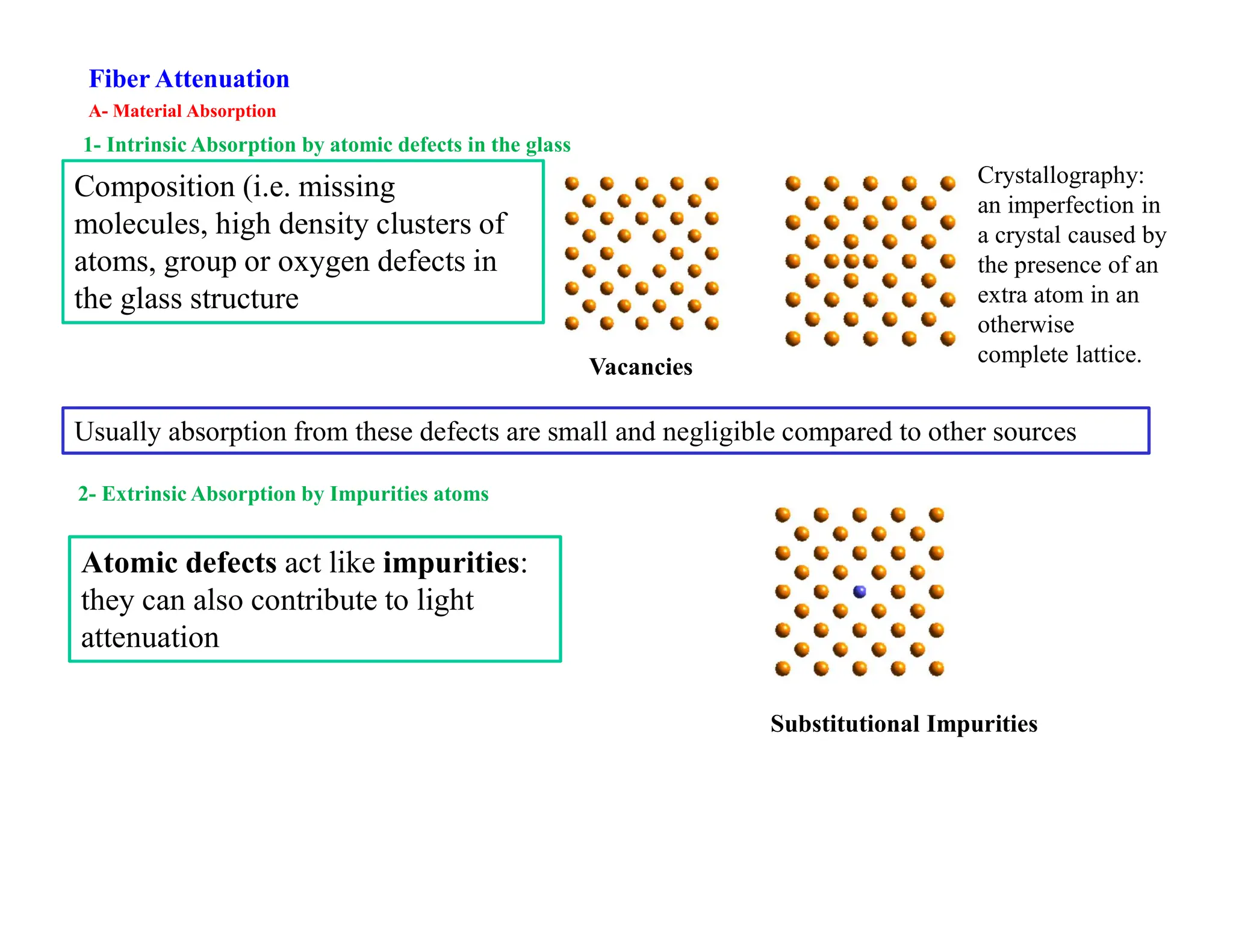
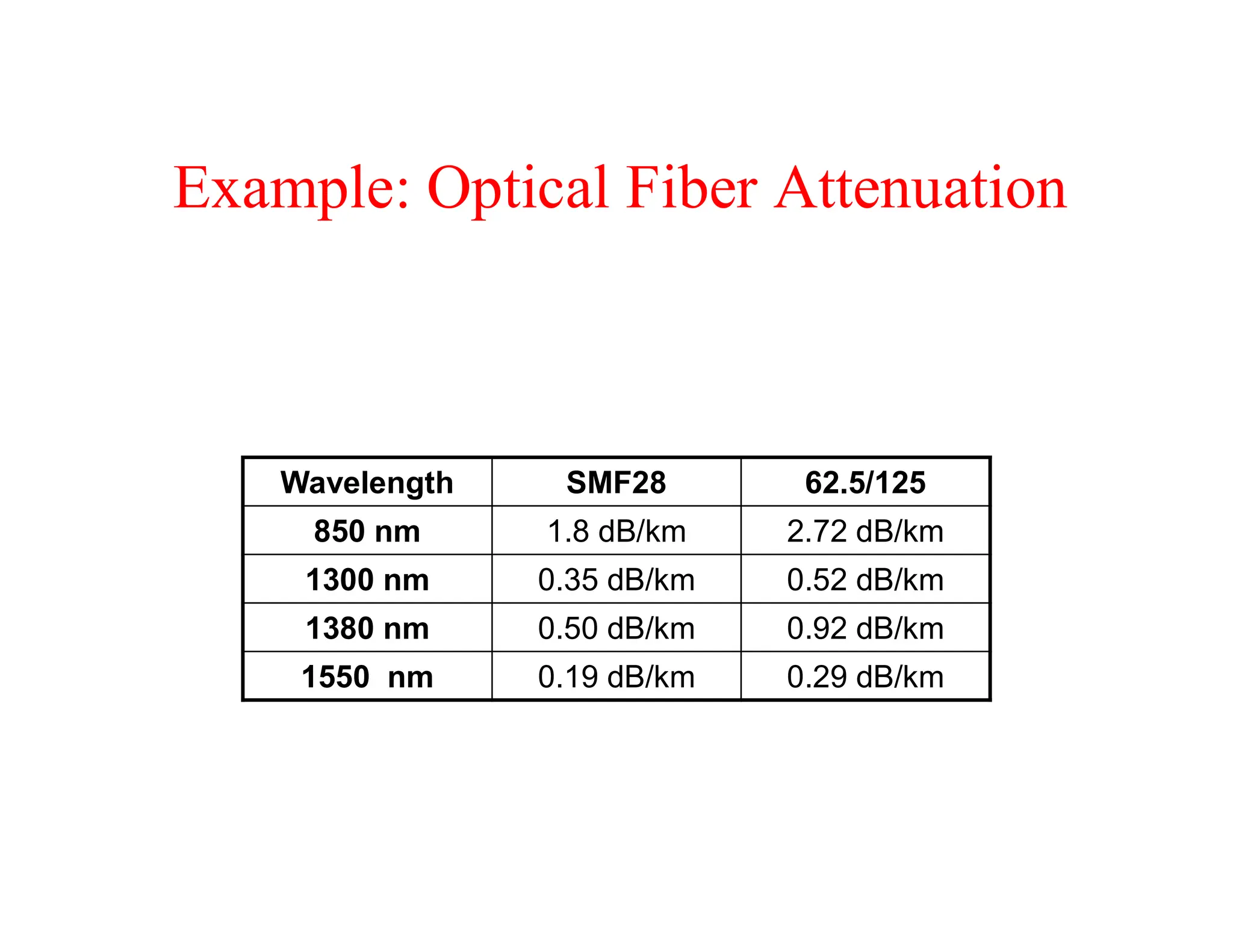
1. Material absorption from defects in the glass fiber material and impurities, which accounts for the majority of losses.
2. Scattering from irregularities in the fiber structure that cause light to change direction.
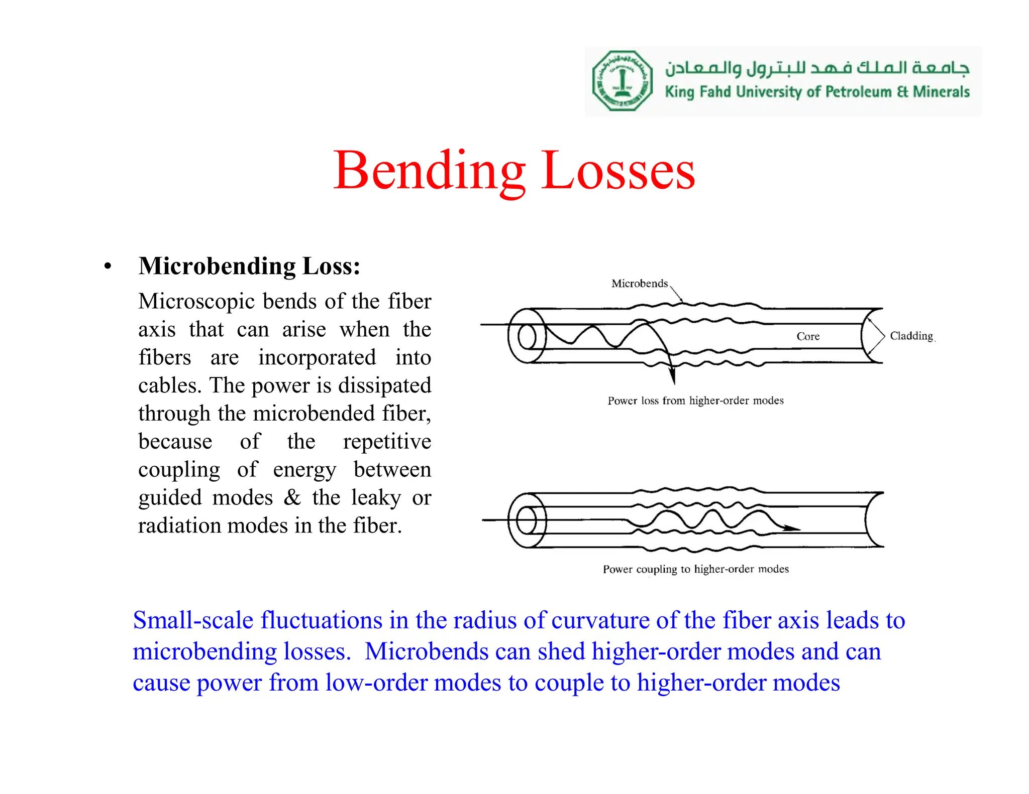
3. Bending losses, where tight bends of the fiber cause light to radiate out of the fiber, with losses increasing sharply for bends below a critical radius.
Signal attenuation limits the maximum distance between optical transmitters and receivers in a fiber system before the signal needs to be regenerated.


![
)
(
)
0
(
log
10
]
dB/km
[
z
P
P
z
Power loss in dB/km
• Where [dBm] or dB milliwat is 10log(P [mW]).
z=0 Z=l
]
dBm
)[
0
(
P
]
km
[
]
dB/km
[
]
dBm
)[
0
(
]
dBm
)[
( l
P
l
P
](https://image.slidesharecdn.com/attenuation-240323234000-3965339c/75/attenuation-of-optical-fiber-communication-systems-pdf-5-2048.jpg)