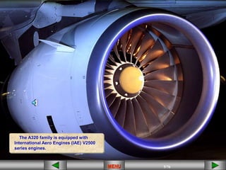
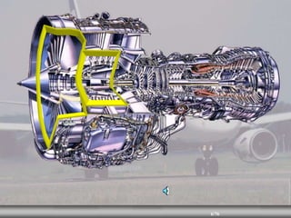
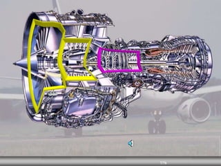
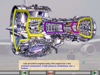
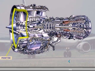
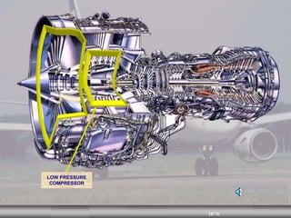
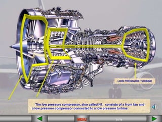
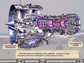
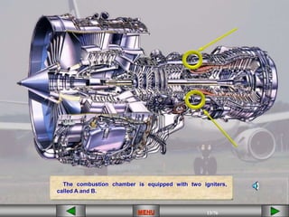
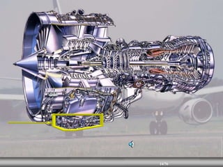
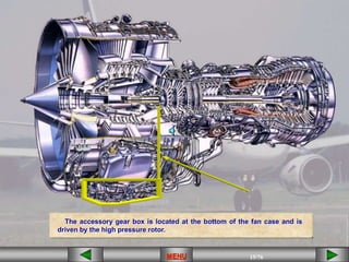
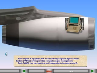
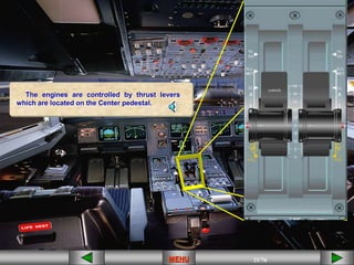
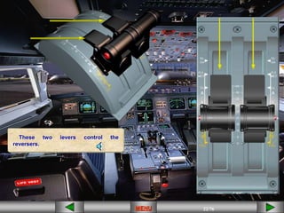
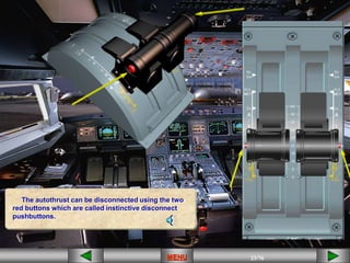
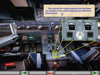
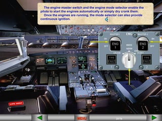
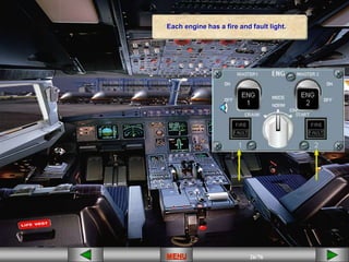
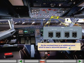
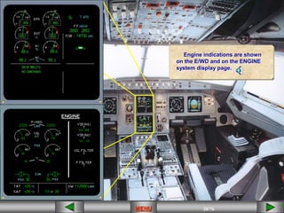
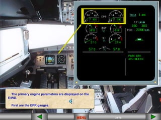
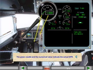
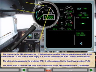
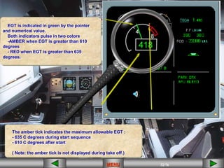
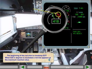
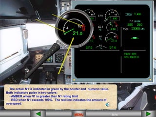
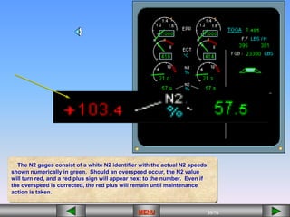
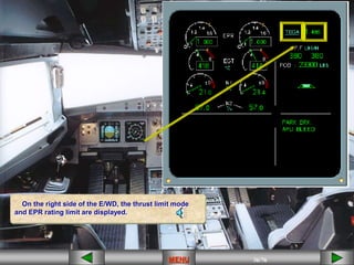
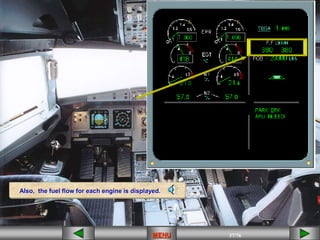
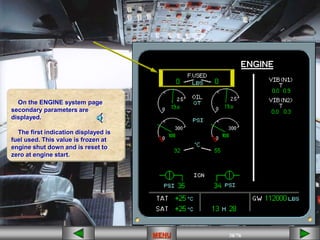
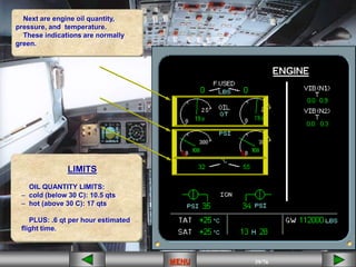
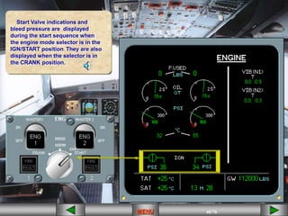
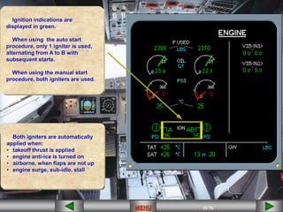
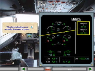
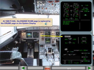
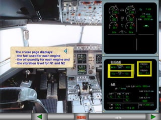
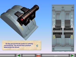
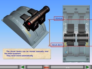
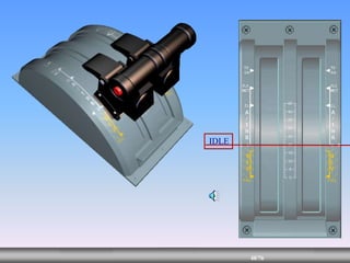
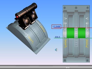
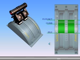
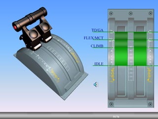
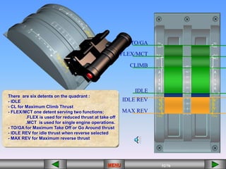
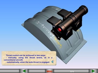
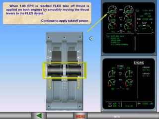
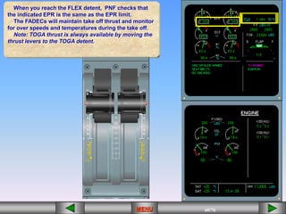
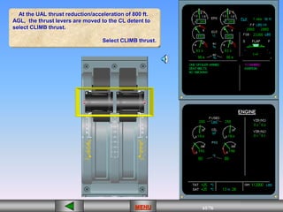
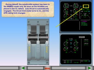
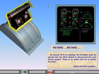
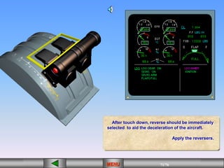
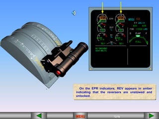
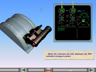
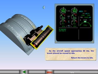
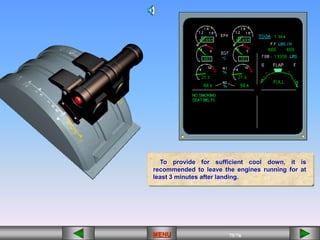
1/43
MENU 1/33
MENU 1/99
MENU 1/76
MENU
MENU
2/43
MENU 2/33
MENU 2/99
MENU 2/76
MENU
MENU
3/43
MENU 3/33
MENU 3/99
MENU 3/76
MENU
OIL QUANTITY
Warm (30c +) = 17.0 qt
Cold (below 30c) = 10.5 qt
MAX START TEMP = 635 c
Plus .6 qt Per hour
MENU
4/43
MENU 4/33
MENU 4/99
MENU 4/76
MENU
STARTER DUTY CYCLE
•2 MIN ON, 15 SEC OFF
•1 MIN ON, 30 MIN OFF
MOTORING:
• 4 MIN ON, 30 MIN OFF
MENU
5/43
MENU 5/33
MENU 5/99
MENU 5/76
MENU
The A320 family is equipped with
International Aero Engines (IAE) V2500
series engines.
MENU
6/43
MENU 6/33
MENU 6/99
MENU 6/76
MENU
7/43
MENU 7/33
MENU 7/99
MENU 7/76
MENU
8/43
MENU 8/33
MENU 8/99
MENU 8/76
MENU
Like all turbine engines today, this engine has a low
pressure compressor, a high pressure compressor, and a
turbine.
MENU
9/43
MENU 9/33
MENU 9/99
MENU 9/76
MENU
FRONT FAN
10/43
MENU 10/33
MENU 10/99
MENU 10/76
MENU
LOW PRESSURE
COMPRESSOR
11/43
MENU 11/33
MENU 11/99
MENU 11/76
MENU
The low pressure compressor, also called N1, consists of a front fan and
a low pressure compressor connected to a low pressure turbine.
LOW PRESSURE TURBINE
MENU
12/43
MENU 12/33
MENU 12/99
MENU 12/76
MENU
The high pressure compressor, also called N2, consists of a high
pressure compressor connected to a high pressure turbine.
HIGH PRESSURE
TURBINE
HIGH PRESSURE
COMPRESSOR
MENU
13/43
MENU 13/33
MENU 13/99
MENU 13/76
MENU
The combustion chamber is equipped with two igniters,
called A and B.
MENU
14/43
MENU 14/33
MENU 14/99
MENU 14/76
MENU
15/43
MENU 15/33
MENU 15/99
MENU 15/76
MENU
The accessory gear box is located at the bottom of the fan case and is
driven by the high pressure rotor.
MENU
16/43
MENU 16/33
MENU 16/99
MENU 16/76
MENU
Each engine is equipped with a Full Authority Digital Engine Control
System (FADEC) which provides complete engine management.
Each FADEC has two identical and independent channels, A and B.
MENU
17/43
MENU 17/33
MENU 17/99
MENU 17/76
MENU
The FADECs are powered by aircraft busses for 5 minutes after power-up, at which
time they “go to sleep.” During engine start, each FADEC becomes powered by a
dedicated alternator, located on the accessory gear case. Therefore, even in the event
of total power failure, the pilot still has full control over the engine.
MENU
18/43
MENU 18/33
MENU 18/99
MENU 18/76
MENU
19/43
MENU 19/33
MENU 19/99
MENU 19/76
MENU
Each engine is equipped with reversers.
MENU
20/43
MENU 20/33
MENU 20/99
MENU 20/76
MENU
MENU
21/43
MENU 21/33
MENU 21/99
MENU 21/76
MENU
controls
The engines are controlled by thrust levers
which are located on the Center pedestal.
MENU
22/43
MENU 22/33
MENU 22/99
MENU 22/76
MENU
These two levers control the
reversers.
MENU
23/43
MENU 23/33
MENU 23/99
MENU 23/76
MENU
The autothrust can be disconnected using the two
red buttons which are called instinctive disconnect
pushbuttons.
MENU
24/43
MENU 24/33
MENU 24/99
MENU 24/76
MENU
The controls for engine starting and shut down
are located on the center pedestal just behind the
thrust levers.
MENU
25/43
MENU 25/33
MENU 25/99
MENU 25/76
MENU
MENU
The engine master switch and the engine mode selector enable the
pilots to start the engines automatically or simply dry crank them.
Once the engines are running, the mode selector can also provide
continuous ignition.
26/43
MENU 26/33
MENU 26/99
MENU 26/76
MENU
Each engine has a fire and fault light.
MENU
27/43
MENU 27/33
MENU 27/99
MENU 27/76
MENU
On the overhead there is an additional panel
which is used in abnormal operation.
MENU
28/43
MENU 28/33
MENU 28/99
MENU 28/76
MENU
MENU
Engine indications are shown
on the E/WD and on the ENGINE
system display page.
29/43
MENU 29/33
MENU 29/99
MENU 29/76
MENU
MENU
The primary engine parameters are displayed on the
E/WD.
First are the EPR gauges.
30/43
MENU 30/33
MENU 30/99
MENU 30/76
MENU
MENU
The green needle and the numerical value indicate the actual EPR.
31/43
MENU 31/33
MENU 31/99
MENU 31/76
MENU
MENU
The blue arc is the EPR command arc; it delineates the transient difference between actual EPR and
command EPR (TLA or throttle lever angle). It is present only when the Auto Throttles are connected.
The white circle represents the predicted EPR; it will correspond to the thrust lever position (TLA).
The amber mark is the max EPR limit; it will correspond to the EPR allowable in the TOGA detent.
32/43
MENU 32/33
MENU 32/99
MENU 32/76
MENU
MENU
The amber tick indicates the maximum allowable EGT :
- 635 C degrees during start sequence
- 610 C degrees after start
( Note: the amber tick is not displayed during take off.)
EGT is indicated in green by the pointer
and numerical value.
Both indicators pulse in two colors
-AMBER when EGT is greater than 610
degrees
- RED when EGT is greater than 635
degrees.
33/43
MENU 33/33
MENU 33/99
MENU 33/76
MENU
MENU
The beginning of the red area is overtemp EGT.
When 635 C degrees is exceeded a red line appears at
the maximum reached value.
34/43
MENU 34/33
MENU 34/99
MENU 34/76
MENU
MENU
The actual N1 is indicated in green by the pointer and numeric value.
Both indicators pulse in two colors:
- AMBER when N1 is greater than N1 rating limit
- RED when N1 exceeds 100%. The red line indicates the amount of
overspeed.
35/43
MENU 35/33
MENU 35/99
MENU 35/76
MENU
The N2 gages consist of a white N2 identifier with the actual N2 speeds
shown numerically in green. Should an overspeed occur, the N2 value
will turn red, and a red plus sign will appear next to the number. Even if
the overspeed is corrected, the red plus will remain until maintenance
action is taken.
36/43
MENU 36/33
MENU 36/99
MENU 36/76
MENU
MENU
On the right side of the E/WD, the thrust limit mode and
On the right side of the E/WD, the thrust limit mode
and EPR rating limit are displayed.
37/43
MENU 37/33
MENU 37/99
MENU 37/76
MENU
MENU
Also, the fuel flow for each engine is displayed.
38/43
MENU 38/33
MENU 38/99
MENU 38/76
MENU
MENU
On the ENGINE system page
secondary parameters are
displayed.
The first indication displayed is
fuel used. This value is frozen at
engine shut down and is reset to
zero at engine start.
39/43
MENU 39/33
MENU 39/99
MENU 39/76
MENU
MENU
Next are engine oil quantity,
pressure, and temperature.
These indications are normally
green.
LIMITS
OIL QUANTITY LIMITS:
– cold (below 30 C): 10.5 qts
– hot (above 30 C): 17 qts
PLUS: .6 qt per hour estimated
flight time.
40/43
MENU 40/33
MENU 40/99
MENU 40/76
MENU
MENU
Start Valve indications and
bleed pressure are displayed
during the start sequence when
the engine mode selector is in the
IGN/START position. They are also
displayed when the selector is in
the CRANK position.
41/43
MENU 41/33
MENU 41/99
MENU 41/76
MENU
MENU
Ignition indications are
displayed in green.
When using the auto start
procedure, only 1 igniter is used,
alternating from A to B with
subsequent starts.
When using the manual start
procedure, both igniters are used.
Both igniters are automatically
applied when:
• takeoff thrust is applied
• engine anti-ice is turned on
• airborne, when flaps are not up
• engine surge, sub-idle, stall
42/43
MENU 42/33
MENU 42/99
MENU 42/76
MENU
MENU
Vibration indications are
normally displayed in green.
43/43
MENU 43/33
MENU 43/99
MENU 43/76
MENU
MENU
At 1500 Ft AGL, the ENGINE ECAM page is replaced by
the CRUISE page on the System Display.
44/43
MENU 44/33
MENU 44/99
MENU 44/76
MENU
MENU
The cruise page displays:
- the fuel used for each engine
- the oil quantity for each engine and
- the vibration level for N1 and N2
MENU
45/43
MENU 45/33
MENU 45/99
MENU 45/76
MENU
MENU
46/43
MENU 46/33
MENU 46/99
MENU 46/76
MENU
On the ground thrust control is entirely
conventional. The thrust lever position
determines the thrust.
MENU
47/43
MENU 47/33
MENU 47/99
MENU 47/76
MENU
The thrust levers can be moved manually over
the entire quadrant.
They never move automatically.
TO/GA
MAX REV
MENU
48/43
MENU 48/33
MENU 48/99
MENU 48/76
MENU
IDLE
49/43
MENU 49/33
MENU 49/99
MENU 49/76
MENU
CLIMB
IDLE
50/43
MENU 50/33
MENU 50/99
MENU 50/76
MENU
CLIMB
FLEX/MCT
IDLE
51/43
MENU 51/33
MENU 51/99
MENU 51/76
MENU
CLIMB
FLEX/MCT
TO/GA
IDLE
52/43
MENU 52/33
MENU 52/99
MENU 52/76
MENU
There are six detents on the quadrant :
- IDLE
- CL for Maximum Climb Thrust
- FLEX/MCT one detent serving two functions:
.FLEX is used for reduced thrust at take off
.MCT is used for single engine operations.
- TO/GA for Maximum Take Off or Go Around thrust
- IDLE REV for idle thrust when reverse selected
- MAX REV for Maximum reverse thrust
CLIMB
FLEX/MCT
TO/GA
MAX REV
IDLE
IDLE REV
MENU
53/43
MENU 53/33
MENU 53/99
MENU 53/76
MENU
Thrust control can be achieved in two ways:
- manually, using the thrust levers, as in a
conventional aircraft,
- automatically, when the auto thrust is engaged.
MENU
54/43
MENU 54/33
MENU 54/99
MENU 54/76
MENU
MENU
55/43
MENU 55/33
MENU 55/99
MENU 55/76
MENU
On ground, the thrust limit mode is TOGA or FLEX .
The selected mode is displayed in the upper right-
hand corner of the E/WD.
TOGA represents the maximum thrust available
from the engine for the actual outside air temperature
(OAT) of the day. The EPR rating limit, displayed
alongside the selected mode, indicates the related
EPR value.
MENU
56/43
MENU 56/33
MENU 56/99
MENU 56/76
MENU
FLEX is used for a reduced thrust take off. To
achieve the thrust reduction an assumed temperature
(or FLEX) is used, for example 45 degrees Celsius.
The FLEX temperature is displayed beside the EPR
rating limit.
This means that the engines will perform as if the
take off was made at full power with the OAT at the
FLEX value.The result is that the actual take off thrust
is reduced, which helps to prolong engine life.
MENU
57/43
MENU 57/33
MENU 57/99
MENU 57/76
MENU
We will demonstrate a FLEX take off since this is
what you will normally do. The first step is to move
the levers from idle to approximately 1.05 EPR.
Click on the thrust levers to apply the thrust.
MENU
58/43
MENU 58/33
MENU 58/99
MENU 58/76
MENU
When 1.05 EPR is reached FLEX take off thrust is
applied on both engines by smoothly moving the thrust
levers to the FLEX detent.
Continue to apply takeoff power.
MENU
59/43
MENU 59/33
MENU 59/99
MENU 59/76
MENU
MENU
60/43
MENU 60/33
MENU 60/99
MENU 60/76
MENU
When you reach the FLEX detent, PNF checks that
the indicated EPR is the same as the EPR limit.
The FADECs will maintain take off thrust and monitor
for over speeds and temperatures during the take off.
Note: TOGA thrust is always available by moving the
thrust levers to the TOGA detent.
MENU
61/43
MENU 61/33
MENU 61/99
MENU 61/76
MENU
At the UAL thrust reduction/acceleration of 800 ft.
AGL, the thrust levers are moved to the CL detent to
select CLIMB thrust.
Select CLIMB thrust.
MENU
62/43
MENU 62/33
MENU 62/99
MENU 62/76
MENU
MENU
63/43
MENU 63/33
MENU 63/99
MENU 63/76
MENU
During takeoff, the autothrottle system has been in
the ARMED mode only. As soon as the throttles are
placed in the CL detent, auto thrust is automatically
engaged. The thrust limit mode turns to CL, and the
EPR rating limit changes.
MENU
64/43
MENU 64/33
MENU 64/99
MENU 64/76
MENU
At 1500 Ft above ground level the ECAM ENGINE
page is replaced by the ECAM CRUISE page on the
system display.
MENU
65/43
MENU 65/33
MENU 65/99
MENU 65/76
MENU
MENU
66/43
MENU 66/33
MENU 66/99
MENU 66/76
MENU
The aircraft is leveling off. Watch the EPR indicators.
When the EPR value changes, an EPR command arc is
displayed in blue, from the current EPR to the new EPR
value. This arc is displayed only when auto thrust is
engaged.
When the new EPR value is reached, the command
arc disappears.
We’ll look at it more closely.
MENU
67/43
MENU 67/33
MENU 67/99
MENU 67/76
MENU
MENU
68/43
MENU 68/33
MENU 68/99
MENU 68/76
MENU
During cruise, descent and approach phases, auto
thrust is normally active, so the thrust levers remain
in the CL detent.
MENU
69/43
MENU 69/33
MENU 69/99
MENU 69/76
MENU
When auto thrust is connected, if both engines should be
at idle (descent), an IDLE indication appears above the EPR
gauges. It flashes for 10 seconds and then remains at
steady green.
Note that there is a difference between ground idle and
flight idle, with flight idle being higher.
MENU
70/43
MENU 70/33
MENU 70/99
MENU 70/76
MENU
At around 30 ft on landing, the throttles must be
placed into the IDLE detent to disconnect the auto
thrust system. There is an audio call out to advise
the pilot.
Select the IDLE position.
RETARD…..RETARD…..
MENU
71/43
MENU 71/33
MENU 71/99
MENU 71/76
MENU
After touch down, reverse should be immediately
selected to aid the deceleration of the aircraft.
Apply the reversers.
MENU
72/43
MENU 72/33
MENU 72/99
MENU 72/76
MENU
On the EPR indicators, REV appears in amber
indicating that the reversers are unstowed and
unlocked.
MENU
73/43
MENU 73/33
MENU 73/99
MENU 73/76
MENU
When the reversers are fully deployed, the REV
indication changes to green.
MENU
74/43
MENU 74/33
MENU 74/99
MENU 74/76
MENU
As the aircraft speed approaches 80 kts, the
levers should be moved to idle.
Return the levers to idle.
MENU
75/43
MENU 75/33
MENU 75/99
MENU 75/76
MENU
To provide for sufficient cool down, it is
recommended to leave the engines running for at
least 3 minutes after landing.
MENU
76/43
MENU 76/33
MENU 76/99
MENU 76/76
MENU
LIST OF SUBJECTS
EXIT PROGRAM
RETURN TO PROGRAM
Throttle Architecture
Throttle Usage
Controls & Indicators
Limitations

70-A.PPT

  • 1.
  • 2.
  • 3.
    3/43 MENU 3/33 MENU 3/99 MENU3/76 MENU OIL QUANTITY Warm (30c +) = 17.0 qt Cold (below 30c) = 10.5 qt MAX START TEMP = 635 c Plus .6 qt Per hour MENU
  • 4.
    4/43 MENU 4/33 MENU 4/99 MENU4/76 MENU STARTER DUTY CYCLE •2 MIN ON, 15 SEC OFF •2 MIN ON, 15 SEC OFF •1 MIN ON, 30 MIN OFF MOTORING: • 4 MIN ON, 30 MIN OFF MENU
  • 5.
    5/43 MENU 5/33 MENU 5/99 MENU5/76 MENU The A320 family is equipped with International Aero Engines (IAE) V2500 series engines. MENU
  • 6.
  • 7.
  • 8.
    8/43 MENU 8/33 MENU 8/99 MENU8/76 MENU Like all turbine engines today, this engine has a low pressure compressor, a high pressure compressor, and a turbine. MENU
  • 9.
    9/43 MENU 9/33 MENU 9/99 MENU9/76 MENU FRONT FAN
  • 10.
    10/43 MENU 10/33 MENU 10/99 MENU10/76 MENU LOW PRESSURE COMPRESSOR
  • 11.
    11/43 MENU 11/33 MENU 11/99 MENU11/76 MENU The low pressure compressor, also called N1, consists of a front fan and a low pressure compressor connected to a low pressure turbine. LOW PRESSURE TURBINE MENU
  • 12.
    12/43 MENU 12/33 MENU 12/99 MENU12/76 MENU The high pressure compressor, also called N2, consists of a high pressure compressor connected to a high pressure turbine. HIGH PRESSURE TURBINE HIGH PRESSURE COMPRESSOR MENU
  • 13.
    13/43 MENU 13/33 MENU 13/99 MENU13/76 MENU The combustion chamber is equipped with two igniters, called A and B. MENU
  • 14.
  • 15.
    15/43 MENU 15/33 MENU 15/99 MENU15/76 MENU The accessory gear box is located at the bottom of the fan case and is driven by the high pressure rotor. MENU
  • 16.
    16/43 MENU 16/33 MENU 16/99 MENU16/76 MENU Each engine is equipped with a Full Authority Digital Engine Control System (FADEC) which provides complete engine management. Each FADEC has two identical and independent channels, A and B. MENU
  • 17.
    17/43 MENU 17/33 MENU 17/99 MENU17/76 MENU The FADECs are powered by aircraft busses for 5 minutes after power-up, at which time they “go to sleep.” During engine start, each FADEC becomes powered by a dedicated alternator, located on the accessory gear case. Therefore, even in the event of total power failure, the pilot still has full control over the engine. MENU
  • 18.
  • 19.
    19/43 MENU 19/33 MENU 19/99 MENU19/76 MENU Each engine is equipped with reversers. MENU
  • 20.
  • 21.
    21/43 MENU 21/33 MENU 21/99 MENU21/76 MENU controls The engines are controlled by thrust levers which are located on the Center pedestal. MENU
  • 22.
    22/43 MENU 22/33 MENU 22/99 MENU22/76 MENU These two levers control the reversers. MENU
  • 23.
    23/43 MENU 23/33 MENU 23/99 MENU23/76 MENU The autothrust can be disconnected using the two red buttons which are called instinctive disconnect pushbuttons. MENU
  • 24.
    24/43 MENU 24/33 MENU 24/99 MENU24/76 MENU The controls for engine starting and shut down are located on the center pedestal just behind the thrust levers. MENU
  • 25.
    25/43 MENU 25/33 MENU 25/99 MENU25/76 MENU MENU The engine master switch and the engine mode selector enable the pilots to start the engines automatically or simply dry crank them. Once the engines are running, the mode selector can also provide continuous ignition.
  • 26.
    26/43 MENU 26/33 MENU 26/99 MENU26/76 MENU Each engine has a fire and fault light. MENU
  • 27.
    27/43 MENU 27/33 MENU 27/99 MENU27/76 MENU On the overhead there is an additional panel which is used in abnormal operation. MENU
  • 28.
    28/43 MENU 28/33 MENU 28/99 MENU28/76 MENU MENU Engine indications are shown on the E/WD and on the ENGINE system display page.
  • 29.
    29/43 MENU 29/33 MENU 29/99 MENU29/76 MENU MENU The primary engine parameters are displayed on the E/WD. First are the EPR gauges.
  • 30.
    30/43 MENU 30/33 MENU 30/99 MENU30/76 MENU MENU The green needle and the numerical value indicate the actual EPR.
  • 31.
    31/43 MENU 31/33 MENU 31/99 MENU31/76 MENU MENU The blue arc is the EPR command arc; it delineates the transient difference between actual EPR and command EPR (TLA or throttle lever angle). It is present only when the Auto Throttles are connected. The white circle represents the predicted EPR; it will correspond to the thrust lever position (TLA). The amber mark is the max EPR limit; it will correspond to the EPR allowable in the TOGA detent.
  • 32.
    32/43 MENU 32/33 MENU 32/99 MENU32/76 MENU MENU The amber tick indicates the maximum allowable EGT : - 635 C degrees during start sequence - 610 C degrees after start ( Note: the amber tick is not displayed during take off.) EGT is indicated in green by the pointer and numerical value. Both indicators pulse in two colors -AMBER when EGT is greater than 610 degrees - RED when EGT is greater than 635 degrees.
  • 33.
    33/43 MENU 33/33 MENU 33/99 MENU33/76 MENU MENU The beginning of the red area is overtemp EGT. When 635 C degrees is exceeded a red line appears at the maximum reached value.
  • 34.
    34/43 MENU 34/33 MENU 34/99 MENU34/76 MENU MENU The actual N1 is indicated in green by the pointer and numeric value. Both indicators pulse in two colors: - AMBER when N1 is greater than N1 rating limit - RED when N1 exceeds 100%. The red line indicates the amount of overspeed.
  • 35.
    35/43 MENU 35/33 MENU 35/99 MENU35/76 MENU The N2 gages consist of a white N2 identifier with the actual N2 speeds shown numerically in green. Should an overspeed occur, the N2 value will turn red, and a red plus sign will appear next to the number. Even if the overspeed is corrected, the red plus will remain until maintenance action is taken.
  • 36.
    36/43 MENU 36/33 MENU 36/99 MENU36/76 MENU MENU On the right side of the E/WD, the thrust limit mode and On the right side of the E/WD, the thrust limit mode and EPR rating limit are displayed.
  • 37.
    37/43 MENU 37/33 MENU 37/99 MENU37/76 MENU MENU Also, the fuel flow for each engine is displayed.
  • 38.
    38/43 MENU 38/33 MENU 38/99 MENU38/76 MENU MENU On the ENGINE system page secondary parameters are displayed. The first indication displayed is fuel used. This value is frozen at engine shut down and is reset to zero at engine start.
  • 39.
    39/43 MENU 39/33 MENU 39/99 MENU39/76 MENU MENU Next are engine oil quantity, pressure, and temperature. These indications are normally green. LIMITS OIL QUANTITY LIMITS: – cold (below 30 C): 10.5 qts – hot (above 30 C): 17 qts PLUS: .6 qt per hour estimated flight time.
  • 40.
    40/43 MENU 40/33 MENU 40/99 MENU40/76 MENU MENU Start Valve indications and bleed pressure are displayed during the start sequence when the engine mode selector is in the IGN/START position. They are also displayed when the selector is in the CRANK position.
  • 41.
    41/43 MENU 41/33 MENU 41/99 MENU41/76 MENU MENU Ignition indications are displayed in green. When using the auto start procedure, only 1 igniter is used, alternating from A to B with subsequent starts. When using the manual start procedure, both igniters are used. Both igniters are automatically applied when: • takeoff thrust is applied • engine anti-ice is turned on • airborne, when flaps are not up • engine surge, sub-idle, stall
  • 42.
    42/43 MENU 42/33 MENU 42/99 MENU42/76 MENU MENU Vibration indications are normally displayed in green.
  • 43.
    43/43 MENU 43/33 MENU 43/99 MENU43/76 MENU MENU At 1500 Ft AGL, the ENGINE ECAM page is replaced by the CRUISE page on the System Display.
  • 44.
    44/43 MENU 44/33 MENU 44/99 MENU44/76 MENU MENU The cruise page displays: - the fuel used for each engine - the oil quantity for each engine and - the vibration level for N1 and N2 MENU
  • 45.
  • 46.
    46/43 MENU 46/33 MENU 46/99 MENU46/76 MENU On the ground thrust control is entirely conventional. The thrust lever position determines the thrust. MENU
  • 47.
    47/43 MENU 47/33 MENU 47/99 MENU47/76 MENU The thrust levers can be moved manually over the entire quadrant. They never move automatically. TO/GA MAX REV MENU
  • 48.
  • 49.
    49/43 MENU 49/33 MENU 49/99 MENU49/76 MENU CLIMB IDLE
  • 50.
    50/43 MENU 50/33 MENU 50/99 MENU50/76 MENU CLIMB FLEX/MCT IDLE
  • 51.
    51/43 MENU 51/33 MENU 51/99 MENU51/76 MENU CLIMB FLEX/MCT TO/GA IDLE
  • 52.
    52/43 MENU 52/33 MENU 52/99 MENU52/76 MENU There are six detents on the quadrant : - IDLE - CL for Maximum Climb Thrust - FLEX/MCT one detent serving two functions: .FLEX is used for reduced thrust at take off .MCT is used for single engine operations. - TO/GA for Maximum Take Off or Go Around thrust - IDLE REV for idle thrust when reverse selected - MAX REV for Maximum reverse thrust CLIMB FLEX/MCT TO/GA MAX REV IDLE IDLE REV MENU
  • 53.
    53/43 MENU 53/33 MENU 53/99 MENU53/76 MENU Thrust control can be achieved in two ways: - manually, using the thrust levers, as in a conventional aircraft, - automatically, when the auto thrust is engaged. MENU
  • 54.
  • 55.
    55/43 MENU 55/33 MENU 55/99 MENU55/76 MENU On ground, the thrust limit mode is TOGA or FLEX . The selected mode is displayed in the upper right- hand corner of the E/WD. TOGA represents the maximum thrust available from the engine for the actual outside air temperature (OAT) of the day. The EPR rating limit, displayed alongside the selected mode, indicates the related EPR value. MENU
  • 56.
    56/43 MENU 56/33 MENU 56/99 MENU56/76 MENU FLEX is used for a reduced thrust take off. To achieve the thrust reduction an assumed temperature (or FLEX) is used, for example 45 degrees Celsius. The FLEX temperature is displayed beside the EPR rating limit. This means that the engines will perform as if the take off was made at full power with the OAT at the FLEX value.The result is that the actual take off thrust is reduced, which helps to prolong engine life. MENU
  • 57.
    57/43 MENU 57/33 MENU 57/99 MENU57/76 MENU We will demonstrate a FLEX take off since this is what you will normally do. The first step is to move the levers from idle to approximately 1.05 EPR. Click on the thrust levers to apply the thrust. MENU
  • 58.
    58/43 MENU 58/33 MENU 58/99 MENU58/76 MENU When 1.05 EPR is reached FLEX take off thrust is applied on both engines by smoothly moving the thrust levers to the FLEX detent. Continue to apply takeoff power. MENU
  • 59.
  • 60.
    60/43 MENU 60/33 MENU 60/99 MENU60/76 MENU When you reach the FLEX detent, PNF checks that the indicated EPR is the same as the EPR limit. The FADECs will maintain take off thrust and monitor for over speeds and temperatures during the take off. Note: TOGA thrust is always available by moving the thrust levers to the TOGA detent. MENU
  • 61.
    61/43 MENU 61/33 MENU 61/99 MENU61/76 MENU At the UAL thrust reduction/acceleration of 800 ft. AGL, the thrust levers are moved to the CL detent to select CLIMB thrust. Select CLIMB thrust. MENU
  • 62.
  • 63.
    63/43 MENU 63/33 MENU 63/99 MENU63/76 MENU During takeoff, the autothrottle system has been in the ARMED mode only. As soon as the throttles are placed in the CL detent, auto thrust is automatically engaged. The thrust limit mode turns to CL, and the EPR rating limit changes. MENU
  • 64.
    64/43 MENU 64/33 MENU 64/99 MENU64/76 MENU At 1500 Ft above ground level the ECAM ENGINE page is replaced by the ECAM CRUISE page on the system display. MENU
  • 65.
  • 66.
    66/43 MENU 66/33 MENU 66/99 MENU66/76 MENU The aircraft is leveling off. Watch the EPR indicators. When the EPR value changes, an EPR command arc is displayed in blue, from the current EPR to the new EPR value. This arc is displayed only when auto thrust is engaged. When the new EPR value is reached, the command arc disappears. We’ll look at it more closely. MENU
  • 67.
  • 68.
    68/43 MENU 68/33 MENU 68/99 MENU68/76 MENU During cruise, descent and approach phases, auto thrust is normally active, so the thrust levers remain in the CL detent. MENU
  • 69.
    69/43 MENU 69/33 MENU 69/99 MENU69/76 MENU When auto thrust is connected, if both engines should be at idle (descent), an IDLE indication appears above the EPR gauges. It flashes for 10 seconds and then remains at steady green. Note that there is a difference between ground idle and flight idle, with flight idle being higher. MENU
  • 70.
    70/43 MENU 70/33 MENU 70/99 MENU70/76 MENU At around 30 ft on landing, the throttles must be placed into the IDLE detent to disconnect the auto thrust system. There is an audio call out to advise the pilot. Select the IDLE position. RETARD…..RETARD….. MENU
  • 71.
    71/43 MENU 71/33 MENU 71/99 MENU71/76 MENU After touch down, reverse should be immediately selected to aid the deceleration of the aircraft. Apply the reversers. MENU
  • 72.
    72/43 MENU 72/33 MENU 72/99 MENU72/76 MENU On the EPR indicators, REV appears in amber indicating that the reversers are unstowed and unlocked. MENU
  • 73.
    73/43 MENU 73/33 MENU 73/99 MENU73/76 MENU When the reversers are fully deployed, the REV indication changes to green. MENU
  • 74.
    74/43 MENU 74/33 MENU 74/99 MENU74/76 MENU As the aircraft speed approaches 80 kts, the levers should be moved to idle. Return the levers to idle. MENU
  • 75.
    75/43 MENU 75/33 MENU 75/99 MENU75/76 MENU To provide for sufficient cool down, it is recommended to leave the engines running for at least 3 minutes after landing. MENU
  • 76.
    76/43 MENU 76/33 MENU 76/99 MENU76/76 MENU LIST OF SUBJECTS EXIT PROGRAM RETURN TO PROGRAM Throttle Architecture Throttle Usage Controls & Indicators Limitations

Editor's Notes