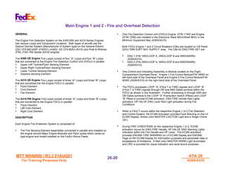
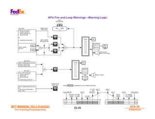
The document provides information on the fire protection systems for the A300 and A310 aircraft. It describes the engine fire protection systems which utilize fire detection and control modules to detect fires and activate extinguishing systems. The modules close valves, shut down electrical power and ignite squibs to discharge extinguishing bottles when the fire handle is pulled. Circuit breakers for the fire systems are located on panels in the flight compartment. Smoke detection systems monitor various cargo areas and compartments.
Preparation and Observation Checklist To Improve Interviewing Skills HandoutRobert Davis
This checklist can help the learner improve his/her interviewing technique in qualitative interviewing as well as help observers to provide feedback to interviewers on technique.
Preparation and Observation Checklist To Improve Interviewing Skills HandoutRobert Davis
This checklist can help the learner improve his/her interviewing technique in qualitative interviewing as well as help observers to provide feedback to interviewers on technique.
Thermal Power Plant - Full Detail About Plant and Parts (Also Contain Animate...Shubham Thakur
A thermal power station is a power plant in which the prime mover is steam driven. Water is heated, turns into steam and spins a steam turbine which drives an electrical generator. After it passes through the turbine, the steam is condensed in a condenser and recycled to where it was heated; this is known as a Rankine cycle. The greatest variation in the design of thermal power stations is due to the different fossil fuel resources generally used to heat the water. Some prefer to use the term energy center because such facilities convert forms of heat energy into electrical energy.[1] Certain thermal power plants also are designed to produce heat energy for industrial purposes of district heating, or desalination of water, in addition to generating electrical power. Globally, fossil fueled thermal power plants produce a large part of man-made CO2 emissions to the atmosphere, and efforts to reduce these are varied and widespread.
For Video on Themal Power Plant (Animated Working Video) :- https://www.youtube.com/watch?v=ouWOhk1INjo
Subscribe To Our Youtube Channel For More Videos:-
https://www.youtube.com/TheEngineeringScienc
Click Here To Subscribe:-
http://www.youtube.com/user/TheEngineeringScienc?sub_confirmation=1
A Fire Alarm Control Panel (FACP) / Fire Alarm Control Unit (FACU), is an electric panel that is the controlling component of a fire alarm system which is installed at various places as a protective measure against fire; sounds an alarm when actuated by a fire detection system. Fire Alarm System is essential to warn all occupants that a fire or emergency situation exists. Sometimes fire detection and alarm systems are used to compensate or to give special cover for items of high value. In case of fire early detection of smoke and heat helps in fighting the fire effectively & extinguishing it in nascent stage. Thus by early detection, we can prevent the fire from spreading in turn saving life and loss of property and business.
Understanding HVAC systems is essential for its proper maintenance. Quarterly maintenance of your HVAC systems is important to extend the system’s lifespan and save hundreds of dollars on unexpected repairs. Regular maintenance of residential HVAC systems is essential when it comes not only to the proper function of boilers, furnaces, and AC units but also for better energy efficiency and in-home air quality. A properly maintained HVAC system can cut hydro costs from five to ten percent, as well as improving comfort and air quality.
For More info:
https://sierraair.ca/residential/
Detailed Internship Report about RAJIV GANDHI COMBINED CYCLE POWER PLANT-NTPC LTD. Includes information about Thermodynamic Cycles, Combined Cycle, HRSG (Heat Recovery Steam Generator), and various components of a Combined Cycle Power Plant.
TECHNICAL TRAINING MANUAL GENERAL FAMILIARIZATION COURSEDuvanRamosGarzon1
AIRCRAFT GENERAL
The Single Aisle is the most advanced family aircraft in service today, with fly-by-wire flight controls.
The A318, A319, A320 and A321 are twin-engine subsonic medium range aircraft.
The family offers a choice of engines
Hierarchical Digital Twin of a Naval Power SystemKerry Sado
A hierarchical digital twin of a Naval DC power system has been developed and experimentally verified. Similar to other state-of-the-art digital twins, this technology creates a digital replica of the physical system executed in real-time or faster, which can modify hardware controls. However, its advantage stems from distributing computational efforts by utilizing a hierarchical structure composed of lower-level digital twin blocks and a higher-level system digital twin. Each digital twin block is associated with a physical subsystem of the hardware and communicates with a singular system digital twin, which creates a system-level response. By extracting information from each level of the hierarchy, power system controls of the hardware were reconfigured autonomously. This hierarchical digital twin development offers several advantages over other digital twins, particularly in the field of naval power systems. The hierarchical structure allows for greater computational efficiency and scalability while the ability to autonomously reconfigure hardware controls offers increased flexibility and responsiveness. The hierarchical decomposition and models utilized were well aligned with the physical twin, as indicated by the maximum deviations between the developed digital twin hierarchy and the hardware.
NO1 Uk best vashikaran specialist in delhi vashikaran baba near me online vas...Amil Baba Dawood bangali
Contact with Dawood Bhai Just call on +92322-6382012 and we'll help you. We'll solve all your problems within 12 to 24 hours and with 101% guarantee and with astrology systematic. If you want to take any personal or professional advice then also you can call us on +92322-6382012 , ONLINE LOVE PROBLEM & Other all types of Daily Life Problem's.Then CALL or WHATSAPP us on +92322-6382012 and Get all these problems solutions here by Amil Baba DAWOOD BANGALI
#vashikaranspecialist #astrologer #palmistry #amliyaat #taweez #manpasandshadi #horoscope #spiritual #lovelife #lovespell #marriagespell#aamilbabainpakistan #amilbabainkarachi #powerfullblackmagicspell #kalajadumantarspecialist #realamilbaba #AmilbabainPakistan #astrologerincanada #astrologerindubai #lovespellsmaster #kalajaduspecialist #lovespellsthatwork #aamilbabainlahore#blackmagicformarriage #aamilbaba #kalajadu #kalailam #taweez #wazifaexpert #jadumantar #vashikaranspecialist #astrologer #palmistry #amliyaat #taweez #manpasandshadi #horoscope #spiritual #lovelife #lovespell #marriagespell#aamilbabainpakistan #amilbabainkarachi #powerfullblackmagicspell #kalajadumantarspecialist #realamilbaba #AmilbabainPakistan #astrologerincanada #astrologerindubai #lovespellsmaster #kalajaduspecialist #lovespellsthatwork #aamilbabainlahore #blackmagicforlove #blackmagicformarriage #aamilbaba #kalajadu #kalailam #taweez #wazifaexpert #jadumantar #vashikaranspecialist #astrologer #palmistry #amliyaat #taweez #manpasandshadi #horoscope #spiritual #lovelife #lovespell #marriagespell#aamilbabainpakistan #amilbabainkarachi #powerfullblackmagicspell #kalajadumantarspecialist #realamilbaba #AmilbabainPakistan #astrologerincanada #astrologerindubai #lovespellsmaster #kalajaduspecialist #lovespellsthatwork #aamilbabainlahore #Amilbabainuk #amilbabainspain #amilbabaindubai #Amilbabainnorway #amilbabainkrachi #amilbabainlahore #amilbabaingujranwalan #amilbabainislamabad
Saudi Arabia stands as a titan in the global energy landscape, renowned for its abundant oil and gas resources. It's the largest exporter of petroleum and holds some of the world's most significant reserves. Let's delve into the top 10 oil and gas projects shaping Saudi Arabia's energy future in 2024.
Immunizing Image Classifiers Against Localized Adversary Attacksgerogepatton
This paper addresses the vulnerability of deep learning models, particularly convolutional neural networks
(CNN)s, to adversarial attacks and presents a proactive training technique designed to counter them. We
introduce a novel volumization algorithm, which transforms 2D images into 3D volumetric representations.
When combined with 3D convolution and deep curriculum learning optimization (CLO), itsignificantly improves
the immunity of models against localized universal attacks by up to 40%. We evaluate our proposed approach
using contemporary CNN architectures and the modified Canadian Institute for Advanced Research (CIFAR-10
and CIFAR-100) and ImageNet Large Scale Visual Recognition Challenge (ILSVRC12) datasets, showcasing
accuracy improvements over previous techniques. The results indicate that the combination of the volumetric
input and curriculum learning holds significant promise for mitigating adversarial attacks without necessitating
adversary training.
About
Indigenized remote control interface card suitable for MAFI system CCR equipment. Compatible for IDM8000 CCR. Backplane mounted serial and TCP/Ethernet communication module for CCR remote access. IDM 8000 CCR remote control on serial and TCP protocol.
• Remote control: Parallel or serial interface.
• Compatible with MAFI CCR system.
• Compatible with IDM8000 CCR.
• Compatible with Backplane mount serial communication.
• Compatible with commercial and Defence aviation CCR system.
• Remote control system for accessing CCR and allied system over serial or TCP.
• Indigenized local Support/presence in India.
• Easy in configuration using DIP switches.
Technical Specifications
Indigenized remote control interface card suitable for MAFI system CCR equipment. Compatible for IDM8000 CCR. Backplane mounted serial and TCP/Ethernet communication module for CCR remote access. IDM 8000 CCR remote control on serial and TCP protocol.
Key Features
Indigenized remote control interface card suitable for MAFI system CCR equipment. Compatible for IDM8000 CCR. Backplane mounted serial and TCP/Ethernet communication module for CCR remote access. IDM 8000 CCR remote control on serial and TCP protocol.
• Remote control: Parallel or serial interface
• Compatible with MAFI CCR system
• Copatiable with IDM8000 CCR
• Compatible with Backplane mount serial communication.
• Compatible with commercial and Defence aviation CCR system.
• Remote control system for accessing CCR and allied system over serial or TCP.
• Indigenized local Support/presence in India.
Application
• Remote control: Parallel or serial interface.
• Compatible with MAFI CCR system.
• Compatible with IDM8000 CCR.
• Compatible with Backplane mount serial communication.
• Compatible with commercial and Defence aviation CCR system.
• Remote control system for accessing CCR and allied system over serial or TCP.
• Indigenized local Support/presence in India.
• Easy in configuration using DIP switches.
Sachpazis:Terzaghi Bearing Capacity Estimation in simple terms with Calculati...Dr.Costas Sachpazis
Terzaghi's soil bearing capacity theory, developed by Karl Terzaghi, is a fundamental principle in geotechnical engineering used to determine the bearing capacity of shallow foundations. This theory provides a method to calculate the ultimate bearing capacity of soil, which is the maximum load per unit area that the soil can support without undergoing shear failure. The Calculation HTML Code included.
Hybrid optimization of pumped hydro system and solar- Engr. Abdul-Azeez.pdffxintegritypublishin
Advancements in technology unveil a myriad of electrical and electronic breakthroughs geared towards efficiently harnessing limited resources to meet human energy demands. The optimization of hybrid solar PV panels and pumped hydro energy supply systems plays a pivotal role in utilizing natural resources effectively. This initiative not only benefits humanity but also fosters environmental sustainability. The study investigated the design optimization of these hybrid systems, focusing on understanding solar radiation patterns, identifying geographical influences on solar radiation, formulating a mathematical model for system optimization, and determining the optimal configuration of PV panels and pumped hydro storage. Through a comparative analysis approach and eight weeks of data collection, the study addressed key research questions related to solar radiation patterns and optimal system design. The findings highlighted regions with heightened solar radiation levels, showcasing substantial potential for power generation and emphasizing the system's efficiency. Optimizing system design significantly boosted power generation, promoted renewable energy utilization, and enhanced energy storage capacity. The study underscored the benefits of optimizing hybrid solar PV panels and pumped hydro energy supply systems for sustainable energy usage. Optimizing the design of solar PV panels and pumped hydro energy supply systems as examined across diverse climatic conditions in a developing country, not only enhances power generation but also improves the integration of renewable energy sources and boosts energy storage capacities, particularly beneficial for less economically prosperous regions. Additionally, the study provides valuable insights for advancing energy research in economically viable areas. Recommendations included conducting site-specific assessments, utilizing advanced modeling tools, implementing regular maintenance protocols, and enhancing communication among system components.
Explore the innovative world of trenchless pipe repair with our comprehensive guide, "The Benefits and Techniques of Trenchless Pipe Repair." This document delves into the modern methods of repairing underground pipes without the need for extensive excavation, highlighting the numerous advantages and the latest techniques used in the industry.
Learn about the cost savings, reduced environmental impact, and minimal disruption associated with trenchless technology. Discover detailed explanations of popular techniques such as pipe bursting, cured-in-place pipe (CIPP) lining, and directional drilling. Understand how these methods can be applied to various types of infrastructure, from residential plumbing to large-scale municipal systems.
Ideal for homeowners, contractors, engineers, and anyone interested in modern plumbing solutions, this guide provides valuable insights into why trenchless pipe repair is becoming the preferred choice for pipe rehabilitation. Stay informed about the latest advancements and best practices in the field.
Final project report on grocery store management system..pdfKamal Acharya
In today’s fast-changing business environment, it’s extremely important to be able to respond to client needs in the most effective and timely manner. If your customers wish to see your business online and have instant access to your products or services.
Online Grocery Store is an e-commerce website, which retails various grocery products. This project allows viewing various products available enables registered users to purchase desired products instantly using Paytm, UPI payment processor (Instant Pay) and also can place order by using Cash on Delivery (Pay Later) option. This project provides an easy access to Administrators and Managers to view orders placed using Pay Later and Instant Pay options.
In order to develop an e-commerce website, a number of Technologies must be studied and understood. These include multi-tiered architecture, server and client-side scripting techniques, implementation technologies, programming language (such as PHP, HTML, CSS, JavaScript) and MySQL relational databases. This is a project with the objective to develop a basic website where a consumer is provided with a shopping cart website and also to know about the technologies used to develop such a website.
This document will discuss each of the underlying technologies to create and implement an e- commerce website.
1. MTT M540000 / R3.3 01AUG01
MTT M540000 / R3.3 01AUG01
For Training Purposes Only
ATA 26
ATA 26
A300/A310
A300/A310
26-
26-1
1
ATA 26
ATA 26
Fire Protection
Fire Protection
2. MTT M540000 / R3.3 01AUG01
MTT M540000 / R3.3 01AUG01
For Training Purposes Only
ATA 26
ATA 26
A300/A310
A300/A310
26-
26-2
2
THIS PAGE INTENTIONALLY
LEFT BLANK
3. MTT M540000 / R3.3 01AUG01
MTT M540000 / R3.3 01AUG01
For Training Purposes Only
ATA 26
ATA 26
A300/A310
A300/A310
26-
26-3
3
FIRE PROTECTION
SYSTEMS - GENERAL
4. MTT M540000 / R3.3 01AUG01
MTT M540000 / R3.3 01AUG01
For Training Purposes Only
ATA 26
ATA 26
A300/A310
A300/A310
26-
26-4
4
GENERAL
The Fire Protection Systems on the FedEx Airbus Fleet are designed to
detect, warn and extinguish a fire in either Main Engine Nacelle Number
1 or 2. Each Engine Fire Protection Fire Detection Control Unit (FDCU)
provides detection and warnings to the Flight Compartment Overhead
Panel. The Fire Warning Module(s) for Engine 1/FIN 39WD and Engine
2/FIN 40WD (A300/A310) have features for detection, control,
extinguishing and testing the respective system. Each FDCU has BITE
features for testing and troubleshooting the respective engine system.
The APU Fire Protection System consist of a Fire Warning Control
Module/FIN 20WG (A300/A310) on the Flight Compartment Overhead
Panel. A Fire Extinguishing Bottle/FIN 11WF (A300/A310) in the
Fuselage Tail Section located on the forward face of Fuselage Frame
(FR95) (A300/A310). The system detects, warns, and extinguishes fire
automatically on the ground and manual mode of extinguishing during
flight conditions. BITE features are provided on the APU FDCU/FIN
13WG located on Shelf 91VU in the Electronic Rack 90VU in the
Avionics Compartment (A300/A310).
The Main Deck Cargo Compartment (MDCC) is equipped with Smoke
Detection System in the Compartment Zones (MID 1, MID 2 and AFT)
(A300/A310). There are no Fire Extinguishing Bottles for the
Compartment Zones. The detection of smoke in the zones provide
signals to Electronic Rack 80VU in the Avionics Compartment to the
affected MDCC Smoke Detector Control Units/FIN Numbers 50WU1
(MID 1), 50WU2 (MID 2) or 50WU3 (AFT) (A300/A310). The units send
signals to the MAIN DECK CARGO SMOKE DET Panel 433VU on the
Flight Compartment Overhead Panel (A300/A310). The MID 1 (FWD)
Zone is equipped with three Fire Extinguisher Bottles for HAZ CANS
(Hazardous Material) which carry flammable/combustible materials for
customer delivery parcels and cargo items (A300/A310).
The Lower Cargo Compartments (FORWARD/FWD, AFT and BULK)
have smoke detection, warning and extinguishing features. Smoke
Detectors are located in the ceiling of these compartment areas
(A300/A310). The Detector Unit(s) (A and B Loops) may vary on some
A310 aircraft with either two (A and B Loops) or four loops (two A Loops
and two B Loops) in each of the three lower bay areas (FWD, AFT and
BULK). The A300 Detector Units (A and B Loops) located in all three
cargo bay areas have two loops in each bay area (FWD, AFT and
BULK) provide signals to the Flight Compartment Overhead Panel
433VU (A300) and 448VU (A310). The CARGO COMPT SMOKE DET
Panel 433VU in the Flight Compartment has Fire Bottle Extinguishing
Controls and Indicators (A300/A310). The FWD or AFT (including
BULK) Cargo Compartments can extinguish fire or smother fire within
these sealed areas with two bottles mounted in the FWD Cargo
Compartment (Located forward right hand side of compartment).
The Avionics Compartment has Smoke Detection System(s) for the
following area(s):
• Main Bay Smoke Detection (Avionics areas) (Inertial Reference
System (IRS) Number 2 Unit is incorporated within this detection
system)
• Cockpit Smoke Detector (Flight Deck areas)
• Minimum Equipment Bay Smoke Detector (Electronic Rack
90VU/Shelf 96VU and IRS 1 and 3 Units, these location(s) are
separately sealed compartments)
The Cockpit and Main Bay Smoke Detection System both utilize the
same Warning Light (AVIONICS SMOKE). The Minimum Equipment
Bay Smoke Detection System provides smoke warnings on the Flight
Compartment Overhead Circuit Breaker (CB) Panel 22VU in the
“MINIMUM EQUIPT BAY” CB area. The System(s) detect smoke in the
Electronic Equipment Cooling Ducts expelled by malfunctioning
equipment boxes due to internal component or electrical failures.
A300 / A310 Fire Detection and Extinguishing Systems
5. MTT M540000 / R3.3 01AUG01
MTT M540000 / R3.3 01AUG01
For Training Purposes Only
ATA 26
ATA 26
A300/A310
A300/A310
26-
26-5
5
A300/A310 Fire Detection and Extinguishing Systems - Layout
LOWER
Typical Layout -
Typical Layout -
A300/A310
A300/A310
6. MTT M540000 / R3.3 01AUG01
MTT M540000 / R3.3 01AUG01
For Training Purposes Only
ATA 26
ATA 26
A300/A310
A300/A310
26-
26-6
6
Location of Fire Protection System Circuit Breakers
GENERAL DESCRIPTION
The Fire Protection Systems Circuit Breaker (CB) Panels on the A300 and A310
aircraft have differences on Panel Locations, Panel Numbers and specific CB
function items. The CB Panels are located in the Flight Compartment area.
The A300/A310 CB Panel 22VU has the following CBs on them for the Fire
Protection Systems on each model of aircraft:
• FIRE EXTING/CARGO COMPT BOTTLE (BLT) 1 and 2 (Two CBs)
• ENG 1 & 2 SQUIB “B”/BLT 1 & 2 (Two CBs)
Also, located on Panel 22VU in the MIN EQPT BAY SUPPLY CB area are the
following CBs for the A300/A310 aircraft:
• ENG FIRE DET/ENG 1 LOOP “A” and LOOP “B” (Two CBs) and WARN
(One CB)
• ENG FIRE DET/ENG 2 LOOP “A” and LOOP “B” (Two CBs) and WARN
(One CB)
The other Fire Protection System Panels on the A300 and A310 aircraft have
different Panel Number(s) and Location of Panel Area(s):
• A300-600 Aircraft Registration Numbers N650FE thru N686FE have the
following features on the Distribution Panel 133VU/ENGINES Section
located on the Flight Compartment rear wall area:
• ENG 1 & 2/FIRE EXTING SQUIB “A” BTL 1 and 2
• A310-200 Series Aircraft Registration Numbers N401FE thru N454FE have
the following features on the Distribution Panel 123VU/ENGINES Section
located on the Flight Compartment rear wall area :
• ENG 1 & 2/FIRE EXTING SQUIB “A” BTL 1 and 2
Some of the Fire Protection Systems CBs are monitored to detect CBs which
have been “Open” or “Left Open” for flight and/or ground condition(s) by
maintenance personnel. The CB Monitoring System performs these functions to
alert flight or ground crews of these conditions. The Airbus Aircraft Maintenance
Manual (AMM) ATA Chapter 31-69-00 provides information on the CB Monitoring
System for Description, Operation, Test and Adjustment.
The Monitored CBs have GREEN color pull/push caps with imprinted amperage
rating on the cap in white numbers. The Monitored CBs are incorporated in the
ECAM System and on the Maintenance Panels 472VU (C/B MONITOR Panel)
(A300/A310) to provide warnings to crews. The system will be covered in ATA
Chapter 31 of Level 3 Training Manual.
The A300-600 aircraft do not have any Configuration 1 and 2 as defined on the
A310-Series in the FedEx Airbus Fleets. The A310-Series aircraft have
Configuration(s) 1 and 2 due to the mix of Airbus Industries Manufacturer’s Serial
Number (MSN) within the FedEx Airbus Fleets (A300/A310). The following
aircraft have CB Monitoring of the Fire Protection Systems CBs:
A300- 600 Monitored CBs on CB Panel(s):
Panel 22VU
• FIRE EXTING-CARGO COMPT BTL 1 and 2 (Two CBs)
Panel 131VU
• APU - FIRE EXTING - SQUIB “A” and “B”(Two CBs)
• APU - FIRE EXTING - SQUIB TEST (One CB)
• APU - FIRE EXTING - AUTO EXTING GND TEST (One CB)
7. MTT M540000 / R3.3 01AUG01
MTT M540000 / R3.3 01AUG01
For Training Purposes Only
ATA 26
ATA 26
A300/A310
A300/A310
26-
26-7
7
A300 Fire Protection System - Circuit Breakers Location
8. MTT M540000 / R3.3 01AUG01
MTT M540000 / R3.3 01AUG01
For Training Purposes Only
ATA 26
ATA 26
A300/A310
A300/A310
26-
26-8
8
A310 Fire Protection System - Circuit Breakers Location
A310-200 Series Monitored CBs on CB Panel(s):
Panel 22VU
• AVIONICS SMOKE DET - SUPPLY NORM and STBY (ALL)
• AVIONICS SMOKE DET - MONITOR (One CB) (ALL)
• ENG FIRE DET - ENG 1 and ENG 2 - LOOP “A” (Two CBs) For A/C 401 –
405, 407 - 414
• ENG FIRE DET - ENG 1 and ENG 2 - LOOP “B” (Two CBs) For A/C 401 –
405, 407 - 414
• CARGO SMOKE DET – PWR SUPPLY (One CB)
ON A/C 415-415, 420 - 430, 442 - 443, 445 - 450, 453 - 499
• FIRE EXTING – CARGO COMPT BTL 1 and 2 (Two CBs) (ALL)
Panel 123VU
• APU FIRE DET – LOOP “A” and “B” (Two CBs)
9. MTT M540000 / R3.3 01AUG01
MTT M540000 / R3.3 01AUG01
For Training Purposes Only
ATA 26
ATA 26
A300/A310
A300/A310
26-
26-9
9
THIS PAGE INTENTIONALLY
LEFT BLANK
10. MTT M540000 / R3.3 01AUG01
MTT M540000 / R3.3 01AUG01
For Training Purposes Only
ATA 26
ATA 26
A300/A310
A300/A310
26-
26-10
10
THIS PAGE INTENTIONALLY
LEFT BLANK
11. MTT M540000 / R3.3 01AUG01
MTT M540000 / R3.3 01AUG01
For Training Purposes Only
ATA 26
ATA 26
A300/A310
A300/A310
26-
26-11
11
ENGINE FIRE
PROTECTION SYSTEM
12. MTT M540000 / R3.3 01AUG01
MTT M540000 / R3.3 01AUG01
For Training Purposes Only
ATA 26
ATA 26
A300/A310
A300/A310
26-
26-12
12
Engine Fire Protection - Controls & Indicators
ENGINE FIRE PROTECTION CONTROLS
Two identical ENG Fire Control Modules (Panels)/FIN 39WD (Engine 1) and
40WD (Engine 2) with fire handles are provided for control of Fire Detection and
Extinguishing.
Both Engine Fire Protection Systems are energized when the DC ESS BUS is
powered from various sources. Electrical power can be provided for fire
extinguishing operation from the DC NORMAL BUS FIN1PP to the DC ESS BUS
FIN3PP and from the three Aircraft Batteries (BAT 1/FIN 10PE, BAT 2/FIN 9PE
and BAT 3/FIN 8PE). Also, from the AC ESS BUS (AC ESS BUS1/FIN 3XP1)
(A300/A310). The main bus for electrical power is the DC ESS BUS.
ENGINE 1 or 2 FIRE HANDLE
The ENG FIRE handles have two positions. The ENG Fire Warning Light is
integrated into the fire handles. The following condition(s) occur during operation
of the fire handle:
• IN:
• Normal position, mechanically locked and safety lock device
is lockwired with breakaway wire
• PULLED
• Pulling the fire handle electrically causes the respective engine to
CLOSE the following system component(s):
• ENG FUEL LP VALVE
• ENG HYD FIRE VALVE
• ENG AIR BLD HP VALVE
• ENG BLD VALVE (Pressure Regulating Valve)
• X FEED Valve (Pneumatic Cross Feed Valve) (If in AUTO position)
• PACK VALVE 1 OR 2 (Associated with relevant engine)
• WING ANTI ICE VALVES (Two Normal and two Alternate Valves on
each Wing (A300/A310)
• ELEC PWR GEN (De-energized)
• CRC (Continuous Repetitive Chime) (Silencing CRC and LOOP
Light extinguishing, SQUIB Light illumination)
• ENG ANTI ICE VALVE (Valve will CLOSE due to loss of pneumatic
pressure supply. FAULT Light will illuminate.)
1. ENG 1 or 2 FIRE HANDLE
The eight RED color lights in the handle will illuminate independently of
handle position as long as the respective Engine Fire Warning is activated.
The lights extinguish when the temperature, detected by the Fire Loops,
decrease below the warning threshold or lowest level which warning
occurred.
Illumination of the ENG 1 or 2 Fire Light is accompanied by ECAM activation
and illumination of the HP FUEL VALVE Red color light on the ENG 1 or 2
FUEL Lever when selected “ON”.
2. AGENT 1 or 2 PUSHBUTTON
The Pushbutton Switches (PBsw) controls the ignition of the Squibs and
discharging of the Fire Extinguishing Bottle. The PBsw is ARMED only when
the related ENG FIRE Handle is pulled:
• MOMENTARILY PRESSED
With ENG FIRE Handle pulled, the selected Squib (AGENT 1 or 2) is
ignited for fire bottle discharge.
• RELEASED
The Squibs (Agent 1 or 2) electrical circuit is de-energized.
• SQUIB
The White color light illuminates when the ENG FIRE Handle is pulled to
identify the respective AGENT 1 or 2 PBsw to be activated to discharge
the Fire Bottle. During SQUIB TEST, the light illuminates to indicate a
successful test of the squib electrical circuit.
• DISCH
The Amber color DISCH Light illuminates when the related Fire
Extinguisher Bottle is discharged.
13. MTT M540000 / R3.3 01AUG01
MTT M540000 / R3.3 01AUG01
For Training Purposes Only
ATA 26
ATA 26
A300/A310
A300/A310
26-
26-13
13
Engine Fire Protection - Controls & Indicators
1 1
2 2
A B
14. MTT M540000 / R3.3 01AUG01
MTT M540000 / R3.3 01AUG01
For Training Purposes Only
ATA 26
ATA 26
A300/A310
A300/A310
26-
26-14
14
Engine Fire Protection - Controls & Indicators
3. SQUIB TEST PUSHBUTTON
The Pushbutton Switch (PBsw) controls the test of the squibs in the
Fire Bottle Discharge Heads and their electrical circuits. When
pressed with the respective ENG FIRE Handle in normal position
(IN), the two SQUIB White color lights illuminate if Squibs and Squib
Circuits are operative.
4. LOOP A or B PUSHBUTTON
The PBsw allows activation of aural and visual warnings when a fire
(FIRE) or fault (LOOP) signal is generated by the Fire Detection
Control Box (FDCU) for the related LOOP:
• ON (PBsw Pressed In)
Aural and visual warnings are activated when a fire or a fault
signal is generated by the FDCU.
• OFF (PBsw Released Out)
Aural and visual warnings are inhibited for the related LOOP.
The OFF light illuminates White color.
• LOOP A or B
The Amber color light illuminates when the associated PBsw is
selected ON, and a FIRE or FAULT signal is generated by the
FDCU. The light extinguishes when the respective ENG FIRE
Handle is pulled. During LOOP TEST, the light illuminates to
indicate a successful test.
NOTE: The Engine FIRE Warning is also activated when both
PBsw LOOP A and B are selected OFF and the FDCU
generates a fire signal related to both LOOP A and B, or
Both PBsw LOOP A and B are selected ON and the FDCU
generates a fault signal related to both LOOP A and B.
5. LOOP TEST PUSHBUTTON
• The PBsw controls the test of both Fire Detection Loops and
ENG FIRE and LOOP local warnings. Both PBsw LOOP A and
B must be selected ON, and the respective ENG FIRE Handle
must be in the normal position (IN) for complete system test.
• Pressed and Held
LOOP and ENG FIRE Warnings are tested in sequence. A
successful test results in the following indications:
• LOOP “A” Light illuminates
• ECAM is momentarily activated (MASTER CAUTION Amber
Light illuminates and extinguishes)
After a few seconds:
• LOOP “A” Light remains illuminated
• LOOP “B” Light illuminates
• ENG FIRE Lights in the ENG FIRE Handle illuminates
• HP VALVE Light on the ENG FUEL Lever illuminates, if the
Lever is selected ON
• ECAM activation (MASTER WARN Red Light illuminates
and flashes)
• Released Out
• Fire Warnings are canceled:
• LOOP “B” Light remains illuminated
• ECAM is momentarily activated (MASTER CAUTION
Light illuminates and flashes)
After a few seconds:
• LOOP “B” Light extinguishes
6. The ENG 1 or 2 FUEL Lever controls the HP Shutoff Valve
(HP SOV). A Red Warning Light with imprinted HP VALVE is
integrated into the Lever Handle. The Red color light illuminates and
HP VALVE is visually readable when an Engine Fire Signal is
generated as long as the ENG 1 or 2 FUEL LEVER is selected ON.
Illumination of the light is inhibited when the ENG 1 or 2 FUEL
LEVER is selected OFF.
NOTE: The Red Light will illuminate in three situations: Light Test/Fire
Conditions/Disagreement of HP SOV Position (ON or OFF).
15. MTT M540000 / R3.3 01AUG01
MTT M540000 / R3.3 01AUG01
For Training Purposes Only
ATA 26
ATA 26
A300/A310
A300/A310
26-
26-15
15
Engine Fire Protection - Controls & Indicators (continued)
A
B
3
5
4
6
Engine Fire Protection Controls
Engine Fuel Lever Control
16. MTT M540000 / R3.3 01AUG01
MTT M540000 / R3.3 01AUG01
For Training Purposes Only
ATA 26
ATA 26
A300/A310
A300/A310
26-
26-16
16
THIS PAGE INTENTIONALLY
LEFT BLANK
17. MTT M540000 / R3.3 01AUG01
MTT M540000 / R3.3 01AUG01
For Training Purposes Only
ATA 26
ATA 26
A300/A310
A300/A310
26-
26-17
17
Warning Light Display Panel (WLDP)--some A310s
NOTE
FedEx A310 Aircraft Registration Number(s) N410FE thru N414FE have the
Warning Light Display Panel (WLDP) installed. The WLDPs will remain installed
till further notice per FedEx Aircraft Engineering Department/Memphis.
18. MTT M540000 / R3.3 01AUG01
MTT M540000 / R3.3 01AUG01
For Training Purposes Only
ATA 26
ATA 26
A300/A310
A300/A310
26-
26-18
18
Engine Fire and Overheat Detection
GENERAL
The Engine Fire Detection System on the A300-600 and A310-Series Engines
has various Loops and Component Locations. Both types of aircraft use the
Systron Donner System (Manufacturer of System type) on the General Electric
(GE) CF6-80C2A5F (FADEC) (A300), GE CF6-80A3 (A310) and Pratt & Whitney
(PW) JT9D-7R4 Series (A310) engines.
The A300 GE Engine Fire Loops consist of four “A” Loops and four “B” Loops
that are connected to the Engine Fire Detection Control Unit (FDCU) in parallel:
• Upper Left Turbine/Pylon Sensing Element
• Upper Right Turbine/Pylon Sensing Element
• Lower Turbine Sensing Element
• Gearbox Sensing Element
The A310 GE Engine Fire Loops consist of three “A” Loops and three “B” Loops
that are connected the the Engine FDCU in parallel:
• Pylon Element
• Core Element
• Fan Element
The A310 PW Engine Fire Loops consist of three “A” Loops and three “B” Loops
that are connected to the Engine FDCU in parallel:
• Pylon Element
• Left Core Element
• Right Core Element
DESCRIPTION
Each Engine Fire Protection System is comprised of:
• The Fire Sensing Element Assemblies connected in parallel and installed on
the engine around Major Engine Modules and Pylon areas which varies on
type engine and model installed on the FedEx Airbus Fleets.
• One Fire Detection Control Unit (FDCU) Engine 1/FIN 11WD and Engine
2/FIN 12WD are installed in the Electronic Rack 90VU/Shelf 96VU in the
Minimum Equipment Bay (A300//A310).
Both FDCU Engine 1 and 2 Circuit Breakers (CBs) are located on CB Panel
22VU “MIN EQPT BAY SUPPLY” area. The CBs for ENG FIRE DET are:
• ENG 1 (FIN 1WD/LOOP A, 3WD/LOOP B and 5WD/WARN)
(A300/A310).
• ENG 2 (FIN 2WD/LOOP A, 4WD/LOOP B and 6WD/WARN)
(A300/A310).
• One Control and Indicating Assembly or Module located on the Flight
Compartment Overhead Panel. Engine 1 Fire Control Module/FIN 39WD on
left hand side of the Overhead Panel and Engine 2 Fire Control Module/FIN
40WD (A300/A310) on the right hand side of the Overhead Panel.
• The FDCU processes LOOP “A” (FAULT or FIRE) signals and LOOP “B”
(FAULT or FIRE) signals through OR and AND Gates symbols within the
FDCU as shown in the illustration. Further processing is through AND and
OR Gates symbols to the LOOP “A” Pushbutton Switch (PBsw) and LOOP
“B” PBsw to provide ECAM activation, ENG FIRE Handle Red Lights
activation, HP VALVE ENG Lever Red Light activation during Fire
Conditions.
• When a FAULT occurs within the respective Engine 1 or 2 Fire Detection
and Control System, the ECAM Activation provides Fault Warning on the LH
ECAM Display, Amber color MASTER CAUTION Light and a Single Chime
(SC).
• During FIRE CONDITIONS on the respective Engine 1 or 2, ECAM
activation occurs for ENG FIRE Handle, HP VALVE ENG Warning Lights
indication within the Fire Handle and HP Lever. The ECAM activation
provides ENGINE FIRE WARNING on LH ECAM Display and ENGINE
Page on RH ECAM Display for information purposes and parameter data or
exceedance of limitations. A Red color MASTER WARN Light illuminates
and CRC is provided for visual indication and aural sound purposes..
19. MTT M540000 / R3.3 01AUG01
MTT M540000 / R3.3 01AUG01
For Training Purposes Only
ATA 26
ATA 26
A300/A310
A300/A310
26-
26-19
19
A300 Engine Fire Detection Loops and Installation Location
GE CF6-80C2A5F (FADEC)
20. MTT M540000 / R3.3 01AUG01
MTT M540000 / R3.3 01AUG01
For Training Purposes Only
ATA 26
ATA 26
A300/A310
A300/A310
26-
26-20
20
Main Engine 1 and 2 - Fire and Overheat Detection
GENERAL
The Engine Fire Detection System on the A300-600 and A310-Series Engines
has various Loops and Component Locations. Both types of aircraft use the
Systron Donner System (Manufacturer of System type) on the General Electric
(GE) CF6-80C2A5F (FADEC) (A300), GE CF6-80A3 (A310) and Pratt & Whitney
(PW) JT9D-7R4 Series (A310) engines.
The A300 GE Engine Fire Loops consist of four “A” Loops and four “B” Loops
that are connected to the Engine Fire Detection Control Unit (FDCU) in parallel:
• Upper Left Turbine/Pylon Sensing Element
• Upper Right Turbine/Pylon Sensing Element
• Lower Turbine Sensing Element
• Gearbox Sensing Element
The A310 GE Engine Fire Loops consist of three “A” Loops and three “B” Loops
that are connected the the Engine FDCU in parallel:
• Pylon Element
• Core Element
• Fan Element
The A310 PW Engine Fire Loops consist of three “A” Loops and three “B” Loops
that are connected to the Engine FDCU in parallel:
• Pylon Element
• Left Core Element
• Right Core Element
DESCRIPTION
Each Engine Fire Protection System is comprised of:
• The Fire Sensing Element Assemblies connected in parallel and installed on
the engine around Major Engine Modules and Pylon areas which varies on
type engine and model installed on the FedEx Airbus Fleets.
• One Fire Detection Control Unit (FDCU) Engine 1/FIN 11WD and Engine
2/FIN 12WD are installed in the Electronic Rack 90VU/Shelf 96VU in the
Minimum Equipment Bay (A300//A310).
Both FDCU Engine 1 and 2 Circuit Breakers (CBs) are located on CB Panel
22VU “MIN EQPT BAY SUPPLY” area. The CBs for ENG FIRE DET are:
• ENG 1 (FIN 1WD/LOOP A, 3WD/LOOP B and 5WD/WARN)
(A300/A310).
• ENG 2 (FIN 2WD/LOOP A, 4WD/LOOP B and 6WD/WARN)
(A300/A310).
• One Control and Indicating Assembly or Module located on the Flight
Compartment Overhead Panel. Engine 1 Fire Control Module/FIN 39WD on
left hand side of the Overhead Panel and Engine 2 Fire Control Module/FIN
40WD (A300/A310) on the right hand side of the Overhead Panel.
• The FDCU processes LOOP “A” (FAULT or FIRE) signals and LOOP “B”
(FAULT or FIRE) signals through OR and AND Gates symbols within the
FDCU as shown in the illustration. Further processing is through AND and
OR Gates symbols to the LOOP “A” Pushbutton Switch (PBsw) and LOOP
“B” PBsw to provide ECAM activation, ENG FIRE Handle Red Lights
activation, HP VALVE ENG Lever Red Light activation during Fire
Conditions.
• When a FAULT occurs within the respective Engine 1 or 2 Fire Detection
and Control System, the ECAM Activation provides Fault Warning on the LH
ECAM Display, Amber color MASTER CAUTION Light and a Single Chime
(SC).
• During FIRE CONDITIONS on the respective Engine 1 or 2, ECAM
activation occurs for ENG FIRE Handle, HP VALVE ENG Warning Lights
indication within the Fire Handle and HP Lever. The ECAM activation
provides ENGINE FIRE WARNING on LH ECAM Display and ENGINE
Page on RH ECAM Display for information purposes and parameter data or
exceedance of limitations. A Red color MASTER WARN Light illuminates
and CRC is provided for visual indication and aural sound purposes..
21. MTT M540000 / R3.3 01AUG01
MTT M540000 / R3.3 01AUG01
For Training Purposes Only
ATA 26
ATA 26
A300/A310
A300/A310
26-
26-21
21
A310 Engine Fire Detection Loops and Installation Location - GE / PW Engines
PW JT9D-7R4
PW JT9D-7R4
GE CF6-80A3
GE CF6-80A3
22. MTT M540000 / R3.3 01AUG01
MTT M540000 / R3.3 01AUG01
For Training Purposes Only
ATA 26
ATA 26
A300/A310
A300/A310
26-
26-22
22
Main Engine 1 and 2 Fire Detection Control Unit (FDCU)
DESCRIPTION
The Fire Detection Control Unit (FDCU) process signals from the Fire
Loop Responders and will provide warnings to the Aircraft Fire Warning
Circuits. These circuits control the appropriate crew warning.
The FDCU for Engine 1 (FIN 39WD) and 2 (FIN 40WD) are located in
the Electronic Rack 90VU on Shelf 96VU (Minimum Equipment Bay) in
the Avionics Compartment or Bay.
A Test Instructions Placard is provided on the front face of each FDCU
for Detection LOOP troubleshooting purposes or checking the integrity of
the respective “A” or “B” LOOPs during BITE Check.
Note
Deactivation of Circuit Breakers are not required to conduct BITE Check
on the FDCUs during testing, refer to the Airbus Maintenance Manual
(AMM) for proper procedures.
The FDCU has a FAULT circuit for each loop, separated from the FIRE
Warning Circuit. This enables the crew to be aware of any Fire Sensing
Element faulty operation:
• Fire Sensing Element leakage
• Loss of an electrical signal from the responder
The FDCU has only one electrical connector of the NAS 1599 type for
connection to the system.
The FDCU (One per Engine) comprises two Control Cards which
process a signal sent from the Fire Sensing Element Responders.
Each card has two separated circuits:
• The FAULT Circuit which detects any fault occurring at the Fire
Sensing Element/Responder level:
• Gas Leakage
• Loss of an Electrical Signal
• The FIRE Circuit provides the fire warning to the ECAM System for
ECAM Activation in the Flight Compartment.
Note
The APU FIRE Warning is also activated when both Pushbutton
Switches (PBsw) (LOOP “A” and LOOP “B”) are selected OFF and the
FDCU generates a fire signal related to both LOOP “A” and LOOP “B”.
Test Circuit Used For Maintenance Purposes
In the case of FAULT is noted that the operation of a LOOP Test, it is
possible to discriminate between the FDCU and the Fire Sensing
Elements without disconnecting the Responders.
On the face of the FDCU are installed:
• A Rotary Selector Switch (Spring Loaded Center Return)
• Two pairs of luminescent RED and YELLOW diodes (One pair per
LOOP).
• YELLOW diode for FAULT Circuit Unit
• RED for ALARM (FIRE) Circuit Unit
• FDCU Self-Test Operating Instructions
23. MTT M540000 / R3.3 01AUG01
MTT M540000 / R3.3 01AUG01
For Training Purposes Only
ATA 26
ATA 26
A300/A310
A300/A310
26-
26-23
23
Main Engine 1 and 2 Fire Detection Control Unit (FDCU) - Component Location
FIN 39WD
FIN 39WD
FIN 40WD
FIN 40WD
24. MTT M540000 / R3.3 01AUG01
MTT M540000 / R3.3 01AUG01
For Training Purposes Only
ATA 26
ATA 26
A300/A310
A300/A310
26-
26-24
24
Main Engine 1 and 2 Fire System - Systron Donner Fire Sensing Element
OPERATION
The Fire Sensing Element for Alarms and Faults Detection has three
different conditions that are monitored for fire warning activation. The
Fire Control Warning Units process the different Alarms and Faults
condition(s) for Engine 1 and 2. The condition after processing is sent to
the ECAM System for further processing in ECAM Activation.
There are various numbers of Fire Sensing Elements on the different
main engines on the FedEx Airbus Fleets. The Systron Donner System
Fire Sensing Elements are utilized on the FedEx Airbus Fleets.
ALARM-AVERAGE OVERHEAT (OVERHEAT)(FIRE) DETECTION
• The Sensing Element Responder Alarm Switch is Normally OPEN.
Overheat expands helium gas as shown in the illustration.
• When the Sensing Element is exposed to an increase in
temperature over its length, the internal pressure of the helium gas
increases in proportion to the average temperature change.
• When the increasing helium gas pressure reaches the setting value,
this will enable the 28 VDC to flow directly back to the respective
FDCU for the Main Engine 1 or 2 that has an alarm or fault
condition. When the temperature decreases, the helium gas
pressure drops or decreases, the Warning Switch (Common “C”)
OPENS and the warning is cancelled. The cycle of operation may be
repeated indefinitely without changing the Sensing Element and
Responder.
ALARM-LOCAL OVERHEAT (FIRE)
• The Sensing Element Responder Alarm Switch is Normally OPEN.
Fire Releases hydrogen from the Hydride Core as shown in the
illustration.
• When the Sensing Element is exposed to Local High Temperature
condition (In case of Flame or Flames) with a greater value than the
alarm preset one (Called Discrete Value). The central core
(Hydrogen Charge Core Material) inside the sensing element gives
off a considerable volume of hydrogen that rapidly increases the
helium internal pressure.
• The Warning Switch CLOSES as described in ALARM-OVERHEAT
DETECTION above. As soon as the temperature drops or
decreases below the Discrete Value (Disappearance of Flame), the
central core begins to absorb the hydrogen that has been give off,
the increased helium gas pressure drops or decreases and the
warning is cancelled. The cycle is reversible and may be repeated
indefinitely. The mode corresponds to the classical detection of a
FIRE, exactly the same indications that are given to the crew for
ALARM-OVERHEAT CONDITION.
FAULT STATE-PRESSURE LOSS (PIPE FRACTURE OR CUT-OFF
DUE TO TORCHING FLAME)
• The INTEGRITY SWITCH (Held Closed by Normal Pressure) as
shown in the illustration.
• A second Pressure Switch, INTEGRITY SWITCH that is Normally
Closed enables the Fire Sensing Element to be checked for correct
condition(s). The Integrity Switch is connected to the Fire Sensing
Element Self-Monitoring Circuits (FAULT Circuit). It also serves to
check the correct operation of the Fire Detection Loops (A and B
Loops) during preflight checks or as required.
25. MTT M540000 / R3.3 01AUG01
MTT M540000 / R3.3 01AUG01
For Training Purposes Only
ATA 26
ATA 26
A300/A310
A300/A310
26-
26-25
25
Main Engine 1 and 2 Fire System - Systron Donner Fire Sensing Element
26. MTT M540000 / R3.3 01AUG01
MTT M540000 / R3.3 01AUG01
For Training Purposes Only
ATA 26
ATA 26
A300/A310
A300/A310
26-
26-26
26
Main Engine Number 1 and 2 - Fire Extinguishing System
GENERAL
The Fire Extinguishing System is activated when the Fire and Overheat
Detection System detects a fire. The system has two main effects:
• To extinguish, at its early stages, any fire occurring in the Engine
Nacelle protected areas following excessive overheat or flammable
fluid leaks that would endanger the aircraft safety.
• To prevent engine fire from spreading by isolating the engine from
the rest of the aircraft. This is achieved by closing various supplies:
• Hot Pneumatic Bleed Air
• Airframe Fuel Supply to the Engine Fuel System
• Electrical Supply from the Engine to the Airframe System
DESCRIPTION
The quantity of extinguishing liquid required is kept in two extinguishing
bottles located in the nacelle fire areas; they are controlled from the
Flight Compartment.
These Extinguishing Bottles are located in the aft part of the Engine
Pylon Assembly. They are connected to the Extinguishing System also
located in the Engine Pylon Assembly.
• The two spherical bottles are High Rate Discharge (HRD) type.
• Volume 630 Cubic Inches (10.3 Liters)
• Contain 16 Pounds/Lbs (7.26 Kilograms/KGS) of
Bromotrifluoromethane (CBrF3) (Halon 1301) type agent.
• Bottles are pressurized with agent to One Pound/Lb (2.205 KG) of
gaseous nitrogen.
• Nominal Pressure 800 PSIG (55.15 Bars) at 21 Degrees Celsius
ambient temperature.
• Each bottle is provided with two outlet ports and only one is
connected to the Extinguishing System through a Discharge Head.
The Second Outlet Port is not used.
• The Discharge Head is equipped with a Discharge Cartridge.
• The explosive powder cartridge. Two filaments supplied with 28
VDC cause the detonation.
• The two filaments are connected to a common ground wire and each
can supply the power required for the detonation in case of failure of
the other filament.
• Gas pressure released after cartridge percussion causes rupture of
a leak proof metallic Diaphragm installed on the Discharge Head.
• The full quantity of the extinguishing agent contained in the
Extinguisher Bottle is released in the Extinguishing System.
• The Diaphragm also functions as an Overpressure Valve in case of
excessive pressure in the Extinguisher Bottle due to overheats
condition in the Engine Pylon Assembly.
• A Pressure Switch located on the lower part of each Extinguisher
Bottle between the two Outlet Ports. Pressure Switch can be tested
manually with a 7/32 Inch Allen Wrench inserted into the TEST
Receptacle
• Pressure Switch is calibrated between 200 and 400 PSIG (13.79 to
27.58 Bars) depending on the type of Fire Bottle installed. It is
electrically connected to the Amber color DISCH Warning Light in
the Flight Compartment Overhead Panel Engine Fire Handle
Modules 1 (FIN 39WD) and 2 (FIN 40WD).
The Extinguishing System runs in the Engine Pylon Assembly (Out of
the Fire Area). The Extinguisher Bottles are connected to a stainless
steel rigid pipe for Extinguishing Agent distribution to the Engine Core
area(s).
27. MTT M540000 / R3.3 01AUG01
MTT M540000 / R3.3 01AUG01
For Training Purposes Only
ATA 26
ATA 26
A300/A310
A300/A310
26-
26-27
27
Main Engine Fire Bottle Installation - Component Locations
A300-600 GE-FADEC Engine
A300-600 GE-FADEC Engine A310s with GE-A3 Engine
A310s with GE-A3 Engine A310s with Pratt-Whitney Engine
A310s with Pratt-Whitney Engine
28. MTT M540000 / R3.3 01AUG01
MTT M540000 / R3.3 01AUG01
For Training Purposes Only
ATA 26
ATA 26
A300/A310
A300/A310
26-
26-28
28
Main Engine 1 and 2 - Fire and Loop Warnings
DESCRIPTION
When the fire detection control unit generates a fire or a fault signal
related to one or both loops, warnings appear in the cockpit to alert the
crew.
The engine fire warning system generates two different warnings.
• the FIRE warning (Red)
• the LOOP warning (Amber)
FIRE WARNING
The FIRE warning appears when the fire detection control unit
generates:
• A fire signal related to both loops A and B, or
• A fire signal related to LOOP A or B when only the respective
pushbutton switch LOOP A or loop B is selected ON, or
• A fault signal related to both LOOP A and LOOP B, provided both
pushbutton switches LOOP A and LOOP B are selected ON.
The FIRE warning devices are:
• The corresponding ENG FIRE handle
• The corresponding Red fire warning light with the inscription HP
VALVE integrated into the ENG FUEL lever when selected ON.
• Both LOOP lights (or one if only one LOOP pushbutton switch is
selected ON) on the ENG FIRE panel.
• The ECAM
LOOP WARNING
The LOOP warning appears when the fire detection control unit
generates:
• A fire signal related to only one loop with both pushbutton switches
LOOP A and LOOP B selected ON, or
• A fault signal related to only one loop.
29. MTT M540000 / R3.3 01AUG01
MTT M540000 / R3.3 01AUG01
For Training Purposes Only
ATA 26
ATA 26
A300/A310
A300/A310
26-
26-29
29
Main Engine 1 and 2 - Fire and Loop Warnings
30. MTT M540000 / R3.3 01AUG01
MTT M540000 / R3.3 01AUG01
For Training Purposes Only
ATA 26
ATA 26
A300/A310
A300/A310
26-
26-30
30
Main Engine 1 and 2 Fire Extinguishing - LH ECAM List of Actions
OPERATION
EXTINGUISHING PROCEDURE
In the event of Engine Fire Warning, the following Engine Fire
Extinguishing Procedure must be applied for the respective engine:
• Throttle Control Levers in IDLE position
• HP Fuel Shut Off Valve (SOV) CLOSED (Engine Shut Down)
PULL Engine Fire Control Handle which causes:
• Closure of LP Fuel Fire Shut Off Valve (Electrically CLOSES)
• Closure of Hydraulic Fire Valves (For the Respective Engine)
• Engine 1 - GREEN and BLUE Hydraulic Systems
• Engine 2 – GREEN and YELLOW Hydraulic Systems
• Cut Off of all the Pneumatic Air Bleed(s):
• Air Conditioning Pack Valve CLOSES associated with the
Respective Engine
• Engine Pressure Regulating Valve (Bleed Valve) CLOSES
• Pneumatic Bleed Air Cross Feed (X-FEED) Valve CLOSES
• Engine High Pressure (HP) Bleed Valve CLOSES
• Wing Anti Ice Valves (NORMAL and ALTERNATE) Valves
CLOSE on the Respective Wing
• Engine Anti Ice Valve for Nose Cowl Anti Icing CLOSES (On the
Respective Engine)
• De-energizing of the Integrated Drive Generator (IDG)
(Generator Field Circuit OPENS)
• ECAM System Continuous Repetitive Chime (CRC) is silenced
• Extinguishing of the Fire Detection Loops Warning Lights LOOP A
and LOOP B to eliminate the risk of false drills during the following
Steps of the Procedure:
• Illumination of the SQUIB Warning Lights associated with the
two Fire Extinguisher Bottles
• Stop of the Aural Warning by silencing the CRC with the
NORMAL CANCEL Push Button Switch (PBsw) on the Center
Pedestal Panel 417VU.
• Wait for 10 Seconds which is the time required to reach
Windmilling during flight for which the Engine Extinguishing
Procedure efficiency will be optimum.
Proceed with extinguisher bottle percussion by pressing the AGENT
Push Button Switch (PBsw) and Fire Extinguishing Bottle DISCHARGE
is indicated by the illumination of the Amber color DISCH legend.
If the FIRE Warning Light does not disappear within 30 Seconds, the
Second Fire Extinguishing Bottle will be squibbed.
Note
The List of the Actions to be performed during the Fire Extinguishing
Procedure is automatically displayed on the LH ECAM Display Unit
simultaneously with the FIRE Warning.
As soon as the Required List of Action(s) displayed on the LH ECAM
Display Unit is accomplished, the Corresponding Line of Action is
automatically cancelled on the LH ECAM Display Unit. This indicates
that the crew has taken the proper action during the Engine Fire
condition.
31. MTT M540000 / R3.3 01AUG01
MTT M540000 / R3.3 01AUG01
For Training Purposes Only
ATA 26
ATA 26
A300/A310
A300/A310
26-
26-31
31
Main Engine 1 and 2 Fire Extinguishing System - Sequence of Actions
FILAMENTS
32. MTT M540000 / R3.3 01AUG01
MTT M540000 / R3.3 01AUG01
For Training Purposes Only
ATA 26
ATA 26
A300/A310
A300/A310
26-
26-32
32
THIS PAGE INTENTIONALLY
LEFT BLANK
33. MTT M540000 / R3.3 01AUG01
MTT M540000 / R3.3 01AUG01
For Training Purposes Only
ATA 26
ATA 26
A300/A310
A300/A310
26-
26-33
33
Engine Pylon Assembly - Fire Bottle Identification Placards
Outboard Side
Outboard Side Inboard Side
Inboard Side
34. MTT M540000 / R3.3 01AUG01
MTT M540000 / R3.3 01AUG01
For Training Purposes Only
ATA 26
ATA 26
A300/A310
A300/A310
26-
26-34
34
Engine Fire Extinguisher Discharge Head - General Removal/Installation
WARNING
THE DISCHARGE HEAD CARTRIDGES ARE EXPLOSIVE AND
DANGEROUS DEVICES. REMOVE CARTRIDGES BEFORE
WORKING ON THE EXTINGUISHER ASSEMBLY. PROTECTIVE
CAPS MUST BE INSTALLED DISCHARGE HEAD REMOVAL /
INSTALLATION TO PREVENT DAMAGE TO DISCHARGE
DIAPHRAGM WHICH COULD RESULT IN POSSIBLE INJURY TO
MAINTENANCE PERSONNEL.
NOTE
The Engine Fire Extinguishing System comprises two Discharge Heads
in the LH Pylon Assembly and two Discharge Heads in the RH Pylon
Assembly. Installation of the four Discharge Heads are identical, only
one Removal / Installation General Information is provided below:
REMOVAL INFORMATION
• Lock wire is cut and removed. The Cartridge Cannon Plug is
removed.
• A rubber shunt is installed in the Cartridge Electrical Connector for
safety purposes.
• The Knurled Nut is loosen manually and Discharge Line disengaged,
and cap line opening.
• Hold Discharge Outlet and completely loosen nut on the bottle side.
• Remove Discharge Outlet.
• Install protective cap on the Fire Extinguisher Bottle Discharge Outlet
port.
• The Percussion Cartridge is removed from the Discharge Head and
electrical pins are shunted.
• The shunted pins on the Percussion Cartridge are capped with a
protective cap on each end.
WARNING
THE CLOSURE END MUST BE AIMED AWAY FROM PERSONNEL
AND DOWNWARD TOWARDS THE FLOOR TO PREVENT INJURY TO
PERSONNEL FROM FRAGMENT IN CASE OF ACCIDENTAL FIRING.
• The Strainer or Screen is removed from the Discharge Head on the
Discharge Outlet Body, and the old O-Ring is removed and discarded
from the Discharge Head end.
INSTALLATION INFORMATION
• A new O-Ring is installed on the Discharge Head end fitting.
• The Discharge Head Strainer is installed in the Discharge Head
body.
CAUTION
ENSURE THAT THE CONNECTING PART OF STRAINER IS
INSTALLED OPPOSITE DISCHARGE HEAD OUTLET.
• Uncap and install the Percussion Cartridge on Discharge Head and
Cartridge is torqued per Airbus AMM.
• Protective cap is removed from the Fire Extinguisher Bottle.
• The Discharge Head is uncapped and installed under the bottle and
the nut is screwed on without tightening.
• The Fire Extinguisher Discharge Line is uncapped for installation.
• Line up and position the Discharge Head end with the Discharge Line
Assembly.
• Tighten the Knurled Nut by hand on the Discharge Head.
• The Discharge Nut is torqued per Airbus AMM.
• Remove shunt from Percussion Cartridge Pins. Connect the
Cartridge Cannon Plug to the Percussion Cartridge.
Ensure maintenance work area is clear of all foreign objects, tools and
other miscellaneous items.
35. MTT M540000 / R3.3 01AUG01
MTT M540000 / R3.3 01AUG01
For Training Purposes Only
ATA 26
ATA 26
A300/A310
A300/A310
26-
26-35
35
Engine Fire Extinguishing Bottle - Pylon Installation and Features
(Squib Discharge light)
FWD
FWD
36. MTT M540000 / R3.3 01AUG01
MTT M540000 / R3.3 01AUG01
For Training Purposes Only
ATA 26
ATA 26
A300/A310
A300/A310
26-
26-36
36
THIS PAGE INTENTIONALLY
LEFT BLANK
37. MTT M540000 / R3.3 01AUG01
MTT M540000 / R3.3 01AUG01
For Training Purposes Only
ATA 26
ATA 26
A300/A310
A300/A310
26-
26-37
37
APU FIRE
PROTECTION SYSTEM
38. MTT M540000 / R3.3 01AUG01
MTT M540000 / R3.3 01AUG01
For Training Purposes Only
ATA 26
ATA 26
A300/A310
A300/A310
26-
26-38
38
APU Fire Extinguishing System
GENERAL
The APU Fire Extinguishing System has a Single Fire Extinguisher Bottle
located forward of Fuselage Frame (FR) 95. Access to the bottle is
gained through Access Panel 313AL.
The Extinguisher Bottle FIN 11WF is installed in a support bracket
located on the side fuselage structure.
The Extinguisher Bottle has a Single Discharge Head with an explosive
cartridge containing two filaments installed.
The Extinguisher Bottle is connected to a rigid stainless steel pipe which
directs the extinguishing agent, under gaseous nitrogen pressure,
through the APU Fire Wall (FR95) in to the APU Compartment or Bay.
The Fire Extinguisher Bottle, depending on the two Manufacturer’s Part
Number is fully charged with approximately 5.0 or 5.5, +0.1 to 0.0
Pounds/Lbs (2.27 or 2.47 Kilograms (KGS), +0.5 to 0.0 KGS) of Halon
Extinguishing Agent.
The Fire Extinguisher Bottle is pressurized with 90% Nitrogen Gas plus
10% Helium to 600 +25 to 0.0 PSIG (41.37 +1.7 to 0.0 BAR) at 70
Degrees Fahrenheit (F) (21 Degrees Celcius).
The Fire Extinguisher Bottle weighs 11.15 or 11.65 Pounds/Lbs (5.06 or
5.28 KGS) when fully charged with extinguishing agent.
NOTE
Prior to conducting BITE Check on the APU Fire Detection Control Unit
(FDCU) FIN 13WG, pull Circuit Breakers (CBs) A61/FIN 2WF (Squib “B”)
and B61/FIN 1WF (Squib “A”) to prevent accidentally firing the APU Fire
Extinguisher Bottle Discharge Cartridge Filaments.
The DC ESS Bus through DC ESS Bus Sub Bus powers the two squibs
or filaments.
DESCRIPTION
The Fire Extinguisher Bottle has an Over Pressure Relief Diaphragm to
protect the bottle from thermal expansion conditions. In the event of a
thermal expansion condition, the bottle will be relieved overboard on the
lower fuselage area through a Over Pressure Discharge Pipe.
A Red Disc is inserted in the Over Pressure Discharge Pipe port to
prevent foreign debris from entering the port and blocking the port. When
the Extinguisher Bottle discharges due to a thermal expansion condition,
the Red Disc will be blown out to reveal this abnormal condition. The
Red Disc is checked on various inspection checks to ensure that the
Extinguisher Bottle has not accidentally discharged overboard.
39. MTT M540000 / R3.3 01AUG01
MTT M540000 / R3.3 01AUG01
For Training Purposes Only
ATA 26
ATA 26
A300/A310
A300/A310
26-
26-39
39
APU Fire Protection Components - Location
FIN 13WG
FR 95
FWD
FWD
WARNING
OBSERVE THE CIRCUIT BREAKERS DEACTIVATION DECAL WHEN
PERFORMING BITE CHECK ON APU FDCU/FIN 13WG. FAILURE TO
PULL CBs WILL ACTIVATE EXPLOSIVE CHARGE ON APU FIRE
EXTINGUISHING BOTTLE DISCHARGE HEAD
Located on Electronic Rack 90VU/Shelf Frame 91VU
40. MTT M540000 / R3.3 01AUG01
MTT M540000 / R3.3 01AUG01
For Training Purposes Only
ATA 26
ATA 26
A300/A310
A300/A310
26-
26-40
40
APU Fire Detection and Warnings
FIRE DETECTION
The APU is equipped with a fire detection system which consists of:
• two identical detection loops (A and B) mounted in parallel
• and a fire detection control unit
Each detection loop consists of one sensing element located in the APU
compartment.
When a sensing element is subject to heat, a signal is transmitted to a
warning system as soon as a preset level of temperature is reached.
A break in a loop will not affect the warning system; therefore, fire
protection is maintained. However, the test will indicate a loop failure.
The LOOP warning devices are:
• The LOOP A (or LOOP B) LIGHTS ON THE APU fire panel.
• The ECAM
When the aircraft is on the ground, additional warnings are triggered in
the event of an APU fire:
• The APU FIRE light on the nose gear interphone panel, and
• APU shut down and extinguishing sequences are initiated
automatically.
FIRE AND LOOP WARNINGS
When the fire detection control unit generates a fire or a fault signal
related to one or both loops, warnings appear in the cockpit to alert the
crew. The APU fire warning system generates two different warnings:
• The FIRE warning (Red)
• The LOOP warning (Amber)
FIRE WARNING
The FIRE warning appears when the fire detection control unit
generates:
• A fire signal related to both loops A and B, or
• A fire signal related to the loop A or B when only the respective
pushbutton switch LOOP A or LOOP B is selected ON, or
• A fault signal related to both loop A and loop B, provided both
pushbutton switches LOOP A and LOOP B are selected ON.
The fire warning devices are:
• The APU FIRE handle
• Both LOOP lights (or one if only one LOOP pushbutton switch is
selected ON) on the APU FIRE panel.
• The ECAM
LOOP WARNING
The LOOP warning appears when the fire detection control unit
generates:
• A fire signal related to only one loop with both pushbutton switches
LOOP A and LOOP B selected ON, or
• A fault signal related to only one loop.
41. MTT M540000 / R3.3 01AUG01
MTT M540000 / R3.3 01AUG01
For Training Purposes Only
ATA 26
ATA 26
A300/A310
A300/A310
26-
26-41
41
APU Fire and Loop Warnings - Schematic
42. MTT M540000 / R3.3 01AUG01
MTT M540000 / R3.3 01AUG01
For Training Purposes Only
ATA 26
ATA 26
A300/A310
A300/A310
26-
26-42
42
APU Fire Detection System - Controls and Indications
1. LOOP A (B) PUSHBUTTON SWITCH
The pushbutton switch allows activation of aural and visual warnings
when a fire (FIRE) or fault (LOOP) signal is generated by the fire
detection control unit for the related loop.
• ON (P/B Switch Pressed-in)
Aural and visual warnings are activated when a fire or a fault
signal is generated by the fire detection control unit.
• OFF (P/B Switch Released-out)
Aural and visual warnings are inhibited for the related loop. The
OFF light comes on White.
• LOOP A (B)
The light comes on Amber when the associated pushbutton
switch is selected ON, and a fire or a fault signal is generated by
the fire detection control unit. The light goes off when the APU
FIRE handle is pulled. During LOOP TEST, the light comes on to
indicate a successful test.
2. LOOP TEST PUSHBUTTON
The pushbutton controls the test of:
• both fire detection loops
• APU FIRE and LOOP local warnings
• ECAM activation.
Both pushbutton switches LOOP A and LOOP B must be selected
ON, and the APU FIRE handle must be in normal position for a
complete system test.
3. APU FIRE HANDLE
The APU FIRE handle has two positions. An APU FIRE warning light
is integrated into the handle.
• IN
Normal position, mechanically locked
• ACTIVATED
Pulling the handle electrically causes:
• APU automatic shutdown
• APU BLEED VALVE closure
• BLEED AIR X FEED VALVE closure (if in auto position)
• APU GEN cut off
• FUEL APU FIRE VALVE closure
• APU ISOL VALVE (Fuel) closure
• CRC silencing and LOOP light extinction, SQUIB light
illumination.
4. AGENT PUSHBUTTON
The pushbutton controls the ignition of the squib and resultant
discharge of fire extinguisher bottle.
The pushbutton is armed only when the APU FIRE handle is pulled.
5. SQUIB TEST PUSHBUTTON
The pushbutton controls the test of the squib filaments in the
discharge head and their electrical circuit. When pressed with the
APU FIRE handle in normal position, the SQUIB light comes on if
filaments and circuits are operative.
43. MTT M540000 / R3.3 01AUG01
MTT M540000 / R3.3 01AUG01
For Training Purposes Only
ATA 26
ATA 26
A300/A310
A300/A310
26-
26-43
43
APU Fire Detection Controls and Indications - Schematic
A
44. MTT M540000 / R3.3 01AUG01
MTT M540000 / R3.3 01AUG01
For Training Purposes Only
ATA 26
ATA 26
A300/A310
A300/A310
26-
26-44
44
APU External Fire Protection Controls
NOSE GEAR CONTROL PANEL 3WC
(Old Interphone Panel on Nose Gear)
APU FIRE LIGHT
The APU FIRE Light illuminates RED color and are accompanied by an
External Warning Horn when an APU Fire is detected. The External
Warning Horn is located in the aft upper left hand corner of the Nose
Landing Gear Wheel Well.
The APU Fire Extinguisher will automatically discharge 10 Seconds after
the Fire is detected and the Fire Warning messages are activated
through the ECAM System.
The APU Fire Warning Light will extinguish after the Fire is extinguished
APU SHUT OFF PUSHBUTTON SWITCH
Note
The Pushbutton Switch can be activated only when the aircraft is on the
Ground. The purpose is to shutdown the APU in the event of a fuel spill
during Refueling or Defueling Operation, or when required for other
reasons requiring emergency shutdown of the APU.
The Pushbutton Switch (PBsw) is located on the Nose Landing Gear on
the LH side between the two of the Nose Wheel Steering Rack and
Pinion Hydraulic Cylinders. The decal legend on top of the PBsw
position is APU FIRE and the bottom legend is APU SHUT OFF.
A Red Protective Hinged Flap guards the PBsw. When momentarily
Pressed-In, in the event of an APU fire, the Automatic Shutdown is
confirmed and the External Warning Horn is silenced.
APU EMERGENCY/SHUTDOWN PUSHBUTTON SWITCH/FIN 1KL
ON REFUEL/DEFUEL PANEL 110VU
Note
The Pushbutton Switch can be activated only when the aircraft is on the
Ground. The purpose is to shutdown the APU in the event of a fuel spill
during Refueling or Defueling Operation, or when required for other
reasons requiring emergency shutdown of the APU.
The 110VU Panel does not have an APU FIRE Light installed on the
panel for APU Fire Indication. The Pushbutton Switch is located on the
forward lower corner of Panel 110VU.
The Pushbutton Switch (PBsw) is located on the Refuel/Defuel Panel
110VU on the RH Air Conditioning Air Intake Fairing on the lower
fuselage area forward of the Right Hand Main Landing Gear Wheel area.
Access to the Panel 110VU is Access Door 144DR. The decal legend on
top of the PBsw position is APU EMERGENCY and the left side of the
PBsw is SHUT DOWN.
A Red Protective Hinged Flap guards the PBsw. When momentarily
Pressed-In, in the event of an APU fire, the Automatic Shutdown is
confirmed and the External Warning Horn is silenced.
45. MTT M540000 / R3.3 01AUG01
MTT M540000 / R3.3 01AUG01
For Training Purposes Only
ATA 26
ATA 26
A300/A310
A300/A310
26-
26-45
45
APU Emergency Shutdown Controls and Indications
Interphone Box 3WC
Interphone Box 3WC
Refuel/Defuel Panel 110 VU
A
FWD
FWD
B
B
46. MTT M540000 / R3.3 01AUG01
MTT M540000 / R3.3 01AUG01
For Training Purposes Only
ATA 26
ATA 26
A300/A310
A300/A310
26-
26-46
46
A310 APU Fire Protection System - Tail Section Electrical Connections
NOTE
A300 CB’S 1WF AND 2WF ARE
LOCATED ON MAIN CBs PANEL
131VU ON THE FLIGHT T DECK
47. MTT M540000 / R3.3 01AUG01
MTT M540000 / R3.3 01AUG01
For Training Purposes Only
ATA 26
ATA 26
A300/A310
A300/A310
26-
26-47
47
A310 APU Fire Protection System - Tail Section Electrical Connections
NOTE
A300 CB’S 1WF AND 2WF ARE
LOCATED ON MAIN CBs PANEL
131VU ON THE FLIGHT T DECK
48. MTT M540000 / R3.3 01AUG01
MTT M540000 / R3.3 01AUG01
For Training Purposes Only
ATA 26
ATA 26
A300/A310
A300/A310
26-
26-48
48
APU Fire and Loop Fault - Warning Logic
Depicted below are the various warnings displayed in the Flight Compartment in the
event of an APU FIRE or FIRE LOOP FAULT occurs. Also shown are the different
Flight Phases at which the warnings will or will not be displayed.
49. MTT M540000 / R3.3 01AUG01
MTT M540000 / R3.3 01AUG01
For Training Purposes Only
ATA 26
ATA 26
A300/A310
A300/A310
26-
26-49
49
APU Fire and Loop Warnings - Warning Logic
50. MTT M540000 / R3.3 01AUG01
MTT M540000 / R3.3 01AUG01
For Training Purposes Only
ATA 26
ATA 26
A300/A310
A300/A310
26-
26-50
50
THIS PAGE INTENTIONALLY
LEFT BLANK
51. MTT M540000 / R3.3 01AUG01
MTT M540000 / R3.3 01AUG01
For Training Purposes Only
ATA 26
ATA 26
A300/A310
A300/A310
26-
26-51
51
AVIONICS SMOKE
DETECTION SYSTEM
52. MTT M540000 / R3.3 01AUG01
MTT M540000 / R3.3 01AUG01
For Training Purposes Only
ATA 26
ATA 26
A300/A310
A300/A310
26-
26-52
52
Avionics Smoke Detection System
GENERAL
Avionics Compartment Smoke Detection System comprises:
• Ionization Smoke Detectors installed on Air Extraction Ducts
• Indicating and Testing Assembly enabling Warning Visualization
• Checking of Detection and Indication Circuits
• Each Smoke Detector triggers its corresponding Warning Light
together with MASTER WARN Lights flash on CAPT and FO Main
Instrument Panels 3VU and 5VU.
• On A310-200 Series FedEx Aircraft N401FE to N414 have the Red
color SMOKE Warning Light on the Warning Light Display Panel
(WLDP) for visual indication instead of MASTER WARN (Red Color)
and MASTER CAUTION (Amber Color) Lights.
• A Continuous Repetitive Chime (CRC)
• The Warning Level 3 corresponds to an Emergency Configuration
(Example: Avionics SMOKE) that appears on LH ECAM and ELEC
DC Page on the RH ECAM.
DESCRIPTION
PRINCIPLE OF OPERATION
Detection is carried out by Duct Smoke Detectors that are of the
ionization type and composed of:
• A Measurement Chamber in which enters the air to be analyzed
• A reference resistor
• The chamber is ionized by a source of extremely low radioactivity.
• When Smoke Gases enter the detector, they modify the balance
between the
resistor and the ionized chamber which causes a variation from
the detector normal voltage.
• From the Reference Setting Threshold of the Measurement
chamber, the Detector Inner Electronic Circuit sends a signal to
the corresponding Flight Compartment Warning.
• Detectors are self-contained units that have an Electrical
Connector and Test Receptacle Connector on the unit.
• The Smoke Detector Units are directly connected (Without
Intermediate Control Unit) to the Flight Compartment.
DETECTION SYSTEM - COMPONENTS
Three Duct Smoke Detectors are installed on Air Extraction Ducts of the
following racks and equipment (A300/A310):
Monitored Rack Number of Warning Light
or Equipment Detectors Designation Location
Pilots’ Panels, CB Panels, 2 AVIONIC Overhead Panel,
Main Racks, Relay Boxes, SMOKE ELEC PWR
AC/DC Transformer, 424VU
Rectifiers Static Inverter, IRS2
Minimum Equipment Bay, 1 SMOKE Essential CB
Shelf 96VU, IRS 1 and 3 Panel
A Sniffer Fan installed in the Avionics Bay/Right Side Equipment Area
provides olfactory confirmation of smoke through a Sniffer Fan and Hose
Assembly located on the First Officer’s Side Console. The Avionics
Ventilation Air is extracted from the exhaust duct area forward of the
Overboard/Inboard Blower or Fan for air sampling purposes to detect
presence of SMOKE from the system (A300/A310).
Also, the Battery Charge Controllers (Number 1,2 and 3) provide
protection against Overload and Thermal Runaway, and the Battery
Ventilation System discharges overboard any gaseous fumes or smoke.
The separate ducting for ventilation purposes exhaust the fumes and
smoke overboard through an exhaust port located on the lower right side
of the Fuselage Nose Section.
In addition, the Amber color BAT OVHT (Battery Overheat) Light on
ELEC PWR Panel 424VU will illuminate along with ECAM Activation, if
Battery Number 1, 2 or 3 should overheat during electrical system
operation.
53. MTT M540000 / R3.3 01AUG01
MTT M540000 / R3.3 01AUG01
For Training Purposes Only
ATA 26
ATA 26
A300/A310
A300/A310
26-
26-53
53
Avionics Smoke Detection - Component Location and Schematic
80VU
54. MTT M540000 / R3.3 01AUG01
MTT M540000 / R3.3 01AUG01
For Training Purposes Only
ATA 26
ATA 26
A300/A310
A300/A310
26-
26-54
54
AVIONICS SMOKE SYSTEM - SMOKE WARNING LIGHT
GENERAL
The AVIONICS SMOKE Light illuminates Red color in the Flight
Compartment on the Overhead Panel on the ELEC PWR Panel 424VU
when smoke is detected in the Air Conditioning System Ventilation Ducts.
The Ventilation Ducts provide cooling and ventilation of the Avionics
Equipment in the Avionics Bay and Flight Deck areas. Some of the
following areas requiring cooling and ventilation are:
AIRCRAFT BATTERIES
• Aircraft Batteries (Number 1, 2 and 3)
Note: The Battery Smoke Detection System has been
deactivated and removed per FedEx Engineering Dept
MINIMUM EQUIPMENT BAY
(MIN EQPT BAY) Smoke Detector Unit FIN 12WA
• Minimum Equipment Bay
• IRS Units 1 and 3 are on the Minimum Equipment Bay Smoke
Detector Unit FIN 12WA
ELECTRICAL MAIN COMPARTMENT BAY
(ELEC MAIN COMPT BAY) Smoke Detector Unit FIN 11WA
• LH Electronic Rack 80VU
• RH Electronic Rack 90VU
• IRS Unit 2 is on the Electronic Racks 80VU/90VU Smoke
Detector Unit FIN 11WA
FLIGHT COMPARTMENT
(COCKPIT or FLIGHT DECK) Smoke Detector Unit FIN 13WA
• Cockpit Instrument Panels
• Overhead Panel
• Circuit Breakers Panels
• Weather (Wx) Radar Transceiver(s) (Panel 115VU)
UNDER FLOOR AREA EQUIPMENT
The Smoke Detector Unit FIN 11WA will provide a signal to ECAM
System for activation and illuminate the AVIONICS SMOKE Warning
Light on ELEC PWR Panel 424VU on the Flight Compartment
Overhead Panel.
Some of the miscellaneous equipment that can cause SMOKE
conditions is listed below, if any of the equipment should malfunction
internally or externally during system operation:
• Windshield Heat Controllers (Left FIN 19DG/Right FIN 20DG
Front Windshields)
• Terrain Clearance Avoidance System (TCAS)Unit
• Air Traffic Control (ATC) Unit
• Transformer/Rectifier Units (TRU) Number 1 FIN 1PU, 2 FIN 2PU
and Essential FIN1PC)
• Battery Charge Control Units (BCC) (Number 1 FIN 21PE, 2 FIN
22PE and 3 FIN 23PE)
• Static Inverter FIN 4XE
• Electrical Relay Racks 103VU, 104VU and 105VU
• Electrical Distribution Panels 101VU, 106VU, 107VU and 282VU
• Standby Generator Control Unit (GCU) FIN 26XE (If installed in
the aircraft)
• Engine 1 FIN 1XU, 2 FIN 2XU and APU FIN 1XS Generator
Control Units (GCU)
• Main Avionics Blower Unit FIN 67HQ
• Alternate Avionics Blower Unit FIN 72HQ (If installed on some
A310 aircraft) (A300-600 have only the Main Blower Unit)
There are additional component(s) that are not listed above in the
Avionics Bay that can also cause smoke condition(s) and be detected
by the Smoke Detector Units.
55. MTT M540000 / R3.3 01AUG01
MTT M540000 / R3.3 01AUG01
For Training Purposes Only
ATA 26
ATA 26
A300/A310
A300/A310
26-
26-55
55
AVIONICS SMOKE SYSTEM - SMOKE WARNING LIGHT - PANEL 424VU
A300 / Some A310
A300 / Some A310 Some A310
Some A310
56. MTT M540000 / R3.3 01AUG01
MTT M540000 / R3.3 01AUG01
For Training Purposes Only
ATA 26
ATA 26
A300/A310
A300/A310
26-
26-56
56
Minimum Equipment Bay SMOKE Light
GENERAL
The Minimum Equipment Bay SMOKE Light is located in the Flight
Compartment Overhead Circuit Breakers (CBs) Panel 22VU. The CBs
are identified with Orange Slash () markings around the area where
the CBs are located for quick identification purposes during emergency
conditions.
The Ventilation Duct Smoke Detector Unit FIN 12WA will detect the
smoke in the ventilation duct and send a signal to the MIN EQPT
SUPPLY Smoke Light on Distribution Panel 22VU to illuminate in the
event of smoke in the bay from malfunctioning equipment.
ECAM System Activation will occur to provide a Level 3 Warning
Message on the LH ECAM with an Amber color MASTER CAUTION
Light (A300 and Some A310) on the Captain and First Officer (FO)
Instrument Panels. Aircraft equipped the Warning Light Display Panel
(WLDP) on the Center Pedestal located between the Captain and FO
crew positions, will illuminate the Amber color LOOP Light on the WLDP
(On A310 Aircraft/N401FE to N414FE). The Aural Warning is an audible
Single Chime (SC) sound on the two loudspeakers on the Flight
Compartment ceiling area.
In case of illumination of the red SMOKE Warning Light on the Overhead
Panel CBs Panel 22VU, the crew will operate the Sniffer Fan using MIN
EQPT BAY SNIFFER FAN Pushbutton Switch (PBsw) located on Panel
420VU (A300) (Panel 422VU /A310).
The Sniffer Fan FIN56WA will provide a sense of smoke smell
confirmation of any smoke upstream of the ventilation duct inlet area to
the Overboard/Inboard Extract Fan FIN73HR located under the Forward
Cargo Compartment floor area. The Smoke Confirmation Hose
Assembly with a nose smelling device and a flexible flap to prevent
foreign matters or object entry into the hose assembly.
The following CBs are located in the MIN EQPT BAY SUPPLY panel
area:
• COM – Passenger Address and VHF 1 (A300/A310)
• CABIN PRESS – Sys 1 28VDC and 115VAC (A300/A310)
• ADS – ADC 1 115VAC and 28VAC (A300/A310)
• NAVIGATION – IRS 1 BAT and 115VAC, and IRS 3 115VAC and
BAT (A300/Some A310)
• NAVIGATION – IRS 1 115VAC, and IRS 3 115VAC (Some A310)
• FUEL – TK LO LVL L OUTR & R INR & CTR R, and R OUTR & L
INR & CTR L (A300/A310)
• OXYGEN – CREW (A300/A310)
• AIR BLEED – ENG 1 CONTROLLER MONITOR and CTL
(A300/A310)
• ENG FIRE DET – ENG 1 LOOP A, LOOP B and WARN, and ENG 2
WARN, LOOP A, and LOOP B (A300/A310)
• SMOKE – AVIONIC DET-DETECTOR and DET-MAIN DECK AND
CARGO (A300)
• CARGO SMOKE DET – WARN and PWR SUPPLY (Some A310)
The following equipment is located in the Minimum Equipment Bay in
Electronic Rack 90VU on Shelf 96VU. Facing 90VU Rack from Left to
Right:
• Cabin Pressure Controller FIN 105HM (A300/A310)
• Fuel Level Amplifier FIN 80QJ (A300/A310)
• VHF 1 FIN 1RC1 (A300/A310
• Engine 1 Fire Detection Control Unit (FDCU) FIN 11WD
(A300/A310)
• Oxygen Control Box FIN 19HT (A300/A310)
• Engine 2 Fire Detection Control Unit (FDCU) FIN 12WD
(A300/A310)
• Pneumatic Controller 1 FIN 41HA (A300/A310)
• ADC 1 FIN 1FL1 (A300/A310)
57. MTT M540000 / R3.3 01AUG01
MTT M540000 / R3.3 01AUG01
For Training Purposes Only
ATA 26
ATA 26
A300/A310
A300/A310
26-
26-57
57
MIN EQPT BAY SMOKE Light - Circuit Breakers Panel 22VU
PANEL 22VU
58. MTT M540000 / R3.3 01AUG01
MTT M540000 / R3.3 01AUG01
For Training Purposes Only
ATA 26
ATA 26
A300/A310
A300/A310
26-
26-58
58
THIS PAGE INTENTIONALLY
LEFT BLANK
59. MTT M540000 / R3.3 01AUG01
MTT M540000 / R3.3 01AUG01
For Training Purposes Only
ATA 26
ATA 26
A300/A310
A300/A310
26-
26-59
59
FIRE PROTECTION SYSTEM
FORWARD - AFT - BULK
CARGO COMPARTMENTS
60. MTT M540000 / R3.3 01AUG01
MTT M540000 / R3.3 01AUG01
For Training Purposes Only
ATA 26
ATA 26
A300/A310
A300/A310
26-
26-60
60
A300 / Some A310 Lower Cargo Compartment Smoke Detection System - Schematic
Note
Note
No FWD Cargo
No FWD Cargo
Heat System
Heat System
FROM HOT AIR
SUPPLY MANIFOLD
61. MTT M540000 / R3.3 01AUG01
MTT M540000 / R3.3 01AUG01
For Training Purposes Only
ATA 26
ATA 26
A300/A310
A300/A310
26-
26-61
61
Some A310 Lower Cargo Compartment - Smoke Detection System - Schematic
Note
Note
With FWD Cargo
With FWD Cargo
Heat System
Heat System
62. MTT M540000 / R3.3 01AUG01
MTT M540000 / R3.3 01AUG01
For Training Purposes Only
ATA 26
ATA 26
A300/A310
A300/A310
26-
26-62
62
Some A310 Lower Cargo Compartment - Smoke and Loop Warning System
63. MTT M540000 / R3.3 01AUG01
MTT M540000 / R3.3 01AUG01
For Training Purposes Only
ATA 26
ATA 26
A300/A310
A300/A310
26-
26-63
63
Some A310 Lower Cargo Compartment - Smoke Detection System
Ten Detector
(5 Loops)
Configuration -
No FWD Heat
64. MTT M540000 / R3.3 01AUG01
MTT M540000 / R3.3 01AUG01
For Training Purposes Only
ATA 26
ATA 26
A300/A310
A300/A310
26-
26-64
64
Some A310 Lower Cargo Compartment - Smoke Detection System
Ten Detector
(5 Loops)
Configuration with
FWD Cargo Heat
65. MTT M540000 / R3.3 01AUG01
MTT M540000 / R3.3 01AUG01
For Training Purposes Only
ATA 26
ATA 26
A300/A310
A300/A310
26-
26-65
65
A300 / A310 Lower Cargo Compartment Smoke Detector - Component Installation
66. MTT M540000 / R3.3 01AUG01
MTT M540000 / R3.3 01AUG01
For Training Purposes Only
ATA 26
ATA 26
A300/A310
A300/A310
26-
26-66
66
Some A310 Lower Cargo Compartment - Ten (10) Smoke Detector System
GENERAL
The Cargo Compartment Smoke Detection System consists of Ten
Ionization Smoke Detectors installed in the Cargo Compartment Ceiling,
One Smoke Detection Control Unit FIN 18WH that uses AND/OR Logic
according to the Detector Connection.
SMOKE DETECTION CONTROL UNIT
The Ten-Channel Control Unit is common to the Ten Smoke Detectors
of the three Lower Cargo Compartments. The front face of the Smoke
Detection Control Unit provides for:
• Eleven Annunciator Lights indicating any failure in any Smoke
Detectors
• Circuitry or in the Control Unit Supply
• One TEST Pushbutton Switch (PBsw) for Light Testing
• One RESET PBsw for resetting the system in case ELEC & CARGO
COMPT SMOKE DET/CONTROL UNIT Annunciator on
Maintenance Panel 471VU indicates a FAULT.
The Smoke Detection Control Unit is located in the Avionics Bay, on the
Electronics Rack 90VU, Shelf 96VU Minimum Equipment Bay. The Bay
is a sealed compartment area for cooling and smoke detection
purposes.
67. MTT M540000 / R3.3 01AUG01
MTT M540000 / R3.3 01AUG01
For Training Purposes Only
ATA 26
ATA 26
A300/A310
A300/A310
26-
26-67
67
Some A310 Lower Cargo Compartment - Smoke Detection Control Unit
68. MTT M540000 / R3.3 01AUG01
MTT M540000 / R3.3 01AUG01
For Training Purposes Only
ATA 26
ATA 26
A300/A310
A300/A310
26-
26-68
68
ELECT & CARGO COMPT SMOKE DET BITE Test Panel
MAINTENANCE PANEL 494VU
ELEC & CARGO COMPT SMOKE DET PANEL
1. BTL 1 AND 2 OK LIGHTs
• The lights illuminate White color while SQUIB TEST Pushbutton
Switch (PBsw) is pressed-in and held, if the corresponding
CARGO COMPT BTL/1 BTL 2 squib in the respective Fire
Extinguisher Bottle is operative.
2. SQUIB TEST PBsw
• When pressed-in and held, the squibs in the Extinguisher Bottle
Discharge Heads are tested at the same time.
3. SMOKE TEST SELECTOR
Selects Smoke Detection System to be tested. Ten positions
correspond to six Smoke Detectors (A300).
• Note: Some A310 aircraft have six Smoke Detectors or ten
Smoke Detectors installed depending on the FedEx Registration
Number with a “A” and “B” LOOP Selector Switch.
• Note: Some A310 aircraft have two LOOPS (A and B) in the
Forward (FWD) Cargo Bay, two LOOPS (A and B) in the AFT
Cargo Bay and two LOOPS (A and B) in the BULK Cargo Bay.
Total of six LOOPS.
• Note: Some A310 aircraft have four LOOPS (Two A and Two B)
in the FWD Cargo Bay, four LOOPS (Two A and Two B) in the
AFT Cargo Bay and two LOOPS (A and B) in the BULK Cargo
Bay. Total of 10 LOOPS.
When selecting from the NORM FLT position, to the following
position(s) provides selection of:
• “A” or “B” Smoke Detectors if the CARGO COMPT LOOP TEST
SEL Switch is placed in the FWD 1 or 2 position
• “A” or “B” Smoke Detectors if the CARGO COMPT LOOP TEST
SEL Switch is placed in the AFT 1 or 2 position
• “A” or “B” Smoke Detectors if the CARGO COMPT LOOP TEST
SEL Switch is placed in the BULK 1 or 2 position
After completion the testing the Smoke Detector(s), the SMOKE
TEST SELECTOR Rotary Switch Knob is re-positioned to the
NORM FLT position. Selected to this position will deactivate the Test
Functions of the Smoke Detectors. The Annunciator Light
“TEST” in the Push to Test (PTT) Switch will extinguish.
4. PTT PUSHBUTTON SWITCH
The PBsw initiates the TEST of the selected Smoke Detection
System:
• PBsw Pressed and Held will initiate the TEST sequence. It is
successful if:
• Corresponding Local LOOP “A” (LOOP “B”) Light
illuminates
• Corresponding Local SMOKE Light illuminates
• SMOKE Light illuminates on the Warning Light Display
Panel (WLDP) associated with CRC (Some A310 aircraft
N401FE to N414FE have WLDPs)
Note
ISOL VALVE FAULT (Isolation Valve Fault) Light illuminates on the Air
Conditioning COMPT TEMP Panel 437VU for the Bulk Cargo Bay
Isolation Valve is re-positioned to the CLOSE position during the TEST.
The Isolation Valve must be RESET after the TEST to the OPEN
position and can be checked on the RH ECAM AIR COND Page for the
proper position after reset is accomplished.
• RELEASED – The TEST sequence is deactivated
• TEST – The Light illuminates White color when the Smoke
Test Selector is in any TEST position other than NORM
FLT.
69. MTT M540000 / R3.3 01AUG01
MTT M540000 / R3.3 01AUG01
For Training Purposes Only
ATA 26
ATA 26
A300/A310
A300/A310
26-
26-69
69
ELEC & CARGO COMPT SMOKE DET Test Panel 494VU
1 2
5
3
4
MAINTENANCE PANEL
PANEL 494VU
70. MTT M540000 / R3.3 01AUG01
MTT M540000 / R3.3 01AUG01
For Training Purposes Only
ATA 26
ATA 26
A300/A310
A300/A310
26-
26-70
70
ELEC & CARGO COMPT SMOKE DET BITE Test Panel
(A310 with Five (5) Loop Lower Cargo Compartment Smoke Detection System)
MAINTENANCE PANEL
1. BTL 1 (2) OK Lights
The lights BTL 1 and BTL 2 come on White while SQUIB TEST
pushbutton is pressed, if the corresponding squib in the bottle is
operative.
2. SQUIB TEST PUSHBUTTON
When pressed and held, the squibs in the discharge heads are
tested simultaneously.
3. SMOKE TEST SELECTOR
Selects smoke detection system to be tested. Selectors on aircraft
with battery smoke detectors have ten (10) positions corresponding
to 14 smoke detectors. Aircraft without the battery detector have
nine (9) positions for 13 detectors.
• 5 (“A” detectors if the CARGO COMPT LOOP TEST SEL switch
is selected LOOP A)
• 5 (“B” detectors if the CARGO COMPT LOOP TEST SEL switch
is selected LOOP B)
• 3 in ventilation ducts from electrical bay.
The NORM FLT position deactivates the test functions. The TEST
light in the PTT pushbutton is off.
4. CARGO COMPT LOOP TEST SEL SWITCH
Selects the type of detectors and circuits to be tested.
• LOOP A
“A” detectors and circuits are tested
• LOOP B
“B” detectors and circuits are tested
5. PTT PUSHBUTTONThe pushbutton initiates the test of the selected
smoke detection system.
• Pressed and Held
The test sequence is activated. It is successful if:
- Corresponding local LOOP A (LOOP B) light comes on
- Corresponding local SMOKE light comes on
- SMOKE light comes on the WLDP associated with RC.
NOTE: ISOL VALVE FAULT light comes on COMPT TEMP panel
and must be reset after test.
• Released
The test sequence is deactivated
• TEST
The light comes on White when the smoke test selector is in any
test position other than NORM FLT.
6. CONTROL UNIT LIGHT
The BITE DISPLAY light comes on White and remains on if a smoke
detection system fails.
71. MTT M540000 / R3.3 01AUG01
MTT M540000 / R3.3 01AUG01
For Training Purposes Only
ATA 26
ATA 26
A300/A310
A300/A310
26-
26-71
71
ELEC & CARGO COMPT SMOKE DET BITE Test Panel
(A310 with Five (5) Loop Lower Cargo Compartment Smoke Detection System)
1
2
6
3
5
4
72. MTT M540000 / R3.3 01AUG01
MTT M540000 / R3.3 01AUG01
For Training Purposes Only
ATA 26
ATA 26
A300/A310
A300/A310
26-
26-72
72
AVIONICS SMOKE System - Warning Logic
GENERAL
The SMOKE Warning Logic Illustration on the opposite page shows the
various warnings in the Flight Compartment in the event that smoke is
detected in the MAIN DECK, FWD COMPT, AFT & BULK, DISCH
AGENT 2, AVIONICS, and MINIMUM EQUIPMENT BAY ventilation
ducts or areas.
ECAM System Activation will occur to provide a Level 3 Warning
Message on the LH ECAM with a flashing Red color MASTER WARN
Light (A300 and Some A310) on the Captain and First Officer (FO)
Instrument Panels.
Aircraft equipped with the Warning Light Display Panel (WLDP) on the
Center Pedestal located between the Captain and FO crew positions,
will illuminate the Red color SMOKE Light on the WLDP (On A310
Aircraft/N401FE to N414FE). Upper Logic Diagram in the illustration.
Aircraft equipped with the Warning Light Display Panel (WLDP) will
illuminate the Amber color LOOP Light on the WLDP (On A310
Aircraft/N401FE to N414FE). Lower Logic Diagram in the illustration.
The Aural Warning is an audible Single Chime (SC) sound on the two
loudspeakers located on the Flight Compartment ceiling area above
Captain and First Officer Seats.
The Horizontal Chart for ECAM AUTOMATIC FLIGHT PHASE
INHIBITION shows the 12 Flight Phases from ELEC PWR ON to 5-MIN
LATER vertical columns.
The Left Hand Text Boxes with Numbers 1 to 6 located to the left of the
Text Boxes match the Horizontal Chart for ECAM AUTOMATIC FLIGHT
PHASE INHIBITION Left Hand and Right Vertical Numbered Columns
for sequencing purposes of events.
73. MTT M540000 / R3.3 01AUG01
MTT M540000 / R3.3 01AUG01
For Training Purposes Only
ATA 26
ATA 26
A300/A310
A300/A310
26-
26-73
73
Cargo Compartment and Avionics SMOKE Warnings - Warning Logic
74. MTT M540000 / R3.3 01AUG01
MTT M540000 / R3.3 01AUG01
For Training Purposes Only
ATA 26
ATA 26
A300/A310
A300/A310
26-
26-74
74
Lower Cargo Compartments Fire Extinguishing System
GENERAL
The Fire Extinguishing System in the Lower FWD and AFT/BULK Cargo
Compartments or Bay are designed that in the event of the Smoke
Detection System becoming activated, action can be initiated for fire
fighting. The Extinguishing Agent that is stored in Fire Extinguisher
Bottles behind the RH Side Wall Panels of the FWD Cargo Compartment
can be discharged into the affected compartment.
DESCRIPTION
Two Fire Extinguisher Bottles are located behind the RH Side Wall
Panels between Fuselage Frames (FR) FR29 and 31 (A300) (FR32 and
34 A310) of the Forward (FWD) Cargo Compartment. Each Bottle is
equipped two Discharge Heads that are located over the Rupture Discs.
Each Discharge Head is equipped with an electrically ignited explosive
device (Squib) to rupture the metal diaphragm or disc to release the
extinguishing agent into the Fire Extinguishing System.
The Extinguisher Bottles are connected to the system through the
Discharge Heads through armor wire braided flexible hoses to rigid
pipelines which are connected to spray nozzles located in the FWD, AFT
and BULK cargo compartment ceilings.
The Extinguisher Bottles are charged with Bromotrifluoromethane
(CBrF3) (Halon FE 1301) and pressurized with a Nitrogen (N2) propellant
gas to 360 PSIG at 70°F (24.8 BAR at 21°C). The two large bottles are
filled with 70 Pounds (31.75 KGS) of Extinguishing Agent (A300/Some
A310).
Some A310 Aircraft have one Large Bottle filled with 70 Pounds (31.75
KGS) and one small bottle with 23 Pounds (10.45 KGS) of Extinguishing
Agent. Both bottles regardless of the two Large Bottles (A300/Some
A310) or one Large and one Small Bottle (Some A310 Only)
Configuration each have a Pressure Relief Valve. The valves are
connected to the FWD Cargo Compartment Spray Nozzles through armor
braided flexible hoses and rigid pipelines.
Extinguisher Bottle Number 1 is connected to the system through the
Discharge Heads. Armor Braided Flexible Hose Assemblies are
connected to the Spray Nozzles located in the FWD, AFT and BULK
Cargo Compartment Ceiling areas.
Extinguisher Bottle Number 2 is connected the system through the
Discharge Heads and through a “Flow Metering “ System (A300/Some
A310). The Flow Metering System consists of two Water Absorbing
Filters, two Solid Particle Filters, two Pressure Reducing Valves, two
Diaphragms and two Check Valves for flow and distribution purposes to
the FWD or AFT/BULK Cargo Compartment(s). The Filters and Pressure
Reducing Valves are installed on a Support Assembly below Extinguisher
Bottle 2.
A temperature-compensated Pressure Switch on each bottle is
electrically connected to the DISCH 1/DISCH 2 Amber color Indicator
Lights on the Flight Compartment Overhead Panel on the CARGO
COMPT SMOKE DET Panel 433VU (A300/A310). This provides the crew
with visual indication that a bottle has been discharged or that the bottle
internal pressure is less than the minimum requirement due to possible
leakage.
Three brackets, welded to each bottle, provide attachment points to the
Airframe Structural area in the FWD Cargo Compartment.
A SQUIB TEST Panel 494VU is provided on the Maintenance Panel
(A300) and Panel 471VU on the Maintenance Panel 471VU (A310) to
check the serviceable condition of the Discharge Cartridges (Squibs).
75. MTT M540000 / R3.3 01AUG01
MTT M540000 / R3.3 01AUG01
For Training Purposes Only
ATA 26
ATA 26
A300/A310
A300/A310
26-
26-75
75
A300 / Some A310 Lower Cargo Compartment Fire Bottles with Flow Metering
NOTE
FLOW METERING SYSTEM
DESIGNED FOR ETOPS OPERATION
ETOPS= EXTENDED RANGE OPERATIONS
76. MTT M540000 / R3.3 01AUG01
MTT M540000 / R3.3 01AUG01
For Training Purposes Only
ATA 26
ATA 26
A300/A310
A300/A310
26-
26-76
76
Some A310 Lower Cargo Compartment Fire Bottles with Flow Metering
Configuration 01
Configuration 01
One Large and One Small
bottle
bottle
Configuration 02
Configuration 02
Two Large Bottles
Two Large Bottles
NOTE
FLOW METERING SYSTEM
DESIGNED FOR ETOPS OPERATION
ETOPS= EXTENDED RANGE OPERATIONS
77. MTT M540000 / R3.3 01AUG01
MTT M540000 / R3.3 01AUG01
For Training Purposes Only
ATA 26
ATA 26
A300/A310
A300/A310
26-
26-77
77
LOWER CARGO COMPT SMOKE DETECTION PANEL 433 VU
OPERATION
As soon as a Smoke Warning is given, the Air Conditioning System in
the endangered cargo compartment is automatically switched off.
When the Smoke Warning Red color light is illuminated on the CARGO
COMPT SMOKE DET Panel 433VU (A300/A310) located on Flight
Compartment Overhead Panel provides a warning to the crew that
Smoke and/or Fire Conditions have occurred.
There are two Extinguisher AGENT (1/2) Selector Switches that are
locked in the Neutral (Center) position by switch safety gates with
breakaway lock wire. The LH AGENT Switch and SMOKE Indicator
Light are for the FWD Cargo Compartment. The RH AGENT Switch and
SMOKE Indicator Light are for the AFT/BULK Cargo Compartment.
Operation of the Fire Extinguishing System is the same for the FWD
Cargo Compartment and the AFT/BULK Cargo Compartment. By
breaking the breakaway lock wire, opening the safety gate and placing
the AGENT Switch in AGENT 1 position, the appropriate squib in Fire
Extinguisher Bottle 1 will be electrically ignited rupturing the Extinguisher
Bottle diaphragm or disc. The Extinguishing Agent is forced under
pressure through the delivery pipelines and out of the Spray Nozzles in
the appropriate cargo compartment. After a maximum period of 60
Seconds, the Low Pressure Indicating System is activated for Fire
Extinguisher Bottle 1 and the DISCH 1 Amber color Indicator Light on
the CARGO COMPT SMOKE DET Panel 433VU will illuminate
(A300/A310).
The concentration of Extinguishing Agent is designed to be fire retardant
for 60 Minutes (One Hour). When the Fire Extinguishing System is
initially operated, a Timing Circuit is activated and after 60 Minutes the
DISCH AGENT 2 Amber color Indicator Light on CARGO COMPT
SMOKE DET Panel 433VU illuminates, reminding the crew to discharge
the Second Fire Extinguisher Bottle. The AGENT Switch must then be
moved from AGENT 1 position to AGENT 2 position. The Time Delay
Relay FIN 14WM is located in Panel 282VU in the Avionics Bay.
The appropriate Squib in Fire Extinguisher Bottle 2 Discharge Head is
electrically ignited, rupturing the diaphragm or disc, and discharging the
Extinguisher Agent into the same Cargo Compartment as Extinguisher
Bottle 1 was initially discharged in for the Smoke and/or Fire Condition.
After a maximum period of 60 Seconds the Low Pressure Indicating
System is activated for Fire Extinguisher Bottle 2 and the DISCH 2
Amber color Indicator Light will illuminate.
Electrical Interlock Circuit with two Interlock Relays, Relay FIN 22WM
prevents Bottle 2 from being discharged before Bottle 1 into the
AFT/BULK Cargo Bay. Relay FIN 23WM prevents Bottle 2 from being
discharged before Bottle 1 into the FWD Cargo Bay. The two Relays
located in Panel 282VU in the Avionics Bay prevents Fire Extinguisher
Bottle 2 from being discharged before Extinguisher Bottle 1 and ensures
that both bottles are discharged into the same Cargo Compartment.
The quantity of Fire Extinguishing Agent carried in the system ensures
effective fire retarding action in the affected Cargo Compartment to allow
the flight to continue for a Maximum Period of 90 Minutes (One Hour and
30 minutes) after Fire Extinguisher Bottle 1 is initially discharged.
A SQUIB TEST can be performed on the Maintenance Panel ELEC &
CARGO COMPT SMOKE DET Panel 494 (A300) and 471VU (A310) for
checking the service condition of all four squibs without electrically
igniting them. By pressing the SQUIB TEST PBsw, BTL 1 OK and BTL
2 OK White color Indicator Lights will illuminate when all the Squibs are
electrically
78. MTT M540000 / R3.3 01AUG01
MTT M540000 / R3.3 01AUG01
For Training Purposes Only
ATA 26
ATA 26
A300/A310
A300/A310
26-
26-78
78
Some A310 Lower Cargo Compartment Fire Bottles with Flow Metering
Configuration 01
Configuration 01
One large and one small bottle
Configuration 02
Configuration 02
Two large bottles
Two large bottles
79. MTT M540000 / R3.3 01AUG01
MTT M540000 / R3.3 01AUG01
For Training Purposes Only
ATA 26
ATA 26
A300/A310
A300/A310
26-
26-79
79
Some A310 Lower Cargo Compartment Fire Protection Panels - Ten (10) Detector System
MONITORING AND INDICATING
The CARGO COMPT SMOKE DET Panel 433VU on the Flight
Compartment Overhead Panel are located three SMOKE Red color
Warning Lights, six LOOP/OFF PBsw(s) corresponding to the Four
Smoke Detectors in the FWD and AFT Cargo Bays, and Two Smoke
Detectors in the BULK Cargo Bay.
A LOOP TEST PBsw enables the Test System to check for electrical
continuity of the Smoke Detectors and associated circuitry to be tested
on the Maintenance Panel 472VU, where are located one ELEC &
CARGO COMPT SMOKE DET/CONTROL UNIT Annunciator indicating
any FAULT in the operation of the electronic unit:
• Ten-position Smoke Detector Test Selector Switch common to
Avionic and Cargo Compartment Smoke Detectors.
• PTT PBsw Enabling Circuit selected by the Test Selector Switch to
be tested.
• PTT PBsw is ON in any position to be tested and is OFF in Normal
Flight Position (NORM FLT).
• LOOP Selector Switch (LOOP “A” or “B”).
80. MTT M540000 / R3.3 01AUG01
MTT M540000 / R3.3 01AUG01
For Training Purposes Only
ATA 26
ATA 26
A300/A310
A300/A310
26-
26-80
80
Aft Cargo Compartment Smoke Detection - Warning Logic
SYSTEM FAULT INDICATION
AFT CARGO COMPARTMENT SMOKE DETECTION - WARNING
LOGIC MAINTENANCE TEST
1. After a test with negative result, a spurious warning or a non-
detection, the faulty detector will be isolated by the switches
2. Check of the Control Unit-to-MW LOOP by testing each detector
with the selector switches
3. Check of the detection function on one LOOP A or B and of MW
SMOKE connection select A channel for FWD Cargo Compartment
Detection (LOOP A PBsw Pressed-In and LOOP B Released-Out)
and press LOOP TEST PBsw.
• LOOP A, SMOKE (Panel) SMOKE (NM) are triggered for the
FWD cargo compartment
• LOOP A, LOOP B, SMOKE (Panel), SMOKE (MW) are triggered
for the AFT and BULK Cargo Compartments.
• Select B channel for the FWD Cargo Compartment Detection
(LOOP A Released-Out and LOOP B Pressed-In) and Press
LOOP TEST PBsw.
• LOOP B SMOKE (Panel), SMOKE (MW) are triggered for the
FWD Cargo Bay
• LOOP A, LOOP B, SMOKE (Panel) and SMOKE (MW) are
triggered for the AFT and BULK cargo compartments.
Loop Inhibition can be checked for the FWD Cargo Compartment
Detection by applying the same procedure for AFT and BULK Cargo
Bays. NOTE 1: Testing of each Detector is f the Ten Position Selector
Switch and LOOP A/LOOP B Switch. For Example: With switch in LOOP
A position and Selector Switch in FWD 1 position, Detector A1 is tested.
81. MTT M540000 / R3.3 01AUG01
MTT M540000 / R3.3 01AUG01
For Training Purposes Only
ATA 26
ATA 26
A300/A310
A300/A310
26-
26-81
81
A300 / Some A310 Lower Cargo Compartment Smoke Detection - Controls and Indications
FWD/AFT & BULK SMOKE Lights (red)
Illuminates when smoke is detected by any detector in the FWD or (AFT
& BULK) cargo compartment.
1. FWD SMOKE Light is accompanied by:
• Closure of related isolation valves.
• EQUP COOL vents overboard.
2. AFT & BULK SMOKE Light is accompanied by:
• Closure of BULK compartment isolation valve.
• ISOL VALVE FAULT light illumination.
• Closure of BULK compartment hot air valve.
• BULK compartment extract fan de-powered.
AGENT 1(2) Selectors
Guarded (safety-wired) - Squibs are de-energized.
3. AGENT 1 Switches (spring-loaded) - Squib fires bottle 1 into the
FWD or AFT & BULK compartment as selected.
4. AGENT 2 Switches (spring-loaded) - Agent 2 is active only after
AGENT 1 is discharged (into the same compartment). Squib fires
bottle 2 into the FWD or AFT & BULK compartment as selected.
5. DISCH 1(2) Lights (amber)
Illuminates when the related bottle pressure drops below a
predetermined level.
6. DISCH AGENT 2 Light (amber)
Illuminates one hour after discharge of AGENT 1 to serve as a
reminder for AGENT 2 discharge. The second bottle maintains the
necessary agent concentration in the affected compartment.
The DISCH AGENT 2 Light extinguishes after AGENT 2 is fully
discharged through the metering valve.
NOTE: Lower cargo compartments of the Non-ETOPS configured
A310s have a 2-bottle fire suppression system that is similar to the A300
system except it has only 90 minutes of fire suppression capability.
82. MTT M540000 / R3.3 01AUG01
MTT M540000 / R3.3 01AUG01
For Training Purposes Only
ATA 26
ATA 26
A300/A310
A300/A310
26-
26-82
82
A300 / Some A310 Lower CARGO COMPT SMOKE DET Controls and Indications
2
1
3
5 6
4
83. MTT M540000 / R3.3 01AUG01
MTT M540000 / R3.3 01AUG01
For Training Purposes Only
ATA 26
ATA 26
A300/A310
A300/A310
26-
26-83
83
Some A310 Lower CARGO COMPT SMOKE DET Panel 433 VU - Ten (10) Detector System
DESCRIPTION
1. FWD, AFT BULK CARGO COMPT SMOKE LIGHTS
• The SMOKE Red color illuminates when smoke is detected in the
respective Cargo Compartment. Illumination of a SMOKE Light is
accompanied by ECAM Activation.
2. DISCH 1 and DISCH 2 LIGHTS
• A light illuminates Amber color when the related Extinguisher
Bottle is discharge. The light extinguishes only when the empty
Extinguisher Bottle has removed and replaced with a new
Extinguisher Bottle.
3. DISCH AGENT 2 LIGHT
• The light illuminates Amber color 60 Minutes (One Hour) after
discharge of Extinguisher Bottle 1 (AGENT 1) for either the FWD
or AFT/BULK Cargo Compartment. It serves as a reminder to
discharge Extinguisher Bottle 2 to maintain the necessary
Extinguishing Agent concentration in the affected Cargo
Compartment. The light extinguishes when Extinguisher Bottle 2
(AGENT 2) has been discharged.
4. FWD, AFT, BULK CARGO COMPT AGENT SWITCHES
• Both switches are guarded with Safety Gates and lock wired with
breakaway wire. The switches control the ignition of the Squibs
and discharging the Extinguishing Agent from the selected
Extinguisher Bottle to the affected Cargo Compartment with the
Smoke and/or Fire Condition:
• AGENT 1
The Squib of Extinguisher Bottle 1 is ignited for discharge to the
affected Cargo Compartment (FWD or AFT/BULK)
• AGENT 2
The Squib of Extinguisher Bottle 2 is ignited for discharge to
The affected Cargo Compartment (FWD or AFT/BULK), if the
AGENT Switch has been initially selected to AGENT 1
• NEUTRAL (CENTER POSITION)
Discharge Heads on Bottle 1 and 2 are de-energized
5. FWD, AFT, BULK CARGO COMPT LOOP A/B PBsw
The PBsw controls the activation of the related Smoke Detection
Loop for each Cargo Compartment:
• ON (PBsw Pressed-In)
The LOOP is activated for Smoke Detection
• OFF (PBsw Pressed-In)
The LOOP is deactivated. The OFF White color light illuminates
• LOOP A/B
The light illuminates Amber color when the active LOOP
generates a Warning Signal. During LOOP TEST, the light
illuminates to indicate a successful test
6. LOOP TEST PBsw
When pressed, a test of one or both Fire Detection Loops is
activated, depending on LOOP A/B PBsw selection:
• TEST: LOOP A/B
With both LOOPS activated, a successful test is indicated by
illumination of:
• LOOP A/B Light
• SMOKE Light on the CARGO COMPT SMOKE DET Panel
433VU (Some A310)
• ECAM Activation which includes:
• WARNING LIGHT DISPLAY PANEL (WLDP) on some
A310. No WLDP on A300 Aircraft
• TEST: LOOP A/B
With LOOP A/B PBsw selected OFF, a successful test is
indicated by illumination of:
• LOOP A/B Light
• SMOKE Light on the CARGO COMPT SMOKE DET PANEL
433VU
• ECAM Activation
NOTE
After the Test, Bulk Cargo Compartment Ventilation System Isolation
Valve must be RESET by Releasing Out the ISOL VALVE PBsw and
Pressing-In (Latch-In) on the Flight Compartment Overhead Panel on the
COMPT TEMP Panel 437VU.
84. MTT M540000 / R3.3 01AUG01
MTT M540000 / R3.3 01AUG01
For Training Purposes Only
ATA 26
ATA 26
A300/A310
A300/A310
26-
26-84
84
Some A310 Lower CARGO COMPT SMOKE DET Control Panel 433 VU
1
2
3
4
6
5
85. MTT M540000 / R3.3 01AUG01
MTT M540000 / R3.3 01AUG01
For Training Purposes Only
ATA 26
ATA 26
A300/A310
A300/A310
26-
26-85
85
FIRE PROTECTION SYSTEM
MAIN DECK CARGO
COMPARTMENT (MDCC)
86. MTT M540000 / R3.3 01AUG01
MTT M540000 / R3.3 01AUG01
For Training Purposes Only
ATA 26
ATA 26
A300/A310
A300/A310
26-
26-86
86
Main Deck Cargo Compartment (MDCC) Smoke Detection System
GENERAL
The main deck cargo compartment smoke detection system consists of:
• Twenty ionization smoke detectors installed at floor level.
• A sniffer pipe system connecting smoke detectors to the avionics
cooling air extraction system.
• Three smoke detection control units which take into account
AND/OR logics according to detectors connection.
• An indicating monitoring and testing assembly:
- to show warnings
- to check the detection and monitoring circuits.
DESCRIPTION
Principle
Detection is carried out by duct smoke detectors which are of the
ionization type. The duct smoke detectors are installed in pairs at cargo
compartment floor level and located as follows:
• Six detectors in the MID1 cargo compartment: Two at the front, two
at the center and two at the rear of the compartment.
• Six detectors in the MID2 cargo compartment: Two at the front, two
at the center and two at the rear of the compartment.
• Eight in the AFT cargo compartment: Two at the front, two at the
center, two at the rear and two at the external rear of the
compartment.
For each zone, the detectors are connected to a smoke detection control
unit located in the Avionics Compartment, LH electronics rack 80VU
Each detector pair operates according to the dual loop logic of the
corresponding control unit.
In each pair, a detector is for LOOP A and the other for LOOP B.
COMPONENT LOCATION
FIN FUNCTIONAL DESIGNATION
1WU DET A2 COMPT SMOKE, MIDDLE 1 CARGO
2WU DET A1 COMPT SMOKE, MIDDLE 1 CARGO
3WU DET B2 COMPT SMOKE, MIDDLE 1 CARGO
4WU DET B1 COMPT SMOKE, MIDDLE 1 CARGO
5WU DET A1 COMPT SMOKE, MIDDLE 2 CARGO
6WU DET A3 COMPT SMOKE, MIDDLE 1 CARGO
7WU DET B1 COMPT SMOKE, MIDDLE 2 CARGO
8WU DET B3 COMPT SMOKE, MIDDLE 1 CARGO
9WU DET A3 COMPT SMOKE, MIDDLE 2 CARGO
10WU DET A2 COMPT SMOKE, MIDDLE 2 CARGO
11WU DET B3 COMPT SMOKE, MIDDLE 2 CARGO
12WU DET B2 COMPT SMOKE, MIDDLE 2 CARGO
13WU DET A2 COMPT SMOKE, AFT CARGO
14WU DET A1 COMPT SMOKE, AFT CARGO
15WU DET B2 COMPT SMOKE, AFT CARGO
16WU DET B1 COMPT SMOKE, AFT CARGO
17WU DET A4 COMPT SMOKE, AFT CARGO
18WU DET A3 COMPT SMOKE, AFT CARGO
19WU DET B4 COMPT SMOKE, AFT CARGO
20WU DET B3 COMPT SMOKE, AFT CARGO
87. MTT M540000 / R3.3 01AUG01
MTT M540000 / R3.3 01AUG01
For Training Purposes Only
ATA 26
ATA 26
A300/A310
A300/A310
26-
26-87
87
A300 / A310 Main Deck Cargo Smoke Detectors - 20 Detector Units
A300
A300
A310
A310
88. MTT M540000 / R3.3 01AUG01
MTT M540000 / R3.3 01AUG01
For Training Purposes Only
ATA 26
ATA 26
A300/A310
A300/A310
26-
26-88
88
A300/A310 Main Deck Cargo Compartment Smoke Detection Control Unit - Component Location
89. MTT M540000 / R3.3 01AUG01
MTT M540000 / R3.3 01AUG01
For Training Purposes Only
ATA 26
ATA 26
A300/A310
A300/A310
26-
26-89
89
A300/A310 MDCC Smoke Detector - Installation View
“A” Loop
“A” Loop
“B” Loop
“B” Loop
Suction
Suction
Flow
Flow
A310
A310
A300
A300
Filter
Filter
MDCC = MAIN DECK
CARGO COMPARTMENT
90. MTT M540000 / R3.3 01AUG01
MTT M540000 / R3.3 01AUG01
For Training Purposes Only
ATA 26
ATA 26
A300/A310
A300/A310
26-
26-90
90
A300 MID 1 / MID 2 / AFT MDCC Smoke Detection and Loop System
In normal operation, MAIN DECK CARGO COMPT SMOKE DET/LOOP
A and LOOP B pushbutton switches are pressed in and extinguished. If
there is smoke, smoke detector A triggers LOOP A warning light, smoke
detector B triggers LOOP B and illumination of both triggers SMOKE
warning light on the overhead panel with :
• On CAPT and F/O main instrument panels 3VU and 5VU, MASTER
WARN warning lights come on.
• triggering of the repetitive chime
• triggering of the R ECAM display unit (system display) and L ECAM
display unit (warning display)
• closure of :
- bulk cargo ventilation
- pack 2 if pack 2 is on
- two isolation valves
- hot air supply.
• opening of bypass valve
LOOP Warning Configuration
In case only one LOOP warning light comes on on the overhead panel
(LOOP A for example) with MASTER CAUTION warning light coming on
CAPT and F/O main instrument panels 3VU and 5VU without illumination
of SMOKE warning light, there are two possibilities :
• either a spurious detection by one of the smoke detectors of a same
loop (A1, A2 or A3, or A4 (if installed)).
• or a true detection by one of the smoke detectors of one loop without
detection of one smoke detector of the other loop (B1, B2 or B3 or
B4 (if installed)).
AIRBUS AIRCRAFT MAINTENANCE MANUAL (AMM) TERMS
A300-600 MDCC = MAIN DECK CARGO COMPARTMENT
A310-200 UDCC = UPPER DECK CARGO COMPARTMENT
or
A310-200 MDCC = MAIN DECK CARGO COMPARTMENT
91. MTT M540000 / R3.3 01AUG01
MTT M540000 / R3.3 01AUG01
For Training Purposes Only
ATA 26
ATA 26
A300/A310
A300/A310
26-
26-91
91
A300 MID 1 & 2 MDCC Detection and Loop System - Warning Logic
92. MTT M540000 / R3.3 01AUG01
MTT M540000 / R3.3 01AUG01
For Training Purposes Only
ATA 26
ATA 26
A300/A310
A300/A310
26-
26-92
92
A300 MID 1/MID 2/AFT MDCC Smoke Detection and Loop System
Confirmation of one of the two possibilities is obtained by pressing the
corresponding OFF switch to release itIt must come on while LOOP
warning light goes offAfter that carry out test of the other loop (B)
• If the test indicates a correct operation, i.eif LOOP warning light of
the other loop (B1, B2 or B3 or B4 (if installed)) comes on, it means
that smoke detectors of that loop function correctly and
consequently that detection through the first loop (A1, A2 or A3 or
A4 (if installed)) is spurious
• If the test indicates a faulty operation, i.eif LOOP warning light of the
other loop (B1, B2 or B3 or B4 (if installed)) remains off, it means
that at least one smoke detector of that loop do not function and
consequently that detection through the first loop is correct : it is the
case of a true warningThe faulty smoke detector will be isolated by
means of the ten-position smoke detector test selector switch on the
maintenance panel.
93. MTT M540000 / R3.3 01AUG01
MTT M540000 / R3.3 01AUG01
For Training Purposes Only
ATA 26
ATA 26
A300/A310
A300/A310
26-
26-93
93
A300 Aft MDCC Smoke Detection and Loop System - Warning Logic
94. MTT M540000 / R3.3 01AUG01
MTT M540000 / R3.3 01AUG01
For Training Purposes Only
ATA 26
ATA 26
A300/A310
A300/A310
26-
26-94
94
MAIN DECK CARGO SMOKE DET Control Panel 433VU
1
3
2
4