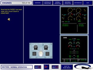
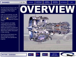
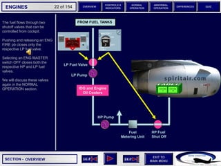
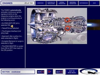
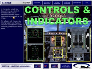
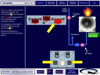
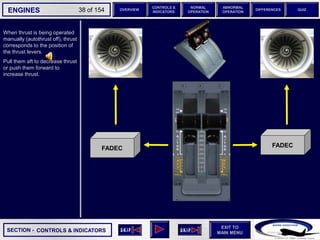
This document provides an overview of the engines on the Airbus A320 series aircraft. It describes the key components and systems, including the IAE V2500 high-bypass turbofan engines, Full Authority Digital Engine Control (FADEC), fuel system, and ignition system. It explains that the FADEC controls and monitors engine operation using EPR or N1 modes. It also discusses engine starts, idle settings, and protections provided during automatic starts on the ground.


![SECTION -
EXIT TO
MAIN MENU
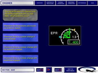
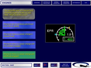
ENGINES OVERVIEW
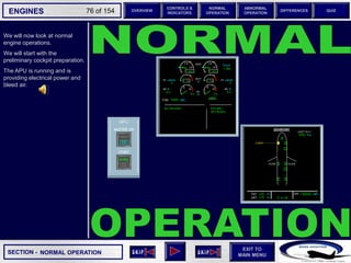
NORMAL
OPERATION
ABNORMAL
OPERATION
CONTROLS &
INDICATORS
DIFFERENCES QUIZ
74 of 154
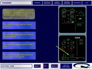
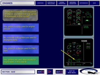
Start Valve
During engine start, the nacelle
temperature indications are
replaced by information
relating to ignition and start
valve operation.
The FADEC selected igniters
(A, B, or both [A &B] ) are
displayed when selected for
use.
The letter indicates that the
specific igniter, or igniters,
have been activated. It DOES
NOT indicate if they are
actually firing.
Start valve indications are
displayed below the igniters.
The start valves are displayed
either open or closed.
Below each start valve is a
digital indication of the bleed
pressure available to that start
valve.
The bleed pressure indication
is displayed in amber if the
minimum or maximum limits
are exceeded.
Valve Open
Valve Closed
CONTROLS & INDICATORS
FADEC selected igniter - indicates igniter is activated, NOT that the igniter is firing
Bleed Pressure
Green – normal
Amber – min or max pressure is exceeded](https://image.slidesharecdn.com/engines-230712094839-5fd7f2a0/85/Engines-ppt-74-320.jpg)