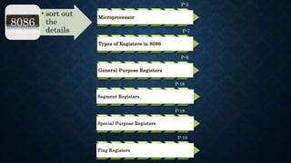
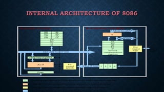
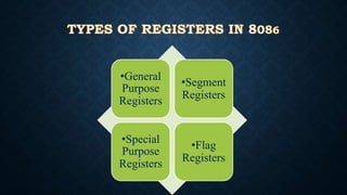
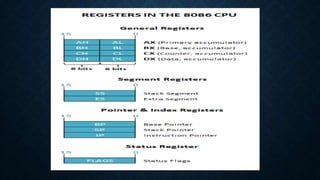
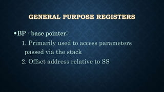
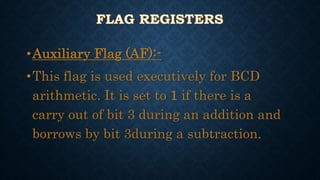
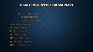
BISMILLAHIR RAHMANIR RAHIM
AS SALAMU
ALAYKUM
8086-MICROPROCESSOR
MD. GALIB HOSSAIN
ID-1436CSE00365
P-5
Microprocessor
P-7
Types of Registers in 8086
P-9
General Purpose Registers
P-16
Segment Registers
P-18
Special Purpose Registers
P-19
Flag Registers
•sort out
the
details
8086
• It is an integrated circuit, which contains all the functions
of the Central Processing Unit (CPU).
• It is not capable for handling the Boolean function.
• It contains only CPU, RAM, ROM, I/O, timer are
separately interfaced.
• Examples:-
INTEL 8086, INTEL Pentium series
INTERNAL ARCHITECTURE OF 8086
•General
Purpose
Registers
•Segment
Registers
•Special
Purpose
Registers
•Flag
Registers
• AX The Accumulator Register: (Divided into AH / AL)
• It consist of 8-bit registers AL and AH, when they
combine they used as 16-bit register.
• Generates shortest machine code
• Arithmetic, logic and data transfer
• One number must be AL or AX
• Multiplication and Division
• Input and Output
• BX - the base address register (divided into BH /
BL).
CX - the count register (divided into CH / CL):
1. Iterative code segments using the LOOP instruction
2. Repetitive operations on strings with the REP command
3. Count (in CL) of bits to shift and rotate
DX - the data register (divided into DH /
DL):
1. DX:AX concatenated into 32-bit
register for some MUL and DIV
operations
2. Specifying ports in some IN and OUT
operations
SI - source index register:
1. Can be used for pointer addressing of data
2. Used as source in some string processing
instructions
3. Offset address relative to DS
DI - destination index register:
1. Can be used for pointer addressing of data
2. Used as destination in some string
processing instructions
3. Offset address relative to ES
BP - base pointer:
1. Primarily used to access parameters
passed via the stack
2. Offset address relative to SS
SP - stack pointer:
1. Always points to top item on the stack
2. Offset address relative to SS
3. Always points to word (byte at even
address)
4. An empty stack will had SP = FFFEh
THERE ARE FOUR TYPES OF SEGMENT
REGISTERS:
•Code SegmentCS
•Data SegmentDS
•Extra SegmentES
•Stack SegmentSS
• CS - points at the segment containing the current
program.
• DS - generally points at segment where variables are
defined.
• ES - extra segment register, it's up to a coder to define
its usage.
• SS - points at the segment containing the stack.
• IP - the instruction pointer:
1. Always points to next instruction to be executed
2. Offset address relative to CS
• IP register always works together with CS segment
register and it points to currently executing
instruction
• Flags Register is modified automatically by
CPU after mathematical operations, this
allows to determine the type of the result, and
to determine conditions to transfer control to
other parts of the program
•Carry Flag (CF):-
•An addition causes this flag to be set to 1,
if there is carry out of the MSB, and
subtraction causes this to be set to 1 if
borrow is needed.
• Parity Flag (PF):-
• This is set to 1 if the low-order 8 bits of the
result of the previous operation contain an
even number of 1s. Otherwise it is reset to 0.
•Auxiliary Flag (AF):-
•This flag is used executively for BCD
arithmetic. It is set to 1 if there is a
carry out of bit 3 during an addition and
borrows by bit 3during a subtraction.
•Zero Flag (ZF):-
•This is set to 1 if the result of the
previous operation is zero and 0 if the
result of the previous operation is
non-zero.
• Sign Flag (SF):-
• This is set to 1 when result is negative. When
result is positive it is set to 0. Actually this
flag take the value of the most significant bit.
• Trap Flag (TF):-
• It is used for on chip debugging.
•Interrupt Enable Flag (IF):-
•When this flag is set to 1 CPU reacts
to interrupts from external devices.
• Direction Flag (DF) :-
• This flag is used by some instructions to
process data chains, when this flag is set to 0.
The processing is done forward, when this flag
is set to 1 the processing is done backward.
• Overflow Flag (OF):-
• This is set to 1 when there is a signed overflow.
• This indicates that the result is too large to fit in 8-bit
destination operand.
• The sum of two positive signed operands exceeds 127
• The difference of two negative operands is less than -128
• Example:
• When you add bytes 100 + 50 (result is not in range -
128...127).
1101 0111 1011 1001
+ 1101 0111 0111 1010
1010 1111 0011 0011
• In the above example:
• SF (Sign Flag) = 1
• ZF (Zero Flag) = 0
• PF (Parity Flag) =1
• CF (Carry Flag) =1
• AF (Auxiliary Flag) = 1
• OF (Overflow Flag) =1
0101 0110 0111 1110
- 0100 1110 1110 1010
0000 0111 1001 0100
• In the above example:
• SF (Sign Flag) = 0
• ZF (Zero Flag) = 0
• PF (Parity Flag) =0
• CF (Carry Flag) =0
• AF (Auxiliary Flag) = 0
• OF (Overflow Flag) =0
8086 Microprocessor

8086 Microprocessor

  • 1.
  • 2.
  • 3.
  • 4.
    P-5 Microprocessor P-7 Types of Registersin 8086 P-9 General Purpose Registers P-16 Segment Registers P-18 Special Purpose Registers P-19 Flag Registers •sort out the details 8086
  • 5.
    • It isan integrated circuit, which contains all the functions of the Central Processing Unit (CPU). • It is not capable for handling the Boolean function. • It contains only CPU, RAM, ROM, I/O, timer are separately interfaced. • Examples:- INTEL 8086, INTEL Pentium series
  • 6.
  • 7.
  • 9.
    • AX TheAccumulator Register: (Divided into AH / AL) • It consist of 8-bit registers AL and AH, when they combine they used as 16-bit register. • Generates shortest machine code • Arithmetic, logic and data transfer • One number must be AL or AX • Multiplication and Division • Input and Output
  • 10.
    • BX -the base address register (divided into BH / BL). CX - the count register (divided into CH / CL): 1. Iterative code segments using the LOOP instruction 2. Repetitive operations on strings with the REP command 3. Count (in CL) of bits to shift and rotate
  • 11.
    DX - thedata register (divided into DH / DL): 1. DX:AX concatenated into 32-bit register for some MUL and DIV operations 2. Specifying ports in some IN and OUT operations
  • 12.
    SI - sourceindex register: 1. Can be used for pointer addressing of data 2. Used as source in some string processing instructions 3. Offset address relative to DS
  • 13.
    DI - destinationindex register: 1. Can be used for pointer addressing of data 2. Used as destination in some string processing instructions 3. Offset address relative to ES
  • 14.
    BP - basepointer: 1. Primarily used to access parameters passed via the stack 2. Offset address relative to SS
  • 15.
    SP - stackpointer: 1. Always points to top item on the stack 2. Offset address relative to SS 3. Always points to word (byte at even address) 4. An empty stack will had SP = FFFEh
  • 16.
    THERE ARE FOURTYPES OF SEGMENT REGISTERS: •Code SegmentCS •Data SegmentDS •Extra SegmentES •Stack SegmentSS
  • 17.
    • CS -points at the segment containing the current program. • DS - generally points at segment where variables are defined. • ES - extra segment register, it's up to a coder to define its usage. • SS - points at the segment containing the stack.
  • 18.
    • IP -the instruction pointer: 1. Always points to next instruction to be executed 2. Offset address relative to CS • IP register always works together with CS segment register and it points to currently executing instruction
  • 19.
    • Flags Registeris modified automatically by CPU after mathematical operations, this allows to determine the type of the result, and to determine conditions to transfer control to other parts of the program
  • 20.
    •Carry Flag (CF):- •Anaddition causes this flag to be set to 1, if there is carry out of the MSB, and subtraction causes this to be set to 1 if borrow is needed.
  • 21.
    • Parity Flag(PF):- • This is set to 1 if the low-order 8 bits of the result of the previous operation contain an even number of 1s. Otherwise it is reset to 0.
  • 22.
    •Auxiliary Flag (AF):- •Thisflag is used executively for BCD arithmetic. It is set to 1 if there is a carry out of bit 3 during an addition and borrows by bit 3during a subtraction.
  • 23.
    •Zero Flag (ZF):- •Thisis set to 1 if the result of the previous operation is zero and 0 if the result of the previous operation is non-zero.
  • 24.
    • Sign Flag(SF):- • This is set to 1 when result is negative. When result is positive it is set to 0. Actually this flag take the value of the most significant bit. • Trap Flag (TF):- • It is used for on chip debugging.
  • 25.
    •Interrupt Enable Flag(IF):- •When this flag is set to 1 CPU reacts to interrupts from external devices.
  • 26.
    • Direction Flag(DF) :- • This flag is used by some instructions to process data chains, when this flag is set to 0. The processing is done forward, when this flag is set to 1 the processing is done backward.
  • 27.
    • Overflow Flag(OF):- • This is set to 1 when there is a signed overflow. • This indicates that the result is too large to fit in 8-bit destination operand. • The sum of two positive signed operands exceeds 127 • The difference of two negative operands is less than -128 • Example: • When you add bytes 100 + 50 (result is not in range - 128...127).
  • 28.
    1101 0111 10111001 + 1101 0111 0111 1010 1010 1111 0011 0011 • In the above example: • SF (Sign Flag) = 1 • ZF (Zero Flag) = 0 • PF (Parity Flag) =1 • CF (Carry Flag) =1 • AF (Auxiliary Flag) = 1 • OF (Overflow Flag) =1
  • 29.
    0101 0110 01111110 - 0100 1110 1110 1010 0000 0111 1001 0100 • In the above example: • SF (Sign Flag) = 0 • ZF (Zero Flag) = 0 • PF (Parity Flag) =0 • CF (Carry Flag) =0 • AF (Auxiliary Flag) = 0 • OF (Overflow Flag) =0