Download to read offline
![ELF Magnetic Field Mitigation by Active Shielding
COnCettina BuCCdk&Memher. IEEE, Mauro Feliziani, Member. IEEE. VhCenZO F u k
Dept. of Electrical Eng., Univ. of L'Aquila, Poggio di Roio, 67040 L'Aquila, Italy,
Abstrncr -- The reduction of extremely low frequency (ELF)
magnetic field in an area excited by power frequency currents is
investigated by active shielding techniques. The magnetic field
inside a shielded area is measured in simple test configurations.The
performances of the proposed field-controlled active shield are
showed.
1.lNTRODUCTlON
An interesting problem from a scientific and technical point
of view is that of reducing the magnetic field produced by a
power frequency source in a delimited region of space.
Often, especially in the immediate proximity of an
electromagnetic source, the magnetic field can be large
enough to violate some electromagnetic field exposure
standards or to degrade the functionality of electrical and
electronic systems. In this case it is necessary to reduce the
electromagnetic field strength to an acceptable level. In
general, two different techniques exist to attenuate the
surrounding magnetic fields: passive shielding and active
shielding.
The passive shielding is extensively used for protection
against high frequency fields. To shield static and extremely
low frequency (ELF) magnetic fields, materials such as
ferromagnetic shields and thick eddy-current shields can be
used [I]-[Ill. However, in the design of large volume
shielded enclosures, the ferromagnetic shield becomes too
heavy and too expensive for the amount of material needed,
while the eddy-current shield provides a very poor shielding
at low frequency.
Active shielding is an alternative attenuation method n
which the disturbing magnetic field can be reduced by
superposing other magnetic fields having about the same
magnitude, but in the opposite direction [5].The opposite
fields are generally produced by currents injected into
adequately designed active coils. The principal problem of
active shielding can be given by the high currents requested
in order to obtain a significant value of the shielding
effectiveness. Furthermore, active shielding works only at a
given frequency, normally at the power frequency, and there
is not any magnetic field attenuation at other frequencies:
higher order harmonic or radio frequency fields are not
attenuated.
The active shielding technique is here investigated.
Experimental results in test configurations are showed.
11. MATHEMATICAL MODEL
0-7803-7369-3/02/$17.0002002 IEEE
where Ar = r-Y'is the difference between the position vector
r o f the point of observation P and the position vector r'of
the element d / ' . From (2) it is possible to derive the
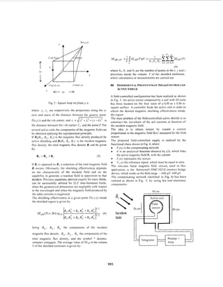
magnetic field produced by a square loop current. Assuming
the square loop of dimensions 2 a X 2b and parallel to the+
plane at a distance d, the coordinates of the loop four
corners are: C,(d, -b. -U), C2(d4,U ) , C,(d, h, a ) and C,(d, b.
-U) as shown in Fig. 2. The components ofthe magnetic flux
density produced by the active shielding, B,,,, B,,., and B,,,,
are given at generic point P(YJ,z) by [5]:
994
x - d
4
B(,j.=-Z(-l)'+'-P O I
B,, =-Z(-l);+'P o l -
rj(1.j +z;)4n ;=I
41r ;=I
.Y -d
4
(1; +y; )](https://image.slidesharecdn.com/activeshielding-150127052247-conversion-gate01/85/Active-shielding-1-320.jpg)


The document discusses techniques for mitigating extremely low frequency (ELF) magnetic fields using active shielding methods, particularly in environments with power frequency currents. It details the experimental setup, mathematical models, and effectiveness of the active shielding in reducing magnetic field exposure while highlighting its limitations at higher frequencies and the need for high currents. The proposed method showed a maximum attenuation of about 25 dB at 50 Hz, with a decrease at higher frequencies, and suggests future research directions including hybrid shielding techniques.


![[L2 Sambhav] Electro magnetic induction.pdf](https://cdn.slidesharecdn.com/ss_thumbnails/l2sambhavemi-231215223335-2720969b-thumbnail.jpg?width=640&height=640&fit=bounds)


