

Recommended
More Related Content
What's hot
What's hot (19)
Viewers also liked
Viewers also liked (10)
Similar to MICROWAVE ENGINEERING FUNDAMENTALS
Similar to MICROWAVE ENGINEERING FUNDAMENTALS (20)
Recently uploaded
Recently uploaded (20)
MICROWAVE ENGINEERING FUNDAMENTALS
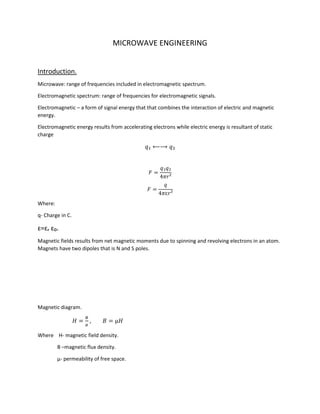
- 1. MICROWAVE ENGINEERING Introduction. Microwave: range of frequencies included in electromagnetic spectrum. Electromagnetic spectrum: range of frequencies for electromagnetic signals. Electromagnetic – a form of signal energy that that combines the interaction of electric and magnetic energy. Electromagnetic energy results from accelerating electrons while electric energy is resultant of static charge 𝑞₁ ⟵⟶ 𝑞₂ 𝐹 = 𝑞₁𝑞₂ 4𝜋𝑟² 𝐹 = 𝑞 4𝜋ɛ𝑟² Where: q- Charge in C. ɛ=ɛᵣ ɛ₀. Magnetic fields results from net magnetic moments due to spinning and revolving electrons in an atom. Magnets have two dipoles that is N and S poles. Magnetic diagram. 𝐻 = 𝐵 µ , 𝐵 = µ𝐻 Where H- magnetic field density. B –magnetic flux density. µ- permeability of free space.
- 2. When the two (magnetic and electric) are combined they give rise to electro-magnetism hence electromagnetic energy. Electromagnetic spectrum comprises the following signals or form of energy. Gamma rays. X-rays. Ultraviolet light (UV). Infrared. Microwave. Radio wave. Tabulate the EM spectrum. EM Freq. wavelength Energy Application Gamma rays 300 EHz 1 pm 1.24MeN Checking cracks in metals, building, railway tracks.. Hard X-rays 30EHz 10pm 124KeN -medicine (cancer) -Security –metal detectors. Microwave (EHF) 300GHz 1mm 1.24meV Communication –WiMAX, Radar, -imaging. Radio (ELF) 3Hz 100µm 12.4µeV -communication. -navigation. Table. Microwave spectrum. Initial bands. Freq. GHz wavelength Energy Application L 1-2 30-15 1800MHz GSM Microwave links, waveguide. S 2-4 15-7.5 2100MHz UMTS, WIFI, Bluetooth, Zigbee. C 4-8 7.5-3.8 satellite X 8-12 3.8-2.5 satellite Ku 12-18 2.5-1.7 satellite K 18-27 1.7-1.1 satellite Ka 27-40 1.1-0.75 V 40-75 0.75-0.4 W 75-110 0.4-0.27 Table. Microwave spectrum. E=hf
- 3. Where h-planks constant (6.62X10-38 Js). Application of microwave. GSM. Microwave links- waveguides. Satellite. Remote sensing. Microwave heating. Radar system. WLANS- Wi-Fi, Bluetooth, ZigBee, WiMAX. Differential equation. 1. Gauss’ law of electricity. ∇. 𝐸 = 𝑞 ɛ 2. Gauss law of magnetism. ∇. 𝐻 = 0 3. Faradays law ∇ × 𝐸 = − 𝜕𝐵 𝜕𝑡 4. Ampere/Maxwell law. ∇ × 𝐻=JC+JD= 𝜎𝐸 + 𝜕𝐷 𝜕𝑡 These equation expressed in free space. ∇. 𝐸 = 𝑞ₒ ɛₒ ∇. 𝐻 = 0 ∇ × 𝐸 = − 𝜕𝐵 𝜕𝑡
- 4. ∇ × 𝐻 = 𝜕𝐷 𝜕𝑡 Divergence. ∇= 𝛿 𝛿𝑥 + 𝛿 𝛿𝑦 + 𝛿 𝛿𝑧 Curl ∇× 𝐸 = | âₓ â𝑦 â𝑧 𝜕 𝜕𝑥 𝜕 𝜕𝑦 𝜕 𝜕𝑧 𝐸𝑥 𝐸𝑦 𝐸𝑧 | Determinant. =ậx( 𝜕𝐸𝑧 𝜕𝑦 − 𝜕𝐸𝑦 𝜕𝑧 )-ậy(( 𝜕𝐸𝑧 𝜕𝑥 ) − 𝜕𝐸𝑥 𝜕𝑧 )-ậz( 𝜕𝐸𝑦 𝜕𝑥 − 𝜕𝐸𝑥 𝜕𝑦 ) Example. Given. E=Emcos(ωt + βz) ∇× 𝐸 = | âₓ â𝑦 â𝑧 𝜕 𝜕𝑥 𝜕 𝜕𝑦 𝜕 𝜕𝑧 0 𝐸𝑦 0 | =ậx(0 − 𝜕𝐸𝑦 𝜕𝑧 ) =-ậx 𝜕𝐸𝑦 𝜕𝑧 =-ậx 𝜕𝐸𝑚𝑐𝑜𝑠(𝜔𝑡+𝛽𝑧) 𝜕𝑧 = 𝛽Em sin(ωt + βz) ậx But ∇ × 𝐸 = − 𝜕𝐵 𝜕𝑡
- 5. ∫ − 𝜕𝐵 𝜕𝑡 = ∫ βEmsin(ωt + βz)ậx B= 𝛽 𝜔 Emcos(ωt + βz)ậx TESLA. D=ɛO E =ɛO Emcos(ωt + βz) 𝐶 𝑀² H= 𝐵 µ = 𝛽 𝜔µ Emcos(ωt + βz) ậx 𝐴 𝑀 . Impedance. Z= 𝐸 𝐻 .𝜴 = 𝜔µ 𝛽 𝜴. Appling the same theorem, find B, E and D. given. H=HM 𝑒(𝜔𝑡−𝛽𝑧) ậx . Exercise. Given H=20𝑒 𝑗(109 𝑡+𝛽𝑧) ậy 𝑚𝐴 𝑀 . Determine D, H, and B then draw the waveform. For the analysis above obtain the actual values in the microwave range. (Microwave range 300MHz- 300GHz), but 1-10GHz are commonly used.
- 6. Electromagnetic wave analysis based on Maxwell’s equation in time varying form in space. ∇ × 𝐸 = −𝑗𝜔µ𝐻 ∇ × 𝐻 = 𝜎𝐸 + 𝑗𝜔ɛ𝐸 ∇. 𝐵 = 0 ∇. 𝐷 = 0 Where: B=µH, J= 𝜎E, D=ɛE. Taking the curl of both expressions. The curl of E. ∇ × (∇ × 𝐸) = −𝑗𝜔µ(𝛻 × 𝐻) = −𝑗𝜔µ(𝜎𝐸 + 𝑗𝜔ɛ𝐸) From curl identity, this can expressed as, 𝛻2 𝐸 = 𝑗𝜔µ(𝜎𝐸 + 𝑗𝜔ɛ𝐸) = 𝑗𝜔µ(𝜎 + 𝑗𝜔ɛ)𝐸 The curl of H. ∇ × (∇ × 𝐸) = 𝛻 × (𝜎𝐸 + 𝑗𝜔ɛ𝐸) = 𝜎𝛻 × 𝐸 + 𝑗𝜔ɛ𝛻 × 𝐸 𝛻2 𝐻 = 𝜎(−𝑗𝜔µ𝐻) + 𝑗𝜔ɛ(−𝑗𝜔µ𝐻) = 𝑗𝜔µ(𝜎 + 𝑗𝜔ɛ)𝐻 By taking, =𝛻, where 𝛶-gamma. We have. Υ2 𝐻 = 𝑗𝜔µ(𝜎 + 𝑗𝜔ɛ)𝐻 Υ2 = 𝑗𝜔µ(𝜎 + 𝑗𝜔ɛ) 𝛶 = √(𝑗𝜔µ(𝜎 + 𝑗𝜔ɛ)) Or 𝛶2 𝐸 = 𝑗𝜔µ(𝜎 + 𝑗𝜔ɛ)𝐸 𝛶2 = 𝑗𝜔µ(𝜎 + 𝑗𝜔ɛ) 𝛶 = √(𝑗𝜔µ(𝜎 + 𝑗𝜔ɛ)) 𝛶 = 𝛼 + 𝑗𝛽
- 7. 𝛼 = 𝜔√( µɛ 2 ((√1 + ( 𝜎 𝜔ɛ ) 2 ) − 1) 𝛽 = 𝜔√( µɛ 2 √𝐻 ( 𝜎 𝜔ɛ ) ² + 1) The above equation are for partially medium. Perfect dielectric For a perfect dielectric. 𝜎=0, 𝛼=0, 𝛽=𝜔√µ𝜔 Perfect conductor. For a perfect conductor. 𝜎 >>𝜔ɛ. Which can be expressed as ( 𝜎 𝜔ɛ ) ² >> 1. 𝛼 = 𝛽 = 𝜔√( µɛ 2 . 𝜎 𝜔ɛ ) = 𝜔√ µ𝜎 2𝜔 = √ 𝜔µ𝜎 2 But 𝜔=2𝜋f. Therefore. = √𝜋𝑓µ𝜎 Skin depth of a conductor, which is how far can signal penetrate into a conductor, is expressed in the form. 𝛿 = 1 𝛽 = 1 √𝜋𝑓µ𝜎
- 8. Exercise. Determine the microwave skin depth of a waveguide F=10GHz, µr=2 (Cu, Al, Fe). Also find the mostly used material for waveguides and why. Effects on EM as they propagate through media. Reflection Refraction Attenuation Scattering Diffraction Absorption Depolarization Fading Losses Dispersion Reflection. Bouncing back when they are in contact with an obstacle. In free space this can be buildings, vehicles, flying objects, mountains etc. in waveguide transmission is done by reflection, metallic objects are mostly used because are considered perfect reflectors. Obeys laws of reflection, depends on µ and ɛ but mostly permittivity. Related by: sin 𝜃₁ sin 𝜃₂ = √( ɛ₂µ₂ ɛ₁µ₁ ) For free space, (air) µ₁=µ₂=1 Refraction. This bending of waves during propagation as they travel from one medium to the other. Obeys Snell’s law. 𝑛₁ sin 𝜃₁ = 𝑛₂ sin 𝜃₂ Where n1 and n2 are the refractive indexes. Refractive index, n, depends on the permittivity of the medium. In waveguides different air density can affect the signal. Fiber as a waveguide has material with different n.
- 9. Attenuation. Process when the wave losses power/energy as it propagates. Depends on attenuation constants, which also depends on material type/medium. 𝛶 = 𝛼 + 𝑗𝛽 ↕ E=EM 𝑒 𝛶𝑡+𝑗𝜔𝑧 =EM 𝑒 𝑗(𝛶𝑡+𝛽𝑧) where 𝛶=j𝛽 =EMcos(𝜔𝑡 + 𝛽𝑧) 𝑜𝑟 E=EMsin(𝜔𝑡 + 𝛽𝑧) Affected by frequency. Scattering Reflection from non-uniform surfaces. In contact with particles with wavelength close to the surface/object size. In wave guides it can be caused by minute particles and irregular surface. Diffraction. When the waves comes into contact with a sharp object/edge. It’s observed at the ends of the waveguides. Diagram. Depends on the waveguides of the EM wave. Dispersion. Signal/wave spreads as it propagates making the signal weaker or cancellation sometime signal addition. Depolarization Polarization orientation of the EM wave. There are three types Linear (vertical and horizontal ) Circular Elliptical Depolarization- change of alignment vertical to horizontal or viceversa.in waveguide, its cause variation of ionization level due to density variation. Absorption.
- 10. Transfer of energy to obstacles or medium material resulting in change to other form of energy e.g. heat. Exercise: discuss the difference between absorption and attenuation. Fading Reduction of signal strength due to variations as it propagates. Losses. Free space losses. Feeder losses due to misalignment. Obstacle losses. Passive microwave devices. Passive devices do not require external power source to operate e.g. resistor. Do not increase the strength of the signal. Most waveguides are in this category. A waveguide is a device that directs an EM wave through it as it move from source to destination. EM waves directed includes: TEM- Transverse Electric and Magnetic wave TE -Transverse Electric wave TM- Transverse magnetic wave. TEM. Has both magnetic and electric properties as components of the wave being propagated. TE- has electric energy only. TM. Has the magnetic energy only. The wave results in different modes of propagation through the waveguides. They can be analyzed and determined using Maxwell’s equations. The equation are given by: Faradays’ law of magnetism and Amperes’ law of electricity. Using Faraday’s law. Note all equation are in vector form. ∇ × 𝐸 = −𝑗𝜔µ𝐻 ∇× 𝐸 = | âₓ â𝑦 â𝑧 𝜕 𝜕𝑥 𝜕 𝜕𝑦 𝜕 𝜕𝑧 𝐸𝑥 𝐸𝑦 𝐸𝑧 |=−𝑗𝜔µ𝐻 ậx:( 𝜕𝐸𝑧 𝜕𝑦 − 𝜕𝐸𝑦 𝜕𝑧 ) = −𝑗𝜔µ𝐻x ậy:( 𝜕𝐸𝑥 𝜕𝑥 − 𝜕𝐸𝑧 𝜕𝑧 )=𝑗𝜔µ𝐻y
- 11. ậz:( 𝜕𝐸𝑦 𝜕𝑥 − 𝜕𝐸𝑥 𝜕𝑦 ) =−𝑗𝜔µ𝐻z Taking the waveform in z-direction to be given by 𝑒−𝑗𝐵𝑍 and substituting in the above equation. ậx.( 𝜕𝐸𝑧 𝜕𝑦 − 𝜕𝐸𝑦 𝜕𝑧 ) = −𝑗𝜔µ𝐻x −𝑗𝜔µ𝐻x = 𝜕𝐸𝑧 𝜕𝑦 + 𝑗𝐵𝐸y 𝑗𝜔µ𝐻y = 𝜕𝐸𝑧 𝜕𝑧 + 𝑗𝐵𝐸x ậz:( 𝜕𝐸𝑦 𝜕𝑥 − 𝜕𝐸𝑥 𝜕𝑦 ) =−𝑗𝜔µ𝐻z Using Amperes equation. ∇ × Ĥ = 𝑗𝜔µ𝐻 ∇× 𝐻 = | âₓ â𝑦 â𝑧 𝜕 𝜕𝑥 𝜕 𝜕𝑦 𝜕 𝜕𝑧 𝐻𝑥 𝐻𝑦 𝐻𝑧 |=𝑗𝜔ɛ𝐸 ậx :( 𝜕𝐻𝑧 𝜕𝑦 − 𝜕𝐻𝑦 𝜕𝑧 ) = 𝑗𝜔µ𝐸x 𝜕𝐻𝑧 𝜕𝑦 − 𝜕𝑒−𝑗𝐵𝑍 𝜕𝑧 = 𝑗𝜔µ𝐸x 𝜕𝐻𝑧 𝜕𝑦 + 𝑗𝐵𝐻y= 𝑗𝜔µ𝐸x ậy :( 𝜕𝐻𝑧 𝜕𝑥 − 𝜕𝐻𝑥 𝜕𝑧 )=𝑗𝜔µ𝐸y 𝜕𝑒−𝑗𝐵𝑍 𝜕𝑥 − 𝜕𝐻𝑥 𝜕𝑧 = 𝑗𝜔µ𝐸y = 𝜕𝐻𝑧 𝜕𝑧 + 𝑗𝐵Hx ậz :( 𝜕𝐻𝑦 𝜕𝑥 − 𝜕𝐻𝑥 𝜕𝑦 ) =𝑗𝜔µ𝐸z Manipulating the above equation. We can get the transverse components of Ē and Ĥ, i.e. the x and y components. Taking the first expression and making Hx the subject of the formula we obtain.
- 12. Hx =− ( 𝜕𝐸𝑧 𝜕𝑦 +𝑗𝐵𝐸y 𝑗𝜔µ ) = 𝑗 𝜔µ ( 𝜕𝐸𝑧 𝜕𝑦 + 𝑗𝐵𝐸y) = 𝑗 𝜔µ 𝜕𝐸𝑧 𝜕𝑦 − 𝐵𝐸y 𝜔µ But. Ey= 𝜕𝐻𝑧 𝜕𝑥 + 𝛽 𝜔ɛ Hx Therefore. Hx= 𝑗 𝜔µ 𝜕𝐸𝑧 𝜕𝑦 − 𝐵 𝜔2µ 𝜕𝐻𝑧 𝜕𝑥 + 𝛽² 𝜔²µɛ Hx = ( 𝑗 𝜔µ 𝜕𝐸𝑧 𝜕𝑦 − 𝐵 𝜔2µ 𝜕𝐻𝑧 𝜕𝑥 ) 1− 𝛽² 𝜔²µɛ Let, 𝜔²µɛ= k² Hx = 𝑗 k²−β² (𝜔ɛ 𝜕𝐸𝑧 𝜕𝑦 − 𝛽 𝜕𝐻𝑧 𝜕𝑥 ) And kC²= k²-𝛽² Using the same procedure obtain: Hy, Ex and Ey Hy =− 𝑗 kc² ( 𝜔ɛ 𝜕𝐸𝑧 𝜕𝑥 + 𝛽 𝜕𝐻𝑧 𝜕𝑦 ) Ex =− 𝑗 kc² ( 𝛽 𝜕𝐸𝑧 𝜕𝑥 + 𝜔µ 𝜕𝐻𝑧 𝜕𝑦 ) Ey = 𝑗 kc² (−𝛽 𝜕𝐸𝑧 𝜕𝑦 + 𝜔µ 𝜕𝐻𝑧 𝜕𝑥 ) All the above equation are TEM such that the electric and magnetic exist in z-direction, thus longitudinal with the direction of propagation and therefore both of them exist i.e. EZ and HZ. Modes TE Mode.
- 13. Transverse electric: indicates that electric field is cross with direction of propagation hence EZ=0 but HZ≠0. The above expressions becomes: Hx = 𝑗 kc² (−𝛽 𝜕𝐻𝑧 𝜕𝑥 ) Hx =− 𝑗 kc² 𝛽 𝜕𝐻𝑧 𝜕𝑥 Ex =− 𝑗 kc² ( 𝜔µ 𝜕𝐻𝑧 𝜕𝑦 ) =− 𝑗 kc² 𝜔µ 𝜕𝐻𝑧 𝜕𝑦 Ey = 𝑗 kc² ( 𝜔µ 𝜕𝐻𝑧 𝜕𝑥 ) = 𝑗 kc2 𝜔µ 𝜕𝐻𝑧 𝜕𝑥 Hy =− 𝑗 kc² 𝛽 𝜕𝐻𝑧 𝜕𝑦 TM Mode. Transverse magnetic: the magnetic fields is cross to the direction of propagation, hence EZ≠0 but HZ=0. The above expression becomes. Hx = 𝑗 kc² 𝜔ɛ 𝜕𝐸𝑧 𝜕𝑦 Hy =− 𝑗 kc² 𝜔ɛ 𝜕𝐸𝑧 𝜕𝑥 Ex =− 𝑗 kc² 𝛽 𝜕𝐸𝑧 𝜕𝑥 Ey =− 𝑗 kc² 𝛽 𝜕𝐸𝑧 𝜕𝑦 TEM Mode The E and H are both transverse i.e. perpendicular to the direction of propagation, both EZ and HZ are zero. HX, HY, EX and Ey do not exist.
- 14. The waveguides that can propagate TEM should have two lines for instance coaxial, microstrip and coplanar. Types of waveguides. There are several types classified according to the following features. Number of lines. Material –conductor, dielectric. Types of modes of propagation TE, TM, TEM, and hybrid. Cut of frequency. Shape: Rectangular, Cylindrical and Elliptical. Material type. Level of permittivity. Technology. Based on the above, the types includes: Metallic waveguides. Metallic TEM and quasi TEM. Dielectric. Metallic waveguides. Are constructed from metallic material, are in different shapes including: 1. Rectangular. Supports TE and TM but not TEM. It’s has a cut off frequency. 2. Cylindrical. The face is circular with a given length, radius is the main consideration in its design. R Diagram. Supports TE and TM. 3. Elliptical. Width
- 15. Diagram. Supports TE and TM. Quasi TEM. Have more than a single line. Includes: Coaxial, Strip-line Coaxial rectangular. Coaxial. Inner core. Outer conductor insulator Diagram It has an inner core, conductor that is insulated and separated from the outer conductor. At the top there is an insulator referred as outer jacket. The two radii, inner and outer radii, are considered is its design. Coaxial rectangular. Has rectangular dimensions.
- 16. Inner core. Outer conductor dielectric Diagram. Strip-line Construction. Ground w b ɛᵣ Strip-line Diagram. Constructed by etching a conductor with width of W on a dielectric material with ɛr in the middle of the dielectric as shown above. The most important parameter are the width of the conductor (w) and the height of the dielectric (b). The conductor appears at 𝑏 2 distance from either side upper or lower. This parameter b and w will directly affect the capacitive and inductive properties of the line which together with ɛr also affects the plane, group velocities, propagation constant and the impedance of the device. Vg = 𝑐 √ɛᵣ c- Velocity of light. The fields will appear as follows.
- 17. Diagram. It supports TEM mode. Other lines include. Slot lone Coplanar. Microstrip. Microstrip line. microstrip Diagram. Constructed by etching a conductor at the top of a dielectric material with a ground running across the bottom of the dielectric. The important parameter include w-width of the line, b the separation between the ground and the line and the dielectric material constant ɛr. These will affect capacitive and inductive properties as well as vp, vg, 𝜂 and 𝛽. The fields are given by Diagram. Impedance matching two port network. NW 2 NW 1 High impedance Low impedance Connecting in this form causes reflection of signal, it should be connected as below.
- 18. NW 2 NW 1 High impedance Low impedance Transistor can be used for impedance matching. Covered microstrip. Similar to the microstrip the difference being that strip is covered. Cover (dielectric material) microstrip Diagram. The cover has an effect which can be negative in that it can introduce losses. Slot line. Construction. Slot line Diagram. Constructed by etching a metallic material at the top of the dielectric creating a section without the conductor, this forms the slot. Coplanar.
- 19. Construction. Has two slots. Diagram. Obtained by etching two sessions on a metal conductor then coating done on dielectric. Additional devices. Ridge waveguides. Dielectric waveguides. i) Fiber waveguide. ii) Plain dielectric. Ridge waveguide. Ridges are developed by a dielectric material. Ridges (ɛᵣ₁ ) Diagram Ridges are developed on a dielectric material. Fiber waveguide. Construction. ɛ₂ ɛ₁
- 20. Diagram. It developed from two materials with different dielectric properties. Reflection and refraction can be principles can be applied in their applications. Plain dielectric. ɛᵣ Diagram. Developed using single material type with specific dielectric properties. Supports TE and TM. Active Microwave devices. Require power to operate and can increase the strength of a signal actually includes electronics devices semiconductor, Diodes, Transistors, Integrated circuits. Diodes. Types:- Schotty diode. PIN diode. Tunnel diode. Transistors include BJT, FETs. Integrated circuits includes: BJT based technology FET based technology. Others are; semiconductor resistor and capacitor. Exercise. 1. Derive the cut-off frequency for all the above waveguides discussed. Obtain: vp, vg, impedance (𝜂), propagation constant (𝛽), for all the waveguide above.
- 21. 2. Discuss the different active microwave devices. Discussion should include: definition, symbol, construction, features, operation and applications. 3. Do the same for passive microwave devices.