This paper presents the analysis, design, and optimization of multilayer antennas using the wave concept iterative process (WCIP), highlighting its effectiveness in characterizing patch antennas and multilayer circuits. The study demonstrates high computational speed achieved through fast modal transform and verifies the convergence of the method through simulation results. Key findings include resonance frequencies of the multilayer structure and the efficiency of WCIP for analyzing electromagnetic wave transmission in these circuits.
![Bulletin of Electrical Engineering and Informatics
ISSN: 2302-9285
Vol. 6, No. 3, September 2017, pp. 265~270, DOI: 10.11591/eei.v6i3.621 265
Received June 8, 2017; Revised August 16, 2017; Accepted August 30, 2017
Analysis, Design and Optimization of Multilayer
Antenna Using Wave Concept Iterative Proces
Amri Houda*
Mohamed Cherif Messaadia University, Souk Ahras, Algeria
Actives Devices and Materials Laboratory, Larbi Ben M’Hidi University, Oum El Bouaghie, Algeria
*Coressponding author, e-mail: amrihouda@gmail.com
Abstract
The wave concept iterative process is a procedure used for analyses a planar circuits This
method consists in generating a recursive relationship between a wave source and reflected waves from
the discontinuity plane which is divided into cells. A high computational speed has been achieved by using
Fast Modal Transform (FMT). In this paper we study a patch antenna and multilayer circuits, to determine
the electromagnetic characteristics of these structures.
Keywords: WCIP, planar circuit, patch antenna, multilayer circuit, FMT
1. Introduction
Antennas are a very important component of communication systems. By definition, an
antenna is a device used to transform an RF signal, traveling on a conductor, into an
electromagnetic wave in free space. Antennas demonstrate a property known as reciprocity,
which means that an antenna will maintain the same characteristics regardless if it is
transmitting or receiving. Most antennas are resonant devices, which operate efficiently over a
relatively narrow frequency band. An antenna must be tuned to the same frequency band of the
radio system to which it is connected; otherwise the reception and the transmission will be
impaired. When a signal is fed into an antenna, the antenna will emit radiation distributed in
space in a certain way.
2. The Theoretical Basis
2.1. Definition of the WCIP
WCIP method is based on full wave transverse wave formulation and the collection at
the interfaces. A multiple reflection procedure is started using initial conditions and stopped
once convergence is archived. Two operators relating incident waves and scattered waves in
the spatial domain and in the spectral domain governs the scattering operator ̂ and the
reflection operator ̂ .
Figure 1. The process Iterative [1]](https://image.slidesharecdn.com/07621-210608030852/85/Analysis-Design-and-Optimization-of-Multilayer-Antenna-Using-Wave-Concept-Iterative-Process-1-320.jpg)
![Bulletin of Electrical Engineering and Informatics
ISSN: 2302-9285
Vol. 6, No. 3, September 2017, pp. 265~270, DOI: 10.11591/eei.v6i3.621 265
Received June 8, 2017; Revised August 16, 2017; Accepted August 30, 2017
Analysis, Design and Optimization of Multilayer
Antenna Using Wave Concept Iterative Proces
Amri Houda*
Mohamed Cherif Messaadia University, Souk Ahras, Algeria
Actives Devices and Materials Laboratory, Larbi Ben M’Hidi University, Oum El Bouaghie, Algeria
*Coressponding author, e-mail: amrihouda@gmail.com
Abstract
The wave concept iterative process is a procedure used for analyses a planar circuits This
method consists in generating a recursive relationship between a wave source and reflected waves from
the discontinuity plane which is divided into cells. A high computational speed has been achieved by using
Fast Modal Transform (FMT). In this paper we study a patch antenna and multilayer circuits, to determine
the electromagnetic characteristics of these structures.
Keywords: WCIP, planar circuit, patch antenna, multilayer circuit, FMT
1. Introduction
Antennas are a very important component of communication systems. By definition, an
antenna is a device used to transform an RF signal, traveling on a conductor, into an
electromagnetic wave in free space. Antennas demonstrate a property known as reciprocity,
which means that an antenna will maintain the same characteristics regardless if it is
transmitting or receiving. Most antennas are resonant devices, which operate efficiently over a
relatively narrow frequency band. An antenna must be tuned to the same frequency band of the
radio system to which it is connected; otherwise the reception and the transmission will be
impaired. When a signal is fed into an antenna, the antenna will emit radiation distributed in
space in a certain way.
2. The Theoretical Basis
2.1. Definition of the WCIP
WCIP method is based on full wave transverse wave formulation and the collection at
the interfaces. A multiple reflection procedure is started using initial conditions and stopped
once convergence is archived. Two operators relating incident waves and scattered waves in
the spatial domain and in the spectral domain governs the scattering operator ̂ and the
reflection operator ̂ .
Figure 1. The process Iterative [1]](https://image.slidesharecdn.com/07621-210608030852/75/Analysis-Design-and-Optimization-of-Multilayer-Antenna-Using-Wave-Concept-Iterative-Process-1-2048.jpg)
![ ISSN: 2302-9285
Bulletin of EEI Vol. 6, No. 3, September 2017 : 265 – 270
266
The wave concept iterative process WCIP is defined as [2-3].
A
B
A
B
S
A
ˆ
ˆ
0
(1)
Where the incident waves A
and the scatered waves B
are calculated from the tangentiel
electric and magnetic fields E
and H
:
i
i
i
i
i
i
i
i
i
i
J
Z
E
Z
B
J
Z
E
Z
A
0
0
0
0
2
1
2
1
(2)
where: i
Z0 is the characteristic impedance of the same medium
i indicates the medium 1or 2
i
i H
n
J
is the density of courant
2.2. The Reflection Operator ̂
The reflection operator is deduced from the admittance operator and the wave’s
definition in (3)
mn
mn
mn
i
mn
i
mn
mn f
Y
Z
Y
Z
f
0
0
1
1
(3)
r
mn
r
r
TM
mn
r
mn
r
TE
mn
j
Y
j
Y
0
0
(4)
2.3. The Scattering (Diffraction) Operator ̂
The scattering operator ̂ is deduced from the equivalent circuit on each sub domain of
the interface S. the boundary conditions is expressed for fields in the next equation:
source
on the
0
isolante
on the
0
and
0
metal
on the
0
2
1
0
0
1
2
1
2
1
2
1
J
J
Z
E
E
J
J
E
E
E
E
Moreover, since operators ( ̂ and Ŝ ) are defined in both the space and the spectral
domains, the iterative process implies switching between these domains, which is ensured by
the fast mode transform (FMT) and its inverse.
2.4. Definition of Fast Modal Transformation FMT in Periodic Wave Guide
The classic 2D Fast Fourier Transformation of the waves Aix,Aiy is defined as following:](https://image.slidesharecdn.com/07621-210608030852/85/Analysis-Design-and-Optimization-of-Multilayer-Antenna-Using-Wave-Concept-Iterative-Process-2-320.jpg)
![Bulletin of EEI ISSN: 2302-9285
Analysis, Design and Optimization of Multilayer Antenna Using Wave Concept... (Amri Houda)
267
b
m
a
m
e
e
A
y
x
A
e
e
A
y
x
A
ym
xm
mn
y
j
x
j
ymn
y
mn
y
j
x
j
xmn
x
ny
xm
ny
xm
2
2
,
,
(5)
Where
b
m
a
m
ym
xm
2
2
are the Fourier coefficients
We project the vectors A(x, y) in the complete set of modes corresponding to
rectangular periodic wave guide
f .
mn
TM
y
mn
TM
ymn
mn
TE
y
mn
TE
ymn
y
mn
TM
x
mn
TM
xmn
mn
TE
x
mn
TE
xmn
x
f
A
f
A
y
x
A
f
A
f
A
y
x
A
,
,
,
,
,
,
(6)
Projecting the equation (6) in the set of modes, we can deduce [4]:
y
x
A
f
y
x
A
f
A
y
x
A
f
y
x
A
f
A
y
TM
y
mn
x
TM
x
mn
mn
TM
mn
y
TE
y
mn
x
TE
x
mn
mn
TE
mn
,
,
,
,
,
,
,
,
(7)
The multilayered structure can be modulated by an equivalent circuit illustrated in Figure 2
The two network port represents the dielectric between the conductor in the planes and .
: is the admittance of upper metal box in the plan
: is the admittance of low metal box in the plan
According to Figure 2 it is possible to establish the following equations
Figure 2. Equivalent circuit](https://image.slidesharecdn.com/07621-210608030852/85/Analysis-Design-and-Optimization-of-Multilayer-Antenna-Using-Wave-Concept-Iterative-Process-3-320.jpg)
![ ISSN: 2302-9285
Bulletin of EEI Vol. 6, No. 3, September 2017 : 265 – 270
268
Space domain:
03
'
02
3
'
2
23
3
'
2
02
01
2
1
12
2
1
A
A
B
B
S
A
A
A
A
B
B
S
A
A
(8)
and have the same experience a ̂
Spectral domain:
'
2
2
'
2
2
3
1
3
1
3
1
0
0
A
A
B
B
A
A
B
B
Q
(9)
3
1
,
: reflected operator in the spectral domain
Q
: is the admittance operator of network port
The Q two ports network can be characterized by referring to the theory of the
transmission lines [5].
3. Modelisation and Results
The new formulation of the iterative method is applied to two different structures: a
patch antenna and multilayered structure.
3.1. Simulation of Patch Antenna
The proposed approach is first checked by considering the structure given in Figure 3.
This structure consists of a patch antenna connected to a microstrip line section. The box size is
35*64 mm. The substrate characteristics are ε=4.78 with a thickness of 0.79 mm. The line is 20
mm long and 2.34 mm wide, and the patch is 0.11387 mm wide and 1.5 mm long. Here, the
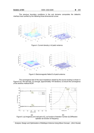
patch is simulated using an iterative method. First, verified the convergence of the method
(Figure 6(a)). The patch must be 1.5 mm long and the excitation frequency is f=19.6 GHz. The
results of frequency simulation have printed in the Figure 6(b).
Figure 3. The electromagnetic structure
0 5 10 15 20 25 30 35
0
5
10
15
20
25
30
35](https://image.slidesharecdn.com/07621-210608030852/85/Analysis-Design-and-Optimization-of-Multilayer-Antenna-Using-Wave-Concept-Iterative-Process-4-320.jpg)
![ ISSN: 2302-9285
Bulletin of EEI Vol. 6, No. 3, September 2017 : 265 – 270
270
3.2. Simulation of Multilayer Structure
The second study is the electromagnetic multilayer structure, when the two dielectric
interfaces consist of a patch antenna connected to a micro strip line section. The substrates
characteristics are epsr1=4.78 with a thickness of 0.79 mm. and epsr2=9.87 with a thickness of
0.5mm.
(a) (b)
Figure 7. The diffraction operator as function of frequency (a) The transmmision coefficient (b)
The reflection coefficient
The resonance frequencies of electromagnetic structure as shown in the previous figure.
Theses resonance frequencies are 9–10–10.5GHz.
The resonance box : f=4GHz
The resonance is periodic; it is repeated after 10GHz.
The wavelength is 30< λres<35mm
4. Conclusion
This paper is performed the transmission of electromagnetic waves on the multilayer
antenna, and confirms that the WCIP method is also highly flexible and efficient for this type of
circuits.
References
[1] Azizi (M), Aubert (H), Bandrand (H). A New Iterative Method for Scattering Problems. In European
microwave conf., proc, 1995; 1: 255-258J.
[2] Gharsallah (A), Gharbi (A), Desclos (L), Baudrand (H), Analysis of Interdigital Capacitor and Quasi-
lumped Miniaturized filters Using Iterative Method. Int. J. Numer. Mode l. 2002; 15: 169–179.
[3] Mami (A), Zairi (H), Gharsallah (A), Baudrand (H). Analysis of Micro-strip Spiral Induct or by Using
Iterative Method, Microw. Opt. Technol. Lett. 2002; 35(4): 302–306,
[4] Gharsallah (A), Gharbi (A), Baudrand (H). Efficient Analysis of Multipon Pasrive Circuits Using the
Iterative Technique Electromagnetics. Microw. Opt.Technol. Lett. 2001; 21: 75-84.
[5] Kaddour (M), Mami (A), Gharsallah (A), Gharbi (A), Baudrand (H). Analysis of Multilayer Microstrip
Antennas by Using Iterative Method. Journal of Microwaves and Optoelectronics. April 2003; 3(1): 39-
52.
0 5 10 15
x 10
10
0.72
0.74
0.76
0.78
0.8
0.82
0.84
0.86
X: 1.05e+011
Y: 0.7879
X: 9.5e+010
Y: 0.788
X: 1e+011
Y: 0.8012
X: 1e+011
Y: 0.7371
X: 1.05e+011
Y: 0.721
Frequency (Hz)
The
transmission
coefficient
(db)
X: 9.5e+010
Y: 0.7211
S12
S21
0 5 10 15
x 10
10
0.2
0.25
0.3
0.35
0.4
0.45
0.5
X: 9.5e+010
Y: 0.4593
X: 1e+011
Y: 0.4387
X: 1.05e+011
Y: 0.4605
X: 1e+011
Y: 0.2633
X: 9.5e+010
Y: 0.2797
X: 1.05e+011
Y: 0.2805
Frequency (Hz)
The
reflexion
coefficient
(db)
S11
S21](https://image.slidesharecdn.com/07621-210608030852/85/Analysis-Design-and-Optimization-of-Multilayer-Antenna-Using-Wave-Concept-Iterative-Process-6-320.jpg)


![Chapter 7 answers_to_examination_style_questions[1]](https://cdn.slidesharecdn.com/ss_thumbnails/chapter7answerstoexaminationstylequestions1-140110145417-phpapp02-thumbnail.jpg?width=640&height=640&fit=bounds)