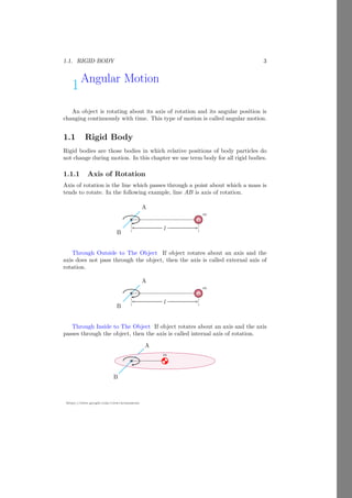
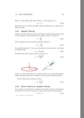
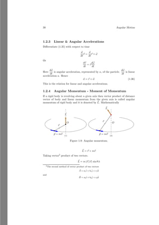
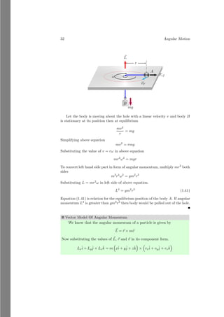
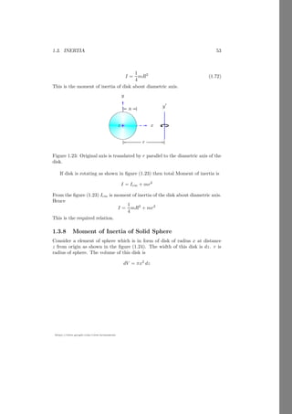
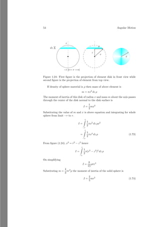
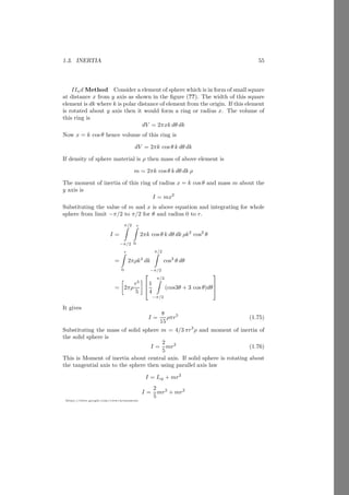
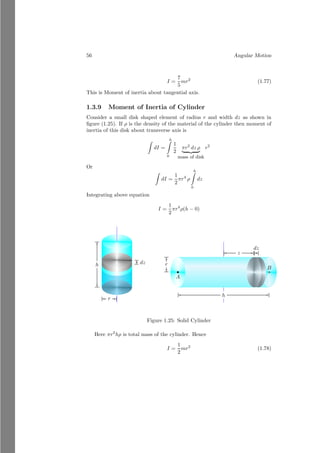
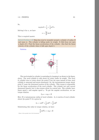
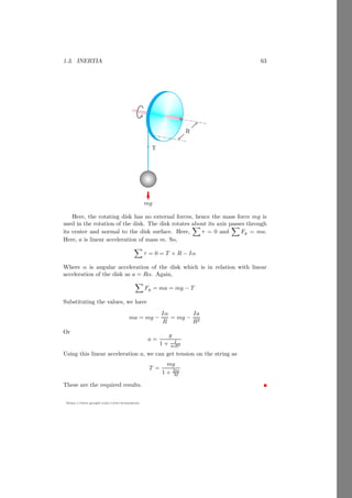
1
ANGULAR MOTION
AN INTRODUCTION
Arun Umrao
https://sites.google.com/view/arunumrao
DRAFT COPY - GPL LICENSING
2 Angular Motion
Contents
1 Angular Motion 3
1.1 Rigid Body . . . . . . . . . . . . . . . . . . . . . . . . . . . . . . 3
1.1.1 Axis of Rotation . . . . . . . . . . . . . . . . . . . . . . . 3
1.1.2 Moment of Force . . . . . . . . . . . . . . . . . . . . . . . 4
1.1.3 Equilibrium & Stability . . . . . . . . . . . . . . . . . . . 7
1.1.4 Equilibrium Point . . . . . . . . . . . . . . . . . . . . . . 8
1.1.5 Equilibrium of Moment of Force . . . . . . . . . . . . . . 9
1.1.6 Center of Mass . . . . . . . . . . . . . . . . . . . . . . . . 10
Reduction Method . . . . . . . . . . . . . . . . . . . . . . 11
Vector Form . . . . . . . . . . . . . . . . . . . . . . . . . 14
Cartesian Method . . . . . . . . . . . . . . . . . . . . . . 15
Calculus Method . . . . . . . . . . . . . . . . . . . . . . . 18
Sign Conventions . . . . . . . . . . . . . . . . . . . . . . . 19
Objects of Non-Homogeneous Form . . . . . . . . . . . . 20
Homogeneous Object With Varying Density . . . . . . . . 24
1.1.7 Radius of Gyration . . . . . . . . . . . . . . . . . . . . . . 24
1.1.8 Center of Gravity . . . . . . . . . . . . . . . . . . . . . . . 27
Reduced Mass . . . . . . . . . . . . . . . . . . . . . . . . 28
1.2 Angular Motion . . . . . . . . . . . . . . . . . . . . . . . . . . . . 28
1.2.1 Angular Velocity . . . . . . . . . . . . . . . . . . . . . . . 29
1.2.2 Linear Velocity & Angular Velocity . . . . . . . . . . . . . 29
1.2.3 Linear & Angular Accelerations . . . . . . . . . . . . . . . 30
1.2.4 Angular Momentum - Moment of Momentum . . . . . . . 30
1.2.5 Rolling of Object . . . . . . . . . . . . . . . . . . . . . . . 35
1.2.6 Angular Motion In Inclined Plane . . . . . . . . . . . . . 36
1.2.7 Power in Rotational Motion . . . . . . . . . . . . . . . . . 38
1.3 Inertia . . . . . . . . . . . . . . . . . . . . . . . . . . . . . . . . . 38
1.3.1 Moment of Inertia . . . . . . . . . . . . . . . . . . . . . . 39
1.3.2 Law of Inertia . . . . . . . . . . . . . . . . . . . . . . . . . 39
Law of Parallel Axis . . . . . . . . . . . . . . . . . . . . . 39
Law of Perpendicular Axis . . . . . . . . . . . . . . . . . . 42
1.3.3 Relation Between Torque and Inertia . . . . . . . . . . . . 43
1.3.4 Moment of Inertia of Rod . . . . . . . . . . . . . . . . . . 45
1.3.5 Moment of Inertia of Rectangular Body . . . . . . . . . . 49
1.3.6 Moment of Inertia of Ring . . . . . . . . . . . . . . . . . . 50
1.3.7 Moment of Inertia of Disk . . . . . . . . . . . . . . . . . . 50
1.3.8 Moment of Inertia of Solid Sphere . . . . . . . . . . . . . 53
1.3.9 Moment of Inertia of Cylinder . . . . . . . . . . . . . . . 56
1.4 Energy . . . . . . . . . . . . . . . . . . . . . . . . . . . . . . . . . 66
1.4.1 Angular Kinetic Energy . . . . . . . . . . . . . . . . . . . 66
1.1. RIGID BODY 3
https://sites.google.com/view/arunumrao
1Angular Motion
An object is rotating about its axis of rotation and its angular position is
changing continuously with time. This type of motion is called angular motion.
1.1 Rigid Body
Rigid bodies are those bodies in which relative positions of body particles do
not change during motion. In this chapter we use term body for all rigid bodies.
1.1.1 Axis of Rotation
Axis of rotation is the line which passes through a point about which a mass is
tends to rotate. In the following example, line AB is axis of rotation.
A
bcb
B
m
l
Through Outside to The Object If object rotates about an axis and the
axis does not pass through the object, then the axis is called external axis of
rotation.
A
bcb
B
m
l
Through Inside to The Object If object rotates about an axis and the axis
passes through the object, then the axis is called internal axis of rotation.
A
m
bcb
B
4 Angular Motion
1.1.2 Moment of Force
Moment of force is defined by the product of force and its normal distance from
the axis of rotation.
bcb
m
~
F
~
r
~
r
~
F
b
O
It is also called torque (τ) of the object. Therefore
~
τ = ~
r × ~
F (1.1)
Using cross product rule
~
τ = rF sin θ n̂ (1.2)
Here, θ is angle between the radius and force directions.
~
r
bcb
m
~
F
~
r⊥
θ
If the direction of force is not perpendicular to the line joining to the mass
and axis of rotation as shown above, the perpendicular axis is taken. From the
relation 1.1,
~
τ = ~
r × ~
F = F r sin θ n̂ = F r⊥ n̂ (1.3)
Solved Problem 1.1 A mass of 3kg is placed at 20 cm away from the origin in
x-axis. Find the moment of force about the origin.
Solution In absolute form of computation, moment of force is product of
force and its normal distance from the axis of rotation. Therefore, τ = r × F =
0.2 × 3 = 0.6 Newton-meter.
1.1. RIGID BODY 5
https://sites.google.com/view/arunumrao
Solved Problem 1.2 If ~
F = î − 3ĵ + 3k̂ and ~
r = î + 2ĵ + k̂ then find the moment
of force.
Solution From the vector form of moment of force, ~
τ = ~
r × ~
F. So,
~
τ =
î ĵ k̂
1 2 1
1 −3 3
Using the cross product method, we have ~
τ = 9î − 2ĵ − 5k̂. The magnitude of
the moment of force or torque is
|~
τ| =
p
92 + (−2)2 + (−5)2
It gives, τ =
√
110 newton-meter.
Solved Problem 1.3 Find the torque of a force ~
F = 2î − 3ĵ + k̂, that is acting
on a body at a point P whose position vector is ~
r = î − 3k̂.
Solution From the vector form of moment of force, ~
τ = ~
r × ~
F. So,
~
τ =
î ĵ k̂
1 0 −3
2 −3 1
Using the cross product method, we have ~
τ = −9î − 7ĵ − 3k̂. The magnitude of
the moment of force or torque is
|~
τ| =
p
(−9)2 + (−7)2 + (−3)2
It gives, τ =
√
139 newton-meter.
Solved Problem 1.4 During cycling, we pushes paddles to rotate sprocket. Let
a force ~
F is applied by rider in vertical direction as shown in the below figure.
Find the change in torque transfer to the sprocket for specific angular limits.
Solution
b
bb
bb
bb
bb
bb
b
b b
b b
b b
b b
b b
b b
l
b
b
~
F
b
bb
bb
bb
bb
bb
b
b b
b b
b b
b b
b b
b b
b
b
~
F
~
F
b
bb
bb
bb
bb
bb
b
b b
b b
b b
b b
b b
b b
b
b
6 Angular Motion
From the above figure, rotational force acts vertically on the paddles to
rotate sprocket. For torque, we have to know the normal distance of force from
the axis of rotation.
b
bb
bb
bb
bb
bb
b
b b
b b
b b
b b
b b
b b
θ
l
lh
b
b
~
F
b
bb
bb
bb
bb
bb
b
b b
b b
b b
b b
b b
b b
θ − dθ
l
lh
b
b
~
F
Let at instant of time, angular position of paddle is as shown in above figure.
The perpendicular distance of the force from the axis of rotation is lh. In this
problem, ~
F remains constant but lh varies from zero to l. If angular position of
the paddle at this instant of time is θ then
lh = l cos θ
l is constant, hence, lh is function of θ. Similarly,
lv = l sin θ
The plot of lh versus θ is shown below:
π
2 π 3π
2 2π
θ
lh
The plot of lv versus θ is shown below:
π
2 π 3π
2 2π
θ
lh
1.1. RIGID BODY 7
https://sites.google.com/view/arunumrao
Let at any instant of time (t), angular position of force is θ and in time
(t + dt) angular position is θ − dθ. As the lh curve is cosine function, then the
force will move along the cosine curvature.
π
2 π 3π
2 2π
θ
lh
~
F
The path length ds is given by
ds2
= dl2
v + dl2
h
On substituting the derivative values of horizontal and vertical components of
l, it gives,
ds = l dθ
The perpendicular distance along the x-axis is ds cos θ. Now, the change in
torque is
dτ = F × l cos θ dθ
We can find the change in torque within the specific limits of the angular posi-
tion.
Z
dτ =
β
Z
α
F × l cos θ dθ
This is desired answer.
1.1.3 Equilibrium & Stability
A body is said to be in equilibrium if it is returns to its original position when
external force is removed after deforming its equilibrium position. Equilibrium
is of two type. (i) Translational equilibrium and (ii) Rotational equilibrium.
Translational equilibrium is of three types.
Stable equilibrium in stable equilibrium body return to its original equilib-
rium states after deformation.
Unstable equilibrium in unstable equilibrium body does not return to its
original equilibrium states after deformation.
Neutral equilibrium in neutral equilibrium new state is also equilibrium
state of the body.
8 Angular Motion
1.1.4 Equilibrium Point
The equilibrium point of a mass system is that point, from where if the system
is hanged then it remains in equilibrium condition. The whole mass of the mass
system is assumed as concentrated at its equilibrium point. For example, the
equilibrium point of as sphere is its center. Equilibrium point is also known as
center of mass of the mass system. Assume two masses, m1 and m2 are placed
over a massless horizontal rod of length l. Now we have to find the equilibrium
point at which this mass system is hanged then the rod remains in horizontal
state.
m1
m2
l
x
l − x
Let the equilibrium point of the mass system is at distance of x from the
mass m1. Now, if the system is hanged, then m1 tries to rotate the system in
counter clockwise while m2 tries to rotate the system in clockwise direction. If
the system is in equilibrium then moment of force1
of these two masses shall be
equal and opposite in direction. So,
m1g × x = m2g × (l − x)
On solving it, we have
x =
m2l
m1 + m2
This is the equilibrium point of the two mass system.
Solved Problem 1.5 Two particles of masses m and 3m are placed at distance
d. Find the center of mass of the system.
Solution Let the center of mass of the system is at distance x units from
the mass m. At equilibrium, net moment of force of the system is zero about
its center of mass.
m
3m
d
x
d − x
Therefore, using the moment relation, we have
mg × x = 3mg × (d − x)
1
Product of force and normal distance of the force from the axis of rotation or equilibrium
point, i.e. τ = F × d
1.1. RIGID BODY 9
https://sites.google.com/view/arunumrao
On solving it, we have x = 3d/4 units from the mass m.
Solved Problem 1.6 Two masses of mass 3kg and 4kg are placed at distance of
80cm. Find the equilibrium point of the system from mass 3kg.
Solution The equilibrium position of the system from 3kg mass is x as shown
in the figure given below:
3kg
4kg
0.8m
x
(0.8 − x)m
Now, at equilibrium, net moment of force of the system should be zero. In
other words, the moment of force of left mass should be equal and in opposite
direction to the moment of force of right mass. Therefore,
3g × x = 4g × (0.8 − x)
On solving it, we have x = 0.456 meter from the 3kg mass.
Solved Problem 1.7 A mass-less rod has two balls at its ends. Masses of the
balls are 1kg and 1.5kg. Find the position at which rod is placed on a fulcrum
so that the rod remains horizontally.
Solution The equilibrium position of the system from 1kg mass is x as shown
in the figure given below:
1kg
1.5kg
dm
x
(d − x)m
Now, at equilibrium, net moment of force of the system should be zero. In
other words, the moment of force of left mass should be equal and in opposite
direction to the moment of force of right mass. Therefore,
1g × x = 1.5g × (d − x)
On solving it, we have x = 3d/5 meter from the 1kg mass.
1.1.5 Equilibrium of Moment of Force
If a body is acted by two or more forces then at equilibrium the net moment of
force on the body remains zero. Let a body has more than two forces F1, F2,
10 Angular Motion
F3, . . ., Fn which are acting at distances r1, r2, r3, . . ., rn from a given point P
then at equilibrium algebraic sum of product of force and respective distances
of forces from given point P is equal to zero.
F1r1 + F2r2 + F3r3 + . . . . . . + Fnrn = 0
i=n
X
i=0
Firi = 0 (1.4)
This relation shows that sum of torques of all particles is zero. It means, shape
and size of rigid body remains conserved. If forces are external, then sum of
torque due to each force is zero and rigid body is in equilibrium state.
1.1.6 Center of Mass
Center of mass is the point inside or outside of the body where whole mass of
the body can be assumed in physical calculations. If body shape and size is
not matter during observation then total mass of body can assumed that it is
concentrated as a point object. Distance and position of body is also measured
through this point.
x
y
m1
m2 m3
m4
b
O
r
1
r
2
r3
r4
rcm
Figure 1.1: Center of Mass
Let a large irregular body is made of n particles of masses m1, m2, . . ., mn
those are at distances r1, r2, . . ., rn respectively from the reference origin O.
Now taking moment of force(τ say) about the origin
τ = m1gr1 + m2gr2 + m3gr3 + . . . . . . . . . + mngrn (1.5)
Assume that whole mass m of irregular body is concentrated at a point at
distance rcm from point O, that gives equal moment of force as given by equation
(1.5) then
mg rcm = m1gr1 + m2gr2 + m3gr3 + . . . . . . . . . + mngrn
rcm =
m1r1 + m2r2 + m3r3 + . . . . . . . . . + mnrn
m
(1.6)
1.1. RIGID BODY 11
https://sites.google.com/view/arunumrao
As whole mass of the body is sum of the masses of n particles, hence
rcm =
m1r1 + m2r2 + m3r3 + . . . . . . . . . + mnrn
m1 + m2 + m3 + . . . . . . . . . + mn
(1.7)
Here equations (1.6) and (1.7) gives the position of center of mass where total
mass is reside from the position O. Center of mass point is shows by symbol.
Using the mathematical series summation, we get the reduced form of equation
1.7.
rcm =
n
P
i=1
miri
n
P
i=1
mi
(1.8)
Reduction Method
Assume three experimental objects of masses m, 2m and 3m which are in the
shape of circles and are placed as shown in following figure.
x
y
m 2m
3m
b
O
r1 r2
r3
x
y
m 2m
3m
b
r1 r2
r3
r′
Figure 1.2: Center of mass of the two objects
Take point O as a reference origin point. Center of mass of the two objects
of masses 2m and 3m is
x̄′
=
2m × x2 + 3m × x3
2m + 3m
(1.9)
along the x-axis and
ȳ′
=
2m × y2 + 3m × y3
2m + 3m
(1.10)
along the y-axis. Now these two masses would be replaced by a third equivalent
mass of 2m + 3m by placing it at the common center of mass point r′
(x̄′
, ȳ′
).
Now the equivalent two masses becomes
12 Angular Motion
x
y
b
O
m 2m
3m
r1
5m
r′
x
y
m 2m
3m
b
O
r1
5m
r′
rcm
Figure 1.3: Center of mass of the two objects
Now the common center of mass of the masses m and 5m is
x̄cm =
5m × x̄′
+ m × x1
5m + m
(1.11)
along the x-axis and
ȳcm =
5m × ȳ′
+ m × y1
5m + m
(1.12)
along the y-axis. Center of mass is rcm(x̄cm, ȳcm). At this point the net mass
m + 2m + 3m = 6m would work.
x
y
m 2m
3m
b
O
6m
rcm
Figure 1.4: Center of mass of the two objects
This is the reduction method of finding of center of mass of multi-body
system.
Solved Problem 1.8 Three point particles of masses 1kg, 2kg and 3kg are placed
in a mass-less rod. The separation of particles is 2m and 1m. Find the center
of mass of the particle system.
1.1. RIGID BODY 13
https://sites.google.com/view/arunumrao
Solution Three masses of the system are placed as shown in the figure given
below.
1kg
2kg 3kg
2m 1m
First we shall find the center of the mass between 1kg and 2kg and assume
that the net mass 1 + 2 = 3kg is concentrated there. Let the center of mass of
these masses is at xm distance from the 1kg.
1kg 2kg
2m
xm
(2 − x)m
The distance between these masses is 2m therefore, distance of center of
mass from 2kg mass is (2 − x)m. Now,
1kg × x m = 2kg × (2 − x)m
On solving it, we have x = 4/3 meter from 1kg mass. Now, the mass 1+2 = 3kg
is assumed to be placed here as shown in the figure given below:
1kg
2kg
3kg 3kg
1.67m
Now, we shall find the center of the mass between 3kg and 3kg. Let the
center of mass of these masses is at x′
m distance from the left 3kg mass. The
distance between these masses is 1.67m, therefore, distance of center of mass
from right side 3kg mass is (1.67 − x′
)m.
3kg 3kg
1.67m
x′
(1.67 − x′
)m
Now,
3kg × x′
m = 3kg × (1.67 − x′
)m
14 Angular Motion
On solving it, we have x′
= 0.835 meter from left 3kg mass or right 3kg mass.
So, the center of mass from 1kg mass is 1.33 + 0.835 = 2.165m as shown in the
figure given below
1kg
2kg 3kg
2.165m
Vector Form
If more than two bodies are making n-body system. The center of masses are
represented by position vectors ~
a1, ~
a2, . . ., ~
an respectively. Then the center of
mass of whole system can be found in vector form as
~
rcm =
m1 × ~
a1 + m2 × ~
a2 + . . . + . . . + mn × ~
an
m1 + m2 + m3 + . . . + mn
(1.13)
Thus a center of mass of whole system can be represented by vector method.
Solved Problem 1.9 The position vector of two masses 1.5kg and 1kg are ~
r1 =
2î − ĵ and ~
r2 = î − 2ĵ. Find the position vector of the equilibrium point of the
two mass system.
Solution
î
ĵ
m1
b
O
~
r1
m2
~
r2 ~
r
The position vector of the equilibrium of the given two mass system can be
given as
~
r =
1.5 × 2 + 1 × 1
1.5 + 1
î +
1.5 × −1 + 1 × −2
1.5 + 1
ĵ
On simplification, it gives
~
r = 1.6î − 1.4ĵ
This is desired result.
1.1. RIGID BODY 15
https://sites.google.com/view/arunumrao
Cartesian Method
î
ĵ m1
b
O
~
r1 m2
~
r2
~
rcm
Let two masses of mass m1 and m2 are placed in two dimensional system as
shown in above figure. The position vectors of these masses are ~
r1 and ~
r2. Now
the center of mass of these two masses is given by
~
rcm =
m1~
r1 + m2~
r2
m1 + m2
(1.14)
Here ~
rcm is position vector of the center of mass. Transforming these vectors
into their components
x̄î + ȳĵ =
m1(x1î + y1ĵ) + m2(x2î + y2ĵ)
m1 + m2
Comparing both side for î and ĵ, we get the center of mass in cartesian form.
x̄ =
m1x1 + m2x2
m1 + m2
(1.15)
and
ȳ =
m1y1 + m2y2
m1 + m2
(1.16)
Thus the coordinates of center of mass are (x̄, ȳ).
Solved Problem 1.10 A mass-less frame in shape of right angle triangle, has base
b and height h. Masses m, 2m and 3m are placed at the vertices of the triangle.
If the vertex, where base and hypotenuses meet, is at distance ~
d from the origin
of a frame of reference then find the co-ordinate of center of mass of the mass
system.
Solution
16 Angular Motion
x
y
b
h
m1
m2
m3
b
O
~
d
The figure as per the question is shown above. There are three masses in
vertices of the right angle triangle. Taking point A as reference point. The
components of the center of mass along the x-axis and y-axis are x and y re-
spectively. So,
x =
m1 × 0 + m2 × b + m3 × b
m1 + m2 + m3
It gives
x =
(m2 + m3)
m1 + m2 + m3
× b
x
y
A
x
y m1
m2
m3
Similarly, for y component of the center of mass is
y =
m1 × 0 + m2 × h + m3 × 0
m1 + m2 + m3
It gives
y =
m2
m1 + m2 + m3
× h
The vector form of the center of mass from the point, A is
~
R = xî + yĵ
1.1. RIGID BODY 17
https://sites.google.com/view/arunumrao
x
y
A
m1
m2
m3
b
O
~
d
~
R
Now, the center of mass from the reference point O is ~
r = ~
d + ~
R as shown
in the above figure.
Solved Problem 1.11 Two point masses 2kg, 3kg are placed at the coordinate
points (1, 2) and (3, 1). Find the center of mass of the mass system.
Solution Let the coordinate of center of mass of the system is (x, y). At
equilibrium, the moment components of the system are zero about its center of
mass along the x-axis and y-axis both. Therefore, the relation is
x =
m1x1 + m2x2
m1 + m2
1
2
1 2 3
x
y
2kg
3kg
r1
r2
(2kg + 3kg) × x = 2kg × 1 + 3kg × 3
On solving it, we have x = 2.2 units. Similarly, moment component of the
system along the y-axis is
(2kg + 3kg) × y = 2kg × 2 + 3kg × 1
On solving it, we have y = 1.4 units. So, the center of mass of the system is at
coordinate of (2.2, 1.4).
18 Angular Motion
Solved Problem 1.12 A rod is bent from its center to form ‘L’ shape object.
Find the center of mass of the shape. The linear density of the rod is λkg/m
and its length is 2l meter. Solve it by using vector method.
Solution Let the rod of length 2l is bent in ‘L’ shape. The mass of two arms
of shape ‘L’ are λl each. Let the reference point is at the junction of arms of
‘L’ shape. The center of masses of the two arms are at the middle of the arm
lengths.
î
ĵ
~
r1
~
r2 ~
r
The vector of the center of mass of these two arms are r1 = l/2î and r2 =
l/2ĵ. Now, the center of the mass of shape ‘L’ is
~
r =
λl × l
2 + 0 × l
2
λl + λl
î +
0 × l
2 + λl × l
2
λl + λl
ĵ
On simplification, we have
~
r =
l
4
î +
l
4
ĵ
This is desired answer.
Calculus Method
Let a laminar form of object that is geometrically defined is taken as a test
object. O is the reference point with respect to which we would find the center
of mass of the laminar object. An elemental area of strip shape is considered.
Its width is measured along the positive x-axis and its height is measured along
the y-axis. Center of mass of the elemental strip is at the distance of x from
the reference point along the x-axis. σ is the density of lamina in per unit area.
Now the strip area is
dm = σ × y dx (1.17)
1.1. RIGID BODY 19
https://sites.google.com/view/arunumrao
x
y
b
O
x̄
x
dx
x
=
a
x
=
b
x
y
b
O
ȳ y
dy
y = a
y = b
Figure 1.5: Center of mass of an object.
From the definition of center of mass
x̄ =
R
x dm
R
dm
(1.18)
Here x is the distance of center of mass of strip with respect to reference point.
Substituting the value of dm and integrating it for limits along the x-axis.
x̄ =
R
xσy dx
R
σy dx
(1.19)
Here strip height y is determined by the function that geometrically defines the
object. We can substitute the value of y as f(x) and
x̄ =
R
xσf(x) dx
R
σf(x) dx
(1.20)
This the position of center of mass along the x-axis. Similarly for ȳ we have
ȳ =
R
yσf(y) dy
R
σf(y) dy
(1.21)
After evaluation, the center of mass point of the laminar object is (x̄, ȳ). Carte-
sian method is useful when conics are given in Cartesian equations.
Sign Conventions
While using the center of mass relations in computation of the center of mass
we use Cartesian method of sign conventions. For example, if a point P is used
as reference point for obtaining of the center of mass, then all measurements
along the positive x and y axes are taken positive and along negative x and y
axes are taken negative. Similarly, if mass is accrued at a point then mass is
taken as positive and if mass is removed from the object then removed mass is
taken as negative.
20 Angular Motion
Objects of Non-Homogeneous Form
Assume a square plate of length l from which a circular portion is cut off at
distance d. The radius of this cut off portion is r. Density of square plate is
λ. As the mass of circular cut off is removed, hence this would be taken as
negative.
x
y
b
O
l
d
r
b
x
y
d
msq −mcr
x
y
rcm
Figure 1.6: Center of mass of object when a portion is cut off
Let msq and mcr is the masses of the whole square and cut off circular region.
The center of mass of the whole square is at point O and center of mass of the
circle of radius is at its center that lies at a distance d from the point O. Taking
O as the reference point, center of mass the whole system is
rcm =
msq × 0 − mcr × d
msq − mcr
(1.22)
From the symmetry of the system, position of center of mass would be along
the x-axis only. So
rcm =
l2
× λ × 0 − πr2
× λ × d
l2 × λ − πr2 × λ
(1.23)
On solving
rcm = −
πr2
× λ × d
l2 × λ − πr2 × λ
(1.24)
As mass difference is positive hence the rcm is negative quantity and center of
mass lies left hand side of the point O in x-axis at distance rcm.
Solved Problem 1.13 A rectangular plate of homogeneous area density σ is re-
shaped as shown below. Find the center of mass of the plate.
Solution
1.1. RIGID BODY 21
https://sites.google.com/view/arunumrao
x
y
b
O
l
d
w
b
x
y
d
M −m
x
y
r
Let the length and breadth of the original plate are l and b respectively. Mass
of the original plate without removal of the strip is lbσ. A strip is removed from
this plate to reshape it. Mass of removed portion is wbσ and its center of mass
is d from origin O. Taking origin O as reference point. The center of mass is
given by
r =
lbσ × 0 − wbσ × d
lbσ − wbσ
On simplification, we have
r =
−wd
l − w
This is center of mass of reshaped rectangular plate.
Solved Problem 1.14 Two small circles of radius r are removed from a larger
circle of radius 3r as shown in the figure given below. The unit area density of
the circular plate is σ. Find the center of mass from the center of larger circle.
Solution
x
y
b
O
b
b
3r
r
x
y
M −m
−m
x
y
x
Let the mass of large circle without removal of the small circle is M =
π(3r)2
σ. The area of removed circles are m = πr2
σ each. The center of mass
of these three circles from origin are at 0, 2r and −r respectively. Now taking
origin O as reference point.
x =
M × 0 − m × 2r − m × −r
M − m − m
22 Angular Motion
Or
x =
−mr
M − 2m
=
−πr2
σ × r
π(3r)2σ − 2πr2σ
Or
x =
−r
7
This is desired answer.
Solved Problem 1.15 Two small circles of radius r are removed from a larger
circle of radius 3r as shown in the figure given below. The unit area density
of the circular plate is σ. Right circle is filled with the material whose surface
density is 2σ and thickness equal to the rest of plate. Find the center of mass
from the center of larger circle.
Solution
x
y
b
O
b
b
3r
r
x
y
M −m
2m
−m
x
y
x
Let the mass of large circle without removal of the small circle is M =
π(3r)2
σ. The area of removed circles are m = πr2
σ each. The center of mass
of these three circles from origin are at 0, 2r and −r respectively. The circle at
distance 2r is filled with the new substance of density 2σ. Mass of this filled
material is m′
= πr2
× 2σ. Now taking origin O as reference point.
x =
M × 0 − m × 2r + m′
× 2r − m × −r
M − m + m′ − m
Or
x =
−mr + 2m′
r
M + m′ − 2m
=
−πr2
σ × r + 2πr2
σ × r
π(3r)2σ + 2πr2σ − 2πr2σ
Or
x =
r
9
This is desired answer.
1.1. RIGID BODY 23
https://sites.google.com/view/arunumrao
Solved Problem 1.16 Two rods having different axis of rotation are placed as
shown in figure given below. Find the center of mass of both rods.
Solution
x
y
O b
r
dr
l
30
0
x
y
O r
dr
l/5
l
30
0
b
The center of mass is given by
r̄ =
1
ρl
b
Z
a
r ρdr
Where ρ is mass in unit length of the rod. Mass of rod is ρl. Take an element
at distance of r from the O. Mass of this element is ρ dr. Take axis along the
length of rod as reference. The limits of integration shall be from 0 to l. So,
r̄ =
1
ρl
l
Z
0
r ρdr
On solving it, we have
r̄ =
l
2
This is the location of center of mass along the reference axis. In cartesian form,
the coordinate point is
(x̄, ȳ) = (r̄ cos θ, r̄ sin θ) = (
√
3l/4, l/4)
In the second figure, the limit of integration are from −l/5 to 4l/5 the axis of
rotation is in between of the two ends. So,
r̄ =
1
ρl
4l/5
Z
−l/5
r ρdr
On solving it, we get
r̄ =
3l
10
24 Angular Motion
This is the location of center of mass along the reference axis. In cartesian form,
the coordinate point is
(x̄, ȳ) = (r̄ cos θ, r̄ sin θ) = (3
√
3l/20, 3l/20)
These are desired result.
Homogeneous Object With Varying Density
Assume a rod of length l whose density varies along-with its length as δ = λx,
where x is distance of element from the point A and λ is constant. The width
of element is dx from the point A.
A
x
dx
0 l
Now, mass of this element is dm = δ dx. Now the center of mass of the rod
from the point A is given by
r =
l
R
0
dm x
l
R
0
dm
A
0 l
Substituting the value of dm we get
r =
l
R
0
λ x2
× dx
l
R
0
λ x dx
On solving it, we get r = 2l/3 from the point A.
1.1.7 Radius of Gyration
For a symmetrical and homogeneous distributed body moment of inertia is de-
fined as the product of mass and square of radius. If body is not symmetrical
and homogeneous then moment of inertia is defined as the product of mass and
square of radius of gyration. Let a body is constituted with n particle of masses
m which are at a distances r1, r2, . . . rn respectively from the given axis. Now
1.1. RIGID BODY 25
https://sites.google.com/view/arunumrao
inertia of these particles about given axis are mr2
1, mr2
2, . . . . . . . . . , mr2
n respec-
tively. Total moment of inertia of the body about given axis is
I1 = mr2
1 + mr2
2 + . . . + mr2
n
Body is irregular and have to calculate total moment of inertia in account of
total mass of body and radius then assume a body of equal mass of give body
nm which is placed at distance k from the given axis which gives moment of
inertia equal to the MI1 then
nmk2
= mr2
1 + mr2
2 + . . . + mr2
n
On simplifying given equation
k =
r
r2
1 + r2
2 + . . . + r2
n
n
(1.25)
The equation (1.25) is represents the radius of gyration of irregular body. Radius
of gyration is square mean root of the distances of all particles.
Finding of radius of gyration.
We have seen that the inertia of different bodies are different but inertia
of each body is proportional to the
I ∝ mR2
Where m is the mass of the rigid body and R is the radius of disk, cylinder,
sphere etc or length of rod or side of rectangle, square, cube etc. Derivations
having inertia it is very difficult to use exact value of inertia of specific body.
For example the kinetic energy of a rotating body is
KE =
1
2
Iω2
If we substitute the value of I assuming it is inertia of sphere then the kinetic
energy relation for the body becomes
KE =
1
2
2
5
mR2
ω2
Now this relation of kinetic energy can not be used bodies other than sphere.
To overcome this problem we replace inertia I by mk2
where k is the radius
of gyration. Now kinetic energy of rotating body is
KE =
1
2
mk2
ω2
(1.26)
It can be used for each rotating body. Radius of gyration can be substituted
for each body and there is no need to learn kinetic energy for each body. To
26 Angular Motion
calculated radius of gyration of a specific body can be measured by equating
inertia of object about an axis of rotation with product of mass the
body and square of radius of gyration (k say). Hence
mk2
= Ibody
Or
k =
r
Ibody
m
(1.27)
And this k can be substituted in the equation (1.26).
Solved Problem 1.17 A solid ball of mass m and radius r is rolling in inclined
plane from the rest. Find the inertia of the ball. Also find velocity of ball when
it reached to the base from the top of the inclined plane of length 6.5 meter.
Given inclined angle is 450
.
Solution The inertia of an object is property of its mass, shape and mass
distribution. When ball rolls in the inclined plane, its rotational motion is
about the tangential axis, passes through its surface, and not along its diameter.
Hence, irrespective of position, velocity and energy of the ball, its inertia shall
be
I =
2
5
mr2
+ mr2
=
7
5
mr2
When ball reached from the top of the ramp to the bottom of the ramp, its
height changes by 6.5 sin 45◦
, i.e. 3.25 meter. This change in potential energy
shall be equal to the kinetic energy of the rolling ball. So,
mgh =
1
2
mv2
+
1
2
Iω2
Substituting the values, we have
mgh =
1
2
mv2
+
1
2
×
7
5
mr2
×
v
r
2
On simplification, it gives
v =
r
5
6
gh
This is desired answer.
Solved Problem 1.18 A sliding platform of mass 20kg is made as right angle
triangle. The height of platform is 3m and base is 4m long. A mass of 5kg is
placed at vertex of the platform. Find the initial center of mass of two body
system by vector method. Block is let to slide and it reaches to the foot of the
platform. Now, find the final center of mass of the two body system.
1.1. RIGID BODY 27
https://sites.google.com/view/arunumrao
Solution Let the vector position of center of mass of the right angle triangle
is ~
r1. Taking lower point of hypoteneous is taken as reference point. The
coordinate of the center of mass of the right angle triangle is (2b/3, p/3). Now,
the vector of center of mass of right angle triangle is
~
r1 =
2
3
bî +
1
3
pĵ
The experimental mass is at the top of the hypoteneous, hence its vector position
about reference point is
~
r2 = bî + pĵ
Now, the vector position of center of mass of this combined system is
~
r =

2
3 bî + 1
3 pĵ

× 20 +

bî + pĵ

× 5
20 + 5
It gives
~
r =
40
3 b + 5b

î + 20
3 p + 5p

ĵ
25
Substituting the values of b and p, we have
~
r =
160
3 + 20

î + 60
3 + 15

ĵ
25
Or
~
r =
220î + 105ĵ
75
If the mass is placed at the bottom of hypoteneous then mass will be at the
reference point. Now, in this case, vector position of center of mass will be
~
r′ =

2
3 bî + 1
3 pĵ

× 20 + 0 × 5
20 + 5
This gives
~
r′ =
160î + 60ĵ
75
This is the new position of the center of mass in later case.
1.1.8 Center of Gravity
The center of gravity is the location of weight of the body. If body is in point
form then center of gravity point is coincide with center of mass point. Large
bodies at the earth surface also have coincide center of mass and center of gravity
point. Bodies having finite shape and are at large distance from the earth center,
center of mass and center of gravity point are not at same point. Reason behind
28 Angular Motion
is that center of mass point does not vary on the position of body, but center
of gravity depends on the gravity. Facing side of body have greater attraction
force while opposite side has less attraction force. This alters the position of
center of gravity. For example, very long inclined rod has significant height from
the earth surface.
Reduced Mass
This is the equivalent mass of a system of masses. If two or more than two mass
bodies are in a mass system and their masses are m1, m2, . . ., mn then their
equivalent mass is given by Harmonic Series
1
µ
=
1
m1
+
1
m2
+ . . . . . . +
1
mn
(1.28)
Here µ is the reduced mass of the system of masses that acts at the center of
mass point.
1.2 Angular Motion
Linear motion deals with the displacement of a body with respect to time in a
line of sight path. While, angular motion deals with the displacement of a body
with respect to time in a path of arc. To understand relation between duo, we
take a cylindrical in which non-stretching, elastic string is wounded as shown in
the figure (1.7).
bcb
F
b
(a)
bcb
bc b
b
(b)
bcb
θ
s
bc b
b
(c)
Figure 1.7: Relation between angular  linear acceleration.
We put a marker on the string as well as wheel coinciding to each other.
String is pulled to unwound by applying a force ~
F. Wheel rotates about its axis
of rotation and markers on both string as well as wheel are displaced to new
positions as shown in the part (b) of the above figure. As we know that the
string is wounded over the wheel, hence length of pulled string will always be
equal to the un-wounded string from the wheel. This is why total path covered
by markers in string as well as in wheel from the initial position shall be equal.
Now from the part (c) of the above figure,
darc = r × θ
1.2. ANGULAR MOTION 29
https://sites.google.com/view/arunumrao
Where r is the radius of the wheel. This darc will be equal to s, so
s = r × θ (1.29)
Remember that arc, radius and angle relation has MKS units, ie angle is mea-
sured in radian.
1.2.1 Angular Velocity
Angular velocity is defined as the rate of change of angular displacement and is
a vector quantity. In two dimensions the angular velocity ? is given by
ω =
dφ
dt
(1.30)
This is related to the cross-radial (tangential) velocity by
~
v⊥ = r
dφ
dt
(1.31)
An explicit formula for V⊥ in terms of instantaneous linear velocity v and angle
of inclination θ is
~
v⊥ = |~
v| sin(θ) (1.32)
Combining the above equations gives a formula for ω
ω =
|~
v| sin(θ)
|~
r|
(1.33)
r
L
r
θ
v⊥ vk
v
P
O
x
φ
Figure 1.8: First figure shown the angular velocity in two dimensional plane
and second figure represents the angular velocity in three dimensional plane.
In three dimensional coordinate system
~
ω =
~
r × ~
v
|~
r|2
(1.34)
1.2.2 Linear Velocity  Angular Velocity
Let a particle of a rigid body is rotating with angular velocity ~
ω and distance
of particle from the axis of rotation is ~
r then linear velocity of the particle is
~
v = ~
r × ~
ω (1.35)
30 Angular Motion
1.2.3 Linear  Angular Accelerations
Differentiate (1.35) with respect to time
d
dt
~
v =
d
dt
~
r × ~
ω
Or
d~
v
dt
= ~
r
d~
ω
dt
Here
d~
ω
dt
is angular acceleration, represented by α, of the particle.
d~
ω
dt
is linear
acceleration a. Hence
~
a = ~
r × ~
α (1.36)
This is the relation for linear and angular accelerations.
1.2.4 Angular Momentum - Moment of Momentum
If a rigid body is revolving about a given axis then vector product of distance
vector of body and linear momentum from the given axis is called angular
momentum of rigid body and it is denoted by ~
L. Mathematically
~
L
~
r
b
~
p = m~
v
b
O
(1)
~
L
~
r
b
b
~
p = m~
v
bc
O
(2)
Figure 1.9: Angular momentum.
~
L = ~
r × m~
v
Taking vector2
product of two vectors.
~
L = m |~
r| |~
v| sin θ n̂
2
The second method of vector product of two vectors
~
A = a1î + b1ĵ + c1k̂
and
~
B = a2î + b2ĵ + c2k̂
1.2. ANGULAR MOTION 31
https://sites.google.com/view/arunumrao
As the body revolves about an axis and linear momentum of body and radius
vector of the body are perpendicular to each other then
~
L = m |~
r| |~
v| sin 90◦
n̂
In other words for maximum angular momentum, normal distance between di-
rection of linear momentum of body is maximum when θ is 90◦
. So
~
L = mvr n̂ (1.37)
Here n̂ is the direction vector of the angular momentum and its direction is
normal to the both, radius vector of rigid body and direction of tangential
momentum. For angular motion linear velocity v is related with angular velocity
by
~
v = r × ~
ω
Substituting the value of v in equation (1.37)
~
L = m~
r × r ~
ω = mr2
ω n̂ (1.38)
Here, n̂ is normal to both ~
r and ~
ω (can say ~
v). Substituting the value of mr2
= I
~
L = Iω n̂ (1.39)
Here I is called moment of inertia of a body. The kinetic energy T of a massive
rotating body is given by
T =
1
2
Iω2
The time derivative of angular momentum is called torque
~
τ =
d~
L
dt
= ~
r × ~
F (1.40)
Solved Problem 1.19 Two equal masses are attached with a string of length a
and passes through a hole in a table as shown in the figure given below. Find the
angular momentum of the body A when body B maintains its vertical height.
Solution
Now the vector product of these two vectors is


î ĵ k̂
a1 b1 c1
a2 b2 c2


32 Angular Motion
A
B
mg
r
Fcf
~
vT
ω
~
L
Let the body is moving about the hole with a linear velocity v and body B
is stationary at its position then at equilibrium
mv2
r
= mg
Simplifying above equation
mv2
= rmg
Substituting the value of v = rω in above equation
mr2
ω2
= mgr
To convert left hand side part in form of angular momentum, multiply mr2
both
sides
m2
r4
ω2
= gm2
r3
Substituting L = mr2
ω in left side of above equation.
L2
= gm2
r3
(1.41)
Equation (1.41) is relation for the equilibrium position of the body A. If angular
momentum L2
is greater than gm2
r3
then body would be pulled out of the hole.
Vector Model Of Angular Momentum
We know that the angular momentum of a particle is given by
~
L = ~
r × m~
v
Now substituting the values of ~
L, ~
r and ~
v in its component form.
Lxî + Lyĵ + Lzk̂ = m

xî + yĵ + zk̂

×

vxî + vyĵ + vzk̂
1.2. ANGULAR MOTION 33
https://sites.google.com/view/arunumrao
Taking vector product in right hand side and maintaining order of product.
Lxî + Lyĵ + Lzk̂ = m
h
î (yvz − vyz) − ĵ (xvz − vxz) + k̂ (xvy − vxx)
i
Comparing the coefficients of î, ĵ and k̂.
Lx = m (yvz − vyz)
Ly = m (xvz − vxz)
Lz = m (xvy − vxx)
Components of velocity vector along the x-axis, y-axis and z-axis are
vx =
∂v
∂x
; vy =
∂v
∂y
; vz =
∂v
∂z
Now substituting these vales in equations of angular momentum components.
Lx = m

y
∂v
∂z
−
∂v
∂y
z

Ly = m

x
∂v
∂z
−
∂v
∂x
z

Lz = m

x
∂v
∂y
−
∂v
∂x
x

Here partial differentials and position are in normal product hence commuta-
tive law can be applied. First applying commutative law and then applying
right hand elimination rule we have
Lx =

y
∂
∂z
− z
∂
∂y

mv
Ly =

x
∂
∂z
− x
∂
∂x

mv
Lz =

x
∂
∂y
− x
∂
∂x

mv
Left hand side values are component of angular momentum along the x-axis,
y-axis and z-axis and right hand side can be written as
Lx = △xmv; Ly = △ymv; Lz = △ymv
Here △x, △y and △z are known as operators that converts linear momentum
mv into its components along the x-axis, y-axis and z-axis ie corresponding
angular momentum.
34 Angular Motion
Operator
An operator is a function or method or rule that converts one function into
other function. Like a differential that changes position vector into velocity
vector when it operates like
d
dt
y = vy
or
d
dx
y = m
Angular Impulse Change in momentum of an object moving in straight
path is called linear impulse or simply impulse. Similarly change in momen-
tum of a rotating object about its axis of rotation is called angular impulse.
Mathematically
Angular impulse = I(ω2 − ω1) (1.42)
Solved Problem 1.20 A horizontal disk having rotational inertia of I1 = 4kg m2
is rotating about its vertical axis. Another horizontal disk having rotational
inertia of I2 = 2kg m2
is also rotating about the symmetrical axis of first disk
in opposite direction. Rotation frequencies of the two disks are n1 = 15Hz and
n2 = 20Hz respectively. Find the rotational frequency when two disks are came
in contact.
Solution The angular momentum first rotating disk is
P1 = I1ω1 = 4 × 2π × 15 = 120π
Unit of the angular momentum is kg m2
rad/s. Similarly, the angular momen-
tum of the second rotating disk is
P2 = I2ω2 = 2 × 2π × 20 = 80π
ω1
ω2
ω
The angular momentum of first disk is larger than the second disk. When
disks came in contact with each other, then they will rotate in the direction
1.2. ANGULAR MOTION 35
https://sites.google.com/view/arunumrao
of the rotation of first disk collectively. From the conservation of momentum
principle, net angular momentum is P1 −P2 and it shall rotate the two disks. Let
the collective angular velocity is ω = 2πn. Here, n is final rotational frequency.
Now,
120π − 80π = (I1 + I2)ω = 6ω = 12πn
On solving it, we have n = 3.33Hz.
1.2.5 Rolling of Object
Rolling is an action in which objects rotates about its axis of rotation as well
as it translates its position. Hence, rolling contains two types of motions, (i)
rotational or angular motion and (ii) translational or linear motion. Thus a
rolling objects has two types of kinetic energies, (ii) rotational or angular kinetic
energy and (ii) translational linear kinetic energy. Assume a rigid cylindrical
wheel is rolling in horizontal plan. Its center of mass is moving with a velocity
of v as shown in the figure given below. As the wheel rolls, it gains an angular
velocity about its center of mass. The kinetic energy of rolling wheel is the sum
of both linear kinetic energy and the angular kinetic energy. Hence
bcb
b
ω
bcb
b
ω
v
dt
Figure 1.10: Two energies in rolling ball or cylinder. One is linear kinetic
energy due to linear velocity and other is the angular kinetic energy due to
angular velocity.
KEroll = Linear Kinetic Energy + Angular Kinetic Energy (1.43)
Linear kinetic energy of the rolling wheel is
KElin =
1
2
mv2
(1.44)
Angular kinetic energy of the rolling wheel is
KErot =
1
2
Iω2
(1.45)
Total kinetic energy of the rolling wheel is
KEroll =
1
2
mv2
+
1
2
Iω2
(1.46)
36 Angular Motion
If mass distribution of rolling object is not uniform and symmetric then principle
of radius of gyration is used to get the moment of inertia. For this case, if the
distance of object from the axis of rotation is r then relation between angular
velocity and linear velocity is v = rω. Inertia in terms of radius of gyration is
I = mk2
. Here k is radius of gyration. Hence we get
KEroll =
1
2
mv2
+
1
2
mk2
v
r
2
(1.47)
Now simplifying the above relation we get the kinetic energy of the rolling object
KEroll =
1
2
mv2

1 +
k2
r2

(1.48)
Radius of gyration for different shaped bodies would be different and this rela-
tion can be used by substituting the value of radius of gyration for a specific
body.
1.2.6 Angular Motion In Inclined Plane
A ball is used here as experimental body that is rolling in an inclined plane.
Initially body is at height of h and just start rolling. Potential energy of the
body is converted into linear and angular kinetic energy of the body. Total
kinetic energy of the rolling body, when linear velocity of center of mass of the
body is v and angular velocity is ω
ω
d
h
ω
θ
(a)
θ
ω
R
mg
R
sin
θ
v
b
bcb
P
(b)
Figure 1.11: A rolling ball has two energies. One kinetic energy due to transla-
tion of center of mass and other rotational energy due to ratation of ball about
its axis passing through its center. Linear acceleration is derived from inertia
and angular acceleration of the ball.
mgh =
1
2
mv2

1 +
k2
r2

(1.49)
On simplifying above relation, vertical height of the object
h =
1
2
1
g
v2

1 +
k2
r2

(1.50)
1.2. ANGULAR MOTION 37
https://sites.google.com/view/arunumrao
And the linear velocity of the body is
v =
s
2gh

1 + k2
r2
 (1.51)
This is the velocity of the object.
Acceleration Linear acceleration of object is a. From figure (1.11) the torque
of body due to self weight about contact point P is product of body weight and
normal distance of weight line from the point P. Initially body is at rest
and start rolling due to self weight. Hence
τ = mg r sin θ (1.52)
Again torque is product of inertia IP of the object about axis of rotation (here
about the point P as it is taken as reference point) and the angular acceleration.
Now
τ = IP α (1.53)
Equating above two relations
mg r sin θ = IP α (1.54)
From the linear and angular acceleration relation
mg r sin θ = IP
a
r
(1.55)
Now linear acceleration of the rolling object in inclined plane is
a =
mgr2
sin θ
IP
(1.56)
This is the linear acceleration at which body would roll in the inclined plane. In
finite rigid bodies, shape of bodies is also considered during the calculation of
inertia. Following are some finite shaped bodies whose inertia are calculated.
Solved Problem 1.21 A sprinkler is just started to rotate in clockwise direction,
about its vertical axis, from the rest. In the duration of the 3s, it completes 18
revolutions. The nozels are at distance of 10cm from the axis of rotation. Find
the acceleration of the sprinkler at t = 2s.
Solution Assume that the sprinkler starts rotation with steady angular ac-
celeration. There are two types of acceleration in rotating objects. Centripetal
acceleration (ac) and tangential acceleration (at). Both are mutually perpendic-
ular to each other. Let, the sprinkler starts rotation from initila position with
respect to which the angular displacement is measured. Now, the final angular
position of the sprinkler is
θ = θ0 + ω0t +
1
2
αt2
38 Angular Motion
Using the initial conditions, θ0 = 0 and ω0 = 0. It gives
θ =
1
2
αt2
In 3s, sprinkler made 18 revolutions, hence frequency of the sprinkler is 6Hz.
Total angular displacement is θ = 2πn×t. It gives, θ = 36π radian. Substituting
this value in above equation
36π =
1
2
α × 32
It gives α = 8π radian per square seconds. Now, tangential acceleration is
at = rα = 0.1 × 8π = 0.8π
Similarly
ac = rω2
From angular motion, ω2
= ω2
0 + 2α△θ. Using initial conditions and known
values
ω2
= 2 × 8π × 36π
It gives
ac = 57.6π2
Now, net acceleration in the sprinkler is
a =
q
a2
t + a2
c
Or
a =
p
0.64π2 + (57.6π2)2
On solving it, we have a = 567.92m/s2
.
1.2.7 Power in Rotational Motion
A rotating object, if doing work, said to be delivering power at the rate at which
work is being done in a time interval of dt. It is given by
P =
dW
dt
= τ
dθ
dt
= τω
It is similar to the P = ~
F · ~
v in a linear system.
1.3 Inertia
Inertial is a property of an object by virtue of which it remains in its state until
unless an external force is not applied on it. Inertia is also known as the first
law of Newton.
1.3. INERTIA 39
https://sites.google.com/view/arunumrao
1.3.1 Moment of Inertia
Moment of inertia is a property of body depends on the shape and size of the
body. Two bodies having same mass but different shapes have a different ability
to work. This ability is called Moment of Inertia of the body. Mathematically
moment of inertia is defined as
I = mr2
I
~
r
bc
~
v
m
b
O
Figure 1.12: Inertia of a particle.
Where r is the perpendicular distance of particle from the axis of rotation.
1.3.2 Law of Inertia
There are two laws of inertia:
1. Parallel Axis Law.
2. Perpendicular Axis Law.
Law of Parallel Axis
Let a particle (say ith
) of mass mi of a large mass body is at distance ~
Ri from
the axis of rotation passing through center of mass (CoM) of the large body. If
rotational axis is displaced by ~
ri, i.e. new rotational axis is passed through O,
then moment of inertia of the particle about new axis is
Ii = mi(~
Ri + ~
ri)2
= mi
~
R2
i + mi~
r2
i + 2mi~
ri
~
Ri (1.57)
= miR2
i + mir2
i + 2miriRi (1.58)
Assume that large body is made up of n identical particles of mass mi. Taking
summation of equation (1.58) for all particles of body mass
40 Angular Motion
ICoM
~
v
~
Ri
b
mi
b
CoM
(1)
ICoM
I
~
ri
~
v
~
Ri
b
mi
bc
CoM
b
O
(2)
Figure 1.13: Law of Parallel Axis for inertia. Figure (1) represents to old axis
while figure (2) represents to new axis of rotation of the large body.
n
X
i=0
Ii =
n
X
i=0
miR2
i +
n
X
i=0
mir2
i +
n
X
i=0
2miriRi
Here
n
X
i=0
miR2
i =
n
X
i=0
miR2
i = MR2
= ICoM
is moment of inertial of body about axis of rotation passed through center of
mass of large body.
n
X
i=0
mir2
i = Mr2
is moment of inertia of concentrated body mass about new axis.
n
X
i=0
2(mi × Ri) × ri = 2
n
X
i=0
mi × Ri
!
× ri = 0
is summation of moment of force of all body particles about axis passes
through the center of mass of body. It is always equal to zero3
. Hence,
I = ICoM + Mr2
(1.59)
Equation (1.59)4
shows that moment of inertia of a body about any axis is sum
of moment of inertia of body about center of mass axis and product of body
mass and distance of center of mass of body from given new axis.
3
Algebraic sum of moment of force or body mass, about the equilibrium point is zero.
4
It is to be remembered that rotating bodies has only moment of inertia about center of
mass axis. But rolling bodies have both transnational and rotational moment of inertia. ie
moment of inertia about center of mass axis and moment of inertia about the new axis about
it is rolling.
1.3. INERTIA 41
https://sites.google.com/view/arunumrao
Illustrated Example To understand the law of parallel axis, consider an ob-
ject of mass m and radius R that is revolving in a circular path. The computa-
tion of the inertia of the system is explained in four steps.
1. An object of finite size (R  0) and mass (m  0), is revolving around an
axis that passes through the center of the circular path of radius r. The object
does not revolve about the axis passes through the center of the circular path,
but also it rotates about its own axis. In the following figure, see the relative
position of marker on the sphere about the diametric axis of the sphere.
bcb b b
b
b
b
b
R
~
r
This is why, while computing the inertia of a system, we have to take con-
sideration of all axes of rotations. The steps followed in the finding of inertia of
a revolving objects by using parallel axis law are given below:
2. First draw the rotational axes of the revolving object as shown below.
~
IP A
~
r
~
ICoM
m
R
O
The mass of the object is m and radius of the circular path is r. There are
two axes of rotations, (i) axis passing through the center of the circular path
and (ii) axis of rotation of the object passing through its center of mass.
3. Now, assume that there is only mass and it is rotating about its own
axis. Inertia of the object is ~
ICoM .
42 Angular Motion
~
r
~
ICoM
m
R
O
4. Now, reduce the size of object to zero (i.e. point mass) that is placed at
distance of r from the center of the circular path. Rotational inertia of a point
mass is zero. Inertia of the reduced mass system is ~
IP A, about the axis passes
through the center of circular path.
~
IP A
~
r
b
m
O
Total inertia of the system is sum of these, i.e. rotational inertia and revolv-
ing inertia. So, from parallel axis law
~
I = ~
ICoM + ~
IP A
Law of Perpendicular Axis
The moment of inertia of a body about x, y, z axes are
Ix = mr2
x; Iy = mr2
y; Iz = mr2
z (1.60)
1.3. INERTIA 43
https://sites.google.com/view/arunumrao
ˆ
Ix
ŷ
ẑ
x̂
ˆ
Iy
ẑ
x̂
ŷ
ˆ
Iz
Figure 1.14: In above figure, three axis of a disk are taken and we rotate the
disk about each of three axes. The inertia of disk about x-axis is Ix, about
y-axis is Iy and about z-axis is Iz.
The sum of Ix + Iy is mr2
x + mr2
y, that gives
I = m(r2
x + r2
y) = mr2
z (1.61)
Equation (1.61) shows that moment of inertia is about z axis. This means that
sum of moment of inertia about two axis is equal to the moment of inertia
about third axis. In case of spherical objects, above relation is failed. The law
of perpendicular axis is usefull where inertia of object about one axis is not
equal to inertia about other axis.
1.3.3 Relation Between Torque and Inertia
we know that rate of change of linear omentum is equal to the force. Similarly
rate of change of angular momentum is equal to the moment of force or torque,
i.e. τ. Now
dL
dt
= mr2 dω
dt
Substituting the value of mr2
= I and dω/dt = α where α is the angular
acceleration of the body. So
τ = Iα (1.62)
We know that in rigid bodies, net internal force remains zero hence
dL
dt
= τ (1.63)
If there are no external forces acting on the object, then net torque is zero.
Therefore
dL
dt
= 0
On integration L = Const. It shows that angular momentum of a rotating
body remains conserved if no external forces are acting on it. It is similar to the
conservation of momentum of a body in linear motion. From equation (1.63), it
44 Angular Motion
is concluded that the rate of change of linear momentum is force, similarly rate
of change of angular momentum is torque.
Solved Problem 1.22 A toy disk is formed by sandwiching a disk of radius r
between two disks of radius R  r. An elastic, mass-less string is wound around
the gap of newly formed disk. The disk is let fee to fall with help of string. Disk
rotate about the central axis passes normally to the plane of disk through its
center. Now find the (a) angular acceleration of the disk, (b) acceleration of the
center of the disk and (c) tension in the string.
Solution
a Here, it is assumed that mass of the toy is m and the mass of the sand-
wiched disk is negligible. The elastic string is wounded in the sandwiched disk.
The toy moves downward due to its weight. At any instant of time, the CoM
of the toy tries to rotate about the point P. So,
mg × r = IP × α
The IP of the disk is given by
IP = mr2
+
1
2
mR2
Substituting this value in above relation, we have
α =
gr
1
2 R2 + r2
b The acceleration of the CoM of the disk toy is given by a = rα. Substi-
tuting the value of α, we have
a =
gr2
1
2 R2 + r2
c Tension in the string is given from the relation mg − T = ma. Putting
the values of unknowns, we have
T = mg − m ×
1
2 R2
1
2 R2 + r2
On solving it, we have
T = mg
1
2 R2
1
2 R2 + r2
1.3. INERTIA 45
https://sites.google.com/view/arunumrao
1.3.4 Moment of Inertia of Rod
Let a rod of length l is rotating about axis passes through center of mass (center
of gravity due to symmetry of body) normally. Consider an small element of
length dx which is at distance x from rotating axis.
x dx
−l/2 l/2
Figure 1.15:
If cross sectional area of square rod is A and specific weight is σ then mass
of this element is
dm = V × σ
= A dx σ (1.64)
Now using principle of moment of inertia
I = dm x2
Substituting the value of dm from equation (1.64) and integrating it for the
limits −l/2 to l/25
.
ICC′ =
l/2
Z
−l/2
A σ x2
dx
= Aσ

x3
3
l/2
−l/2
Applying limits in right hand side
ICC′ = Aσ

(l/2)3
− (−l/2)3
3

= Aσ
l3
12
Substituting the value of m = A × l × σ and
ICC′ =
1
12
ml2
(1.65)
5
Remember limit range is defined by the possible position range where small element can
reach.

Principle of Angular Motion - Physics - An Introduction by Arun Umrao

  • 1.
    1 ANGULAR MOTION AN INTRODUCTION ArunUmrao https://sites.google.com/view/arunumrao DRAFT COPY - GPL LICENSING
  • 2.
    2 Angular Motion Contents 1Angular Motion 3 1.1 Rigid Body . . . . . . . . . . . . . . . . . . . . . . . . . . . . . . 3 1.1.1 Axis of Rotation . . . . . . . . . . . . . . . . . . . . . . . 3 1.1.2 Moment of Force . . . . . . . . . . . . . . . . . . . . . . . 4 1.1.3 Equilibrium & Stability . . . . . . . . . . . . . . . . . . . 7 1.1.4 Equilibrium Point . . . . . . . . . . . . . . . . . . . . . . 8 1.1.5 Equilibrium of Moment of Force . . . . . . . . . . . . . . 9 1.1.6 Center of Mass . . . . . . . . . . . . . . . . . . . . . . . . 10 Reduction Method . . . . . . . . . . . . . . . . . . . . . . 11 Vector Form . . . . . . . . . . . . . . . . . . . . . . . . . 14 Cartesian Method . . . . . . . . . . . . . . . . . . . . . . 15 Calculus Method . . . . . . . . . . . . . . . . . . . . . . . 18 Sign Conventions . . . . . . . . . . . . . . . . . . . . . . . 19 Objects of Non-Homogeneous Form . . . . . . . . . . . . 20 Homogeneous Object With Varying Density . . . . . . . . 24 1.1.7 Radius of Gyration . . . . . . . . . . . . . . . . . . . . . . 24 1.1.8 Center of Gravity . . . . . . . . . . . . . . . . . . . . . . . 27 Reduced Mass . . . . . . . . . . . . . . . . . . . . . . . . 28 1.2 Angular Motion . . . . . . . . . . . . . . . . . . . . . . . . . . . . 28 1.2.1 Angular Velocity . . . . . . . . . . . . . . . . . . . . . . . 29 1.2.2 Linear Velocity & Angular Velocity . . . . . . . . . . . . . 29 1.2.3 Linear & Angular Accelerations . . . . . . . . . . . . . . . 30 1.2.4 Angular Momentum - Moment of Momentum . . . . . . . 30 1.2.5 Rolling of Object . . . . . . . . . . . . . . . . . . . . . . . 35 1.2.6 Angular Motion In Inclined Plane . . . . . . . . . . . . . 36 1.2.7 Power in Rotational Motion . . . . . . . . . . . . . . . . . 38 1.3 Inertia . . . . . . . . . . . . . . . . . . . . . . . . . . . . . . . . . 38 1.3.1 Moment of Inertia . . . . . . . . . . . . . . . . . . . . . . 39 1.3.2 Law of Inertia . . . . . . . . . . . . . . . . . . . . . . . . . 39 Law of Parallel Axis . . . . . . . . . . . . . . . . . . . . . 39 Law of Perpendicular Axis . . . . . . . . . . . . . . . . . . 42 1.3.3 Relation Between Torque and Inertia . . . . . . . . . . . . 43 1.3.4 Moment of Inertia of Rod . . . . . . . . . . . . . . . . . . 45 1.3.5 Moment of Inertia of Rectangular Body . . . . . . . . . . 49 1.3.6 Moment of Inertia of Ring . . . . . . . . . . . . . . . . . . 50 1.3.7 Moment of Inertia of Disk . . . . . . . . . . . . . . . . . . 50 1.3.8 Moment of Inertia of Solid Sphere . . . . . . . . . . . . . 53 1.3.9 Moment of Inertia of Cylinder . . . . . . . . . . . . . . . 56 1.4 Energy . . . . . . . . . . . . . . . . . . . . . . . . . . . . . . . . . 66 1.4.1 Angular Kinetic Energy . . . . . . . . . . . . . . . . . . . 66
  • 3.
    1.1. RIGID BODY3 https://sites.google.com/view/arunumrao 1Angular Motion An object is rotating about its axis of rotation and its angular position is changing continuously with time. This type of motion is called angular motion. 1.1 Rigid Body Rigid bodies are those bodies in which relative positions of body particles do not change during motion. In this chapter we use term body for all rigid bodies. 1.1.1 Axis of Rotation Axis of rotation is the line which passes through a point about which a mass is tends to rotate. In the following example, line AB is axis of rotation. A bcb B m l Through Outside to The Object If object rotates about an axis and the axis does not pass through the object, then the axis is called external axis of rotation. A bcb B m l Through Inside to The Object If object rotates about an axis and the axis passes through the object, then the axis is called internal axis of rotation. A m bcb B
  • 4.
    4 Angular Motion 1.1.2Moment of Force Moment of force is defined by the product of force and its normal distance from the axis of rotation. bcb m ~ F ~ r ~ r ~ F b O It is also called torque (τ) of the object. Therefore ~ τ = ~ r × ~ F (1.1) Using cross product rule ~ τ = rF sin θ n̂ (1.2) Here, θ is angle between the radius and force directions. ~ r bcb m ~ F ~ r⊥ θ If the direction of force is not perpendicular to the line joining to the mass and axis of rotation as shown above, the perpendicular axis is taken. From the relation 1.1, ~ τ = ~ r × ~ F = F r sin θ n̂ = F r⊥ n̂ (1.3) Solved Problem 1.1 A mass of 3kg is placed at 20 cm away from the origin in x-axis. Find the moment of force about the origin. Solution In absolute form of computation, moment of force is product of force and its normal distance from the axis of rotation. Therefore, τ = r × F = 0.2 × 3 = 0.6 Newton-meter.
  • 5.
    1.1. RIGID BODY5 https://sites.google.com/view/arunumrao Solved Problem 1.2 If ~ F = î − 3ĵ + 3k̂ and ~ r = î + 2ĵ + k̂ then find the moment of force. Solution From the vector form of moment of force, ~ τ = ~ r × ~ F. So, ~ τ =
  • 11.
    î ĵ k̂ 12 1 1 −3 3
  • 17.
    Using the crossproduct method, we have ~ τ = 9î − 2ĵ − 5k̂. The magnitude of the moment of force or torque is |~ τ| = p 92 + (−2)2 + (−5)2 It gives, τ = √ 110 newton-meter. Solved Problem 1.3 Find the torque of a force ~ F = 2î − 3ĵ + k̂, that is acting on a body at a point P whose position vector is ~ r = î − 3k̂. Solution From the vector form of moment of force, ~ τ = ~ r × ~ F. So, ~ τ =
  • 23.
    î ĵ k̂ 10 −3 2 −3 1
  • 29.
    Using the crossproduct method, we have ~ τ = −9î − 7ĵ − 3k̂. The magnitude of the moment of force or torque is |~ τ| = p (−9)2 + (−7)2 + (−3)2 It gives, τ = √ 139 newton-meter. Solved Problem 1.4 During cycling, we pushes paddles to rotate sprocket. Let a force ~ F is applied by rider in vertical direction as shown in the below figure. Find the change in torque transfer to the sprocket for specific angular limits. Solution b bb bb bb bb bb b b b b b b b b b b b b b l b b ~ F b bb bb bb bb bb b b b b b b b b b b b b b b b ~ F ~ F b bb bb bb bb bb b b b b b b b b b b b b b b b
  • 30.
    6 Angular Motion Fromthe above figure, rotational force acts vertically on the paddles to rotate sprocket. For torque, we have to know the normal distance of force from the axis of rotation. b bb bb bb bb bb b b b b b b b b b b b b b θ l lh b b ~ F b bb bb bb bb bb b b b b b b b b b b b b b θ − dθ l lh b b ~ F Let at instant of time, angular position of paddle is as shown in above figure. The perpendicular distance of the force from the axis of rotation is lh. In this problem, ~ F remains constant but lh varies from zero to l. If angular position of the paddle at this instant of time is θ then lh = l cos θ l is constant, hence, lh is function of θ. Similarly, lv = l sin θ The plot of lh versus θ is shown below: π 2 π 3π 2 2π θ lh The plot of lv versus θ is shown below: π 2 π 3π 2 2π θ lh
  • 31.
    1.1. RIGID BODY7 https://sites.google.com/view/arunumrao Let at any instant of time (t), angular position of force is θ and in time (t + dt) angular position is θ − dθ. As the lh curve is cosine function, then the force will move along the cosine curvature. π 2 π 3π 2 2π θ lh ~ F The path length ds is given by ds2 = dl2 v + dl2 h On substituting the derivative values of horizontal and vertical components of l, it gives, ds = l dθ The perpendicular distance along the x-axis is ds cos θ. Now, the change in torque is dτ = F × l cos θ dθ We can find the change in torque within the specific limits of the angular posi- tion. Z dτ = β Z α F × l cos θ dθ This is desired answer. 1.1.3 Equilibrium & Stability A body is said to be in equilibrium if it is returns to its original position when external force is removed after deforming its equilibrium position. Equilibrium is of two type. (i) Translational equilibrium and (ii) Rotational equilibrium. Translational equilibrium is of three types. Stable equilibrium in stable equilibrium body return to its original equilib- rium states after deformation. Unstable equilibrium in unstable equilibrium body does not return to its original equilibrium states after deformation. Neutral equilibrium in neutral equilibrium new state is also equilibrium state of the body.
  • 32.
    8 Angular Motion 1.1.4Equilibrium Point The equilibrium point of a mass system is that point, from where if the system is hanged then it remains in equilibrium condition. The whole mass of the mass system is assumed as concentrated at its equilibrium point. For example, the equilibrium point of as sphere is its center. Equilibrium point is also known as center of mass of the mass system. Assume two masses, m1 and m2 are placed over a massless horizontal rod of length l. Now we have to find the equilibrium point at which this mass system is hanged then the rod remains in horizontal state. m1 m2 l x l − x Let the equilibrium point of the mass system is at distance of x from the mass m1. Now, if the system is hanged, then m1 tries to rotate the system in counter clockwise while m2 tries to rotate the system in clockwise direction. If the system is in equilibrium then moment of force1 of these two masses shall be equal and opposite in direction. So, m1g × x = m2g × (l − x) On solving it, we have x = m2l m1 + m2 This is the equilibrium point of the two mass system. Solved Problem 1.5 Two particles of masses m and 3m are placed at distance d. Find the center of mass of the system. Solution Let the center of mass of the system is at distance x units from the mass m. At equilibrium, net moment of force of the system is zero about its center of mass. m 3m d x d − x Therefore, using the moment relation, we have mg × x = 3mg × (d − x) 1 Product of force and normal distance of the force from the axis of rotation or equilibrium point, i.e. τ = F × d
  • 33.
    1.1. RIGID BODY9 https://sites.google.com/view/arunumrao On solving it, we have x = 3d/4 units from the mass m. Solved Problem 1.6 Two masses of mass 3kg and 4kg are placed at distance of 80cm. Find the equilibrium point of the system from mass 3kg. Solution The equilibrium position of the system from 3kg mass is x as shown in the figure given below: 3kg 4kg 0.8m x (0.8 − x)m Now, at equilibrium, net moment of force of the system should be zero. In other words, the moment of force of left mass should be equal and in opposite direction to the moment of force of right mass. Therefore, 3g × x = 4g × (0.8 − x) On solving it, we have x = 0.456 meter from the 3kg mass. Solved Problem 1.7 A mass-less rod has two balls at its ends. Masses of the balls are 1kg and 1.5kg. Find the position at which rod is placed on a fulcrum so that the rod remains horizontally. Solution The equilibrium position of the system from 1kg mass is x as shown in the figure given below: 1kg 1.5kg dm x (d − x)m Now, at equilibrium, net moment of force of the system should be zero. In other words, the moment of force of left mass should be equal and in opposite direction to the moment of force of right mass. Therefore, 1g × x = 1.5g × (d − x) On solving it, we have x = 3d/5 meter from the 1kg mass. 1.1.5 Equilibrium of Moment of Force If a body is acted by two or more forces then at equilibrium the net moment of force on the body remains zero. Let a body has more than two forces F1, F2,
  • 34.
    10 Angular Motion F3,. . ., Fn which are acting at distances r1, r2, r3, . . ., rn from a given point P then at equilibrium algebraic sum of product of force and respective distances of forces from given point P is equal to zero. F1r1 + F2r2 + F3r3 + . . . . . . + Fnrn = 0 i=n X i=0 Firi = 0 (1.4) This relation shows that sum of torques of all particles is zero. It means, shape and size of rigid body remains conserved. If forces are external, then sum of torque due to each force is zero and rigid body is in equilibrium state. 1.1.6 Center of Mass Center of mass is the point inside or outside of the body where whole mass of the body can be assumed in physical calculations. If body shape and size is not matter during observation then total mass of body can assumed that it is concentrated as a point object. Distance and position of body is also measured through this point. x y m1 m2 m3 m4 b O r 1 r 2 r3 r4 rcm Figure 1.1: Center of Mass Let a large irregular body is made of n particles of masses m1, m2, . . ., mn those are at distances r1, r2, . . ., rn respectively from the reference origin O. Now taking moment of force(τ say) about the origin τ = m1gr1 + m2gr2 + m3gr3 + . . . . . . . . . + mngrn (1.5) Assume that whole mass m of irregular body is concentrated at a point at distance rcm from point O, that gives equal moment of force as given by equation (1.5) then mg rcm = m1gr1 + m2gr2 + m3gr3 + . . . . . . . . . + mngrn rcm = m1r1 + m2r2 + m3r3 + . . . . . . . . . + mnrn m (1.6)
  • 35.
    1.1. RIGID BODY11 https://sites.google.com/view/arunumrao As whole mass of the body is sum of the masses of n particles, hence rcm = m1r1 + m2r2 + m3r3 + . . . . . . . . . + mnrn m1 + m2 + m3 + . . . . . . . . . + mn (1.7) Here equations (1.6) and (1.7) gives the position of center of mass where total mass is reside from the position O. Center of mass point is shows by symbol. Using the mathematical series summation, we get the reduced form of equation 1.7. rcm = n P i=1 miri n P i=1 mi (1.8) Reduction Method Assume three experimental objects of masses m, 2m and 3m which are in the shape of circles and are placed as shown in following figure. x y m 2m 3m b O r1 r2 r3 x y m 2m 3m b r1 r2 r3 r′ Figure 1.2: Center of mass of the two objects Take point O as a reference origin point. Center of mass of the two objects of masses 2m and 3m is x̄′ = 2m × x2 + 3m × x3 2m + 3m (1.9) along the x-axis and ȳ′ = 2m × y2 + 3m × y3 2m + 3m (1.10) along the y-axis. Now these two masses would be replaced by a third equivalent mass of 2m + 3m by placing it at the common center of mass point r′ (x̄′ , ȳ′ ). Now the equivalent two masses becomes
  • 36.
    12 Angular Motion x y b O m2m 3m r1 5m r′ x y m 2m 3m b O r1 5m r′ rcm Figure 1.3: Center of mass of the two objects Now the common center of mass of the masses m and 5m is x̄cm = 5m × x̄′ + m × x1 5m + m (1.11) along the x-axis and ȳcm = 5m × ȳ′ + m × y1 5m + m (1.12) along the y-axis. Center of mass is rcm(x̄cm, ȳcm). At this point the net mass m + 2m + 3m = 6m would work. x y m 2m 3m b O 6m rcm Figure 1.4: Center of mass of the two objects This is the reduction method of finding of center of mass of multi-body system. Solved Problem 1.8 Three point particles of masses 1kg, 2kg and 3kg are placed in a mass-less rod. The separation of particles is 2m and 1m. Find the center of mass of the particle system.
  • 37.
    1.1. RIGID BODY13 https://sites.google.com/view/arunumrao Solution Three masses of the system are placed as shown in the figure given below. 1kg 2kg 3kg 2m 1m First we shall find the center of the mass between 1kg and 2kg and assume that the net mass 1 + 2 = 3kg is concentrated there. Let the center of mass of these masses is at xm distance from the 1kg. 1kg 2kg 2m xm (2 − x)m The distance between these masses is 2m therefore, distance of center of mass from 2kg mass is (2 − x)m. Now, 1kg × x m = 2kg × (2 − x)m On solving it, we have x = 4/3 meter from 1kg mass. Now, the mass 1+2 = 3kg is assumed to be placed here as shown in the figure given below: 1kg 2kg 3kg 3kg 1.67m Now, we shall find the center of the mass between 3kg and 3kg. Let the center of mass of these masses is at x′ m distance from the left 3kg mass. The distance between these masses is 1.67m, therefore, distance of center of mass from right side 3kg mass is (1.67 − x′ )m. 3kg 3kg 1.67m x′ (1.67 − x′ )m Now, 3kg × x′ m = 3kg × (1.67 − x′ )m
  • 38.
    14 Angular Motion Onsolving it, we have x′ = 0.835 meter from left 3kg mass or right 3kg mass. So, the center of mass from 1kg mass is 1.33 + 0.835 = 2.165m as shown in the figure given below 1kg 2kg 3kg 2.165m Vector Form If more than two bodies are making n-body system. The center of masses are represented by position vectors ~ a1, ~ a2, . . ., ~ an respectively. Then the center of mass of whole system can be found in vector form as ~ rcm = m1 × ~ a1 + m2 × ~ a2 + . . . + . . . + mn × ~ an m1 + m2 + m3 + . . . + mn (1.13) Thus a center of mass of whole system can be represented by vector method. Solved Problem 1.9 The position vector of two masses 1.5kg and 1kg are ~ r1 = 2î − ĵ and ~ r2 = î − 2ĵ. Find the position vector of the equilibrium point of the two mass system. Solution î ĵ m1 b O ~ r1 m2 ~ r2 ~ r The position vector of the equilibrium of the given two mass system can be given as ~ r = 1.5 × 2 + 1 × 1 1.5 + 1 î + 1.5 × −1 + 1 × −2 1.5 + 1 ĵ On simplification, it gives ~ r = 1.6î − 1.4ĵ This is desired result.
  • 39.
    1.1. RIGID BODY15 https://sites.google.com/view/arunumrao Cartesian Method î ĵ m1 b O ~ r1 m2 ~ r2 ~ rcm Let two masses of mass m1 and m2 are placed in two dimensional system as shown in above figure. The position vectors of these masses are ~ r1 and ~ r2. Now the center of mass of these two masses is given by ~ rcm = m1~ r1 + m2~ r2 m1 + m2 (1.14) Here ~ rcm is position vector of the center of mass. Transforming these vectors into their components x̄î + ȳĵ = m1(x1î + y1ĵ) + m2(x2î + y2ĵ) m1 + m2 Comparing both side for î and ĵ, we get the center of mass in cartesian form. x̄ = m1x1 + m2x2 m1 + m2 (1.15) and ȳ = m1y1 + m2y2 m1 + m2 (1.16) Thus the coordinates of center of mass are (x̄, ȳ). Solved Problem 1.10 A mass-less frame in shape of right angle triangle, has base b and height h. Masses m, 2m and 3m are placed at the vertices of the triangle. If the vertex, where base and hypotenuses meet, is at distance ~ d from the origin of a frame of reference then find the co-ordinate of center of mass of the mass system. Solution
  • 40.
    16 Angular Motion x y b h m1 m2 m3 b O ~ d Thefigure as per the question is shown above. There are three masses in vertices of the right angle triangle. Taking point A as reference point. The components of the center of mass along the x-axis and y-axis are x and y re- spectively. So, x = m1 × 0 + m2 × b + m3 × b m1 + m2 + m3 It gives x = (m2 + m3) m1 + m2 + m3 × b x y A x y m1 m2 m3 Similarly, for y component of the center of mass is y = m1 × 0 + m2 × h + m3 × 0 m1 + m2 + m3 It gives y = m2 m1 + m2 + m3 × h The vector form of the center of mass from the point, A is ~ R = xî + yĵ
  • 41.
    1.1. RIGID BODY17 https://sites.google.com/view/arunumrao x y A m1 m2 m3 b O ~ d ~ R Now, the center of mass from the reference point O is ~ r = ~ d + ~ R as shown in the above figure. Solved Problem 1.11 Two point masses 2kg, 3kg are placed at the coordinate points (1, 2) and (3, 1). Find the center of mass of the mass system. Solution Let the coordinate of center of mass of the system is (x, y). At equilibrium, the moment components of the system are zero about its center of mass along the x-axis and y-axis both. Therefore, the relation is x = m1x1 + m2x2 m1 + m2 1 2 1 2 3 x y 2kg 3kg r1 r2 (2kg + 3kg) × x = 2kg × 1 + 3kg × 3 On solving it, we have x = 2.2 units. Similarly, moment component of the system along the y-axis is (2kg + 3kg) × y = 2kg × 2 + 3kg × 1 On solving it, we have y = 1.4 units. So, the center of mass of the system is at coordinate of (2.2, 1.4).
  • 42.
    18 Angular Motion SolvedProblem 1.12 A rod is bent from its center to form ‘L’ shape object. Find the center of mass of the shape. The linear density of the rod is λkg/m and its length is 2l meter. Solve it by using vector method. Solution Let the rod of length 2l is bent in ‘L’ shape. The mass of two arms of shape ‘L’ are λl each. Let the reference point is at the junction of arms of ‘L’ shape. The center of masses of the two arms are at the middle of the arm lengths. î ĵ ~ r1 ~ r2 ~ r The vector of the center of mass of these two arms are r1 = l/2î and r2 = l/2ĵ. Now, the center of the mass of shape ‘L’ is ~ r = λl × l 2 + 0 × l 2 λl + λl î + 0 × l 2 + λl × l 2 λl + λl ĵ On simplification, we have ~ r = l 4 î + l 4 ĵ This is desired answer. Calculus Method Let a laminar form of object that is geometrically defined is taken as a test object. O is the reference point with respect to which we would find the center of mass of the laminar object. An elemental area of strip shape is considered. Its width is measured along the positive x-axis and its height is measured along the y-axis. Center of mass of the elemental strip is at the distance of x from the reference point along the x-axis. σ is the density of lamina in per unit area. Now the strip area is dm = σ × y dx (1.17)
  • 43.
    1.1. RIGID BODY19 https://sites.google.com/view/arunumrao x y b O x̄ x dx x = a x = b x y b O ȳ y dy y = a y = b Figure 1.5: Center of mass of an object. From the definition of center of mass x̄ = R x dm R dm (1.18) Here x is the distance of center of mass of strip with respect to reference point. Substituting the value of dm and integrating it for limits along the x-axis. x̄ = R xσy dx R σy dx (1.19) Here strip height y is determined by the function that geometrically defines the object. We can substitute the value of y as f(x) and x̄ = R xσf(x) dx R σf(x) dx (1.20) This the position of center of mass along the x-axis. Similarly for ȳ we have ȳ = R yσf(y) dy R σf(y) dy (1.21) After evaluation, the center of mass point of the laminar object is (x̄, ȳ). Carte- sian method is useful when conics are given in Cartesian equations. Sign Conventions While using the center of mass relations in computation of the center of mass we use Cartesian method of sign conventions. For example, if a point P is used as reference point for obtaining of the center of mass, then all measurements along the positive x and y axes are taken positive and along negative x and y axes are taken negative. Similarly, if mass is accrued at a point then mass is taken as positive and if mass is removed from the object then removed mass is taken as negative.
  • 44.
    20 Angular Motion Objectsof Non-Homogeneous Form Assume a square plate of length l from which a circular portion is cut off at distance d. The radius of this cut off portion is r. Density of square plate is λ. As the mass of circular cut off is removed, hence this would be taken as negative. x y b O l d r b x y d msq −mcr x y rcm Figure 1.6: Center of mass of object when a portion is cut off Let msq and mcr is the masses of the whole square and cut off circular region. The center of mass of the whole square is at point O and center of mass of the circle of radius is at its center that lies at a distance d from the point O. Taking O as the reference point, center of mass the whole system is rcm = msq × 0 − mcr × d msq − mcr (1.22) From the symmetry of the system, position of center of mass would be along the x-axis only. So rcm = l2 × λ × 0 − πr2 × λ × d l2 × λ − πr2 × λ (1.23) On solving rcm = − πr2 × λ × d l2 × λ − πr2 × λ (1.24) As mass difference is positive hence the rcm is negative quantity and center of mass lies left hand side of the point O in x-axis at distance rcm. Solved Problem 1.13 A rectangular plate of homogeneous area density σ is re- shaped as shown below. Find the center of mass of the plate. Solution
  • 45.
    1.1. RIGID BODY21 https://sites.google.com/view/arunumrao x y b O l d w b x y d M −m x y r Let the length and breadth of the original plate are l and b respectively. Mass of the original plate without removal of the strip is lbσ. A strip is removed from this plate to reshape it. Mass of removed portion is wbσ and its center of mass is d from origin O. Taking origin O as reference point. The center of mass is given by r = lbσ × 0 − wbσ × d lbσ − wbσ On simplification, we have r = −wd l − w This is center of mass of reshaped rectangular plate. Solved Problem 1.14 Two small circles of radius r are removed from a larger circle of radius 3r as shown in the figure given below. The unit area density of the circular plate is σ. Find the center of mass from the center of larger circle. Solution x y b O b b 3r r x y M −m −m x y x Let the mass of large circle without removal of the small circle is M = π(3r)2 σ. The area of removed circles are m = πr2 σ each. The center of mass of these three circles from origin are at 0, 2r and −r respectively. Now taking origin O as reference point. x = M × 0 − m × 2r − m × −r M − m − m
  • 46.
    22 Angular Motion Or x= −mr M − 2m = −πr2 σ × r π(3r)2σ − 2πr2σ Or x = −r 7 This is desired answer. Solved Problem 1.15 Two small circles of radius r are removed from a larger circle of radius 3r as shown in the figure given below. The unit area density of the circular plate is σ. Right circle is filled with the material whose surface density is 2σ and thickness equal to the rest of plate. Find the center of mass from the center of larger circle. Solution x y b O b b 3r r x y M −m 2m −m x y x Let the mass of large circle without removal of the small circle is M = π(3r)2 σ. The area of removed circles are m = πr2 σ each. The center of mass of these three circles from origin are at 0, 2r and −r respectively. The circle at distance 2r is filled with the new substance of density 2σ. Mass of this filled material is m′ = πr2 × 2σ. Now taking origin O as reference point. x = M × 0 − m × 2r + m′ × 2r − m × −r M − m + m′ − m Or x = −mr + 2m′ r M + m′ − 2m = −πr2 σ × r + 2πr2 σ × r π(3r)2σ + 2πr2σ − 2πr2σ Or x = r 9 This is desired answer.
  • 47.
    1.1. RIGID BODY23 https://sites.google.com/view/arunumrao Solved Problem 1.16 Two rods having different axis of rotation are placed as shown in figure given below. Find the center of mass of both rods. Solution x y O b r dr l 30 0 x y O r dr l/5 l 30 0 b The center of mass is given by r̄ = 1 ρl b Z a r ρdr Where ρ is mass in unit length of the rod. Mass of rod is ρl. Take an element at distance of r from the O. Mass of this element is ρ dr. Take axis along the length of rod as reference. The limits of integration shall be from 0 to l. So, r̄ = 1 ρl l Z 0 r ρdr On solving it, we have r̄ = l 2 This is the location of center of mass along the reference axis. In cartesian form, the coordinate point is (x̄, ȳ) = (r̄ cos θ, r̄ sin θ) = ( √ 3l/4, l/4) In the second figure, the limit of integration are from −l/5 to 4l/5 the axis of rotation is in between of the two ends. So, r̄ = 1 ρl 4l/5 Z −l/5 r ρdr On solving it, we get r̄ = 3l 10
  • 48.
    24 Angular Motion Thisis the location of center of mass along the reference axis. In cartesian form, the coordinate point is (x̄, ȳ) = (r̄ cos θ, r̄ sin θ) = (3 √ 3l/20, 3l/20) These are desired result. Homogeneous Object With Varying Density Assume a rod of length l whose density varies along-with its length as δ = λx, where x is distance of element from the point A and λ is constant. The width of element is dx from the point A. A x dx 0 l Now, mass of this element is dm = δ dx. Now the center of mass of the rod from the point A is given by r = l R 0 dm x l R 0 dm A 0 l Substituting the value of dm we get r = l R 0 λ x2 × dx l R 0 λ x dx On solving it, we get r = 2l/3 from the point A. 1.1.7 Radius of Gyration For a symmetrical and homogeneous distributed body moment of inertia is de- fined as the product of mass and square of radius. If body is not symmetrical and homogeneous then moment of inertia is defined as the product of mass and square of radius of gyration. Let a body is constituted with n particle of masses m which are at a distances r1, r2, . . . rn respectively from the given axis. Now
  • 49.
    1.1. RIGID BODY25 https://sites.google.com/view/arunumrao inertia of these particles about given axis are mr2 1, mr2 2, . . . . . . . . . , mr2 n respec- tively. Total moment of inertia of the body about given axis is I1 = mr2 1 + mr2 2 + . . . + mr2 n Body is irregular and have to calculate total moment of inertia in account of total mass of body and radius then assume a body of equal mass of give body nm which is placed at distance k from the given axis which gives moment of inertia equal to the MI1 then nmk2 = mr2 1 + mr2 2 + . . . + mr2 n On simplifying given equation k = r r2 1 + r2 2 + . . . + r2 n n (1.25) The equation (1.25) is represents the radius of gyration of irregular body. Radius of gyration is square mean root of the distances of all particles. Finding of radius of gyration. We have seen that the inertia of different bodies are different but inertia of each body is proportional to the I ∝ mR2 Where m is the mass of the rigid body and R is the radius of disk, cylinder, sphere etc or length of rod or side of rectangle, square, cube etc. Derivations having inertia it is very difficult to use exact value of inertia of specific body. For example the kinetic energy of a rotating body is KE = 1 2 Iω2 If we substitute the value of I assuming it is inertia of sphere then the kinetic energy relation for the body becomes KE = 1 2 2 5 mR2 ω2 Now this relation of kinetic energy can not be used bodies other than sphere. To overcome this problem we replace inertia I by mk2 where k is the radius of gyration. Now kinetic energy of rotating body is KE = 1 2 mk2 ω2 (1.26) It can be used for each rotating body. Radius of gyration can be substituted for each body and there is no need to learn kinetic energy for each body. To
  • 50.
    26 Angular Motion calculatedradius of gyration of a specific body can be measured by equating inertia of object about an axis of rotation with product of mass the body and square of radius of gyration (k say). Hence mk2 = Ibody Or k = r Ibody m (1.27) And this k can be substituted in the equation (1.26). Solved Problem 1.17 A solid ball of mass m and radius r is rolling in inclined plane from the rest. Find the inertia of the ball. Also find velocity of ball when it reached to the base from the top of the inclined plane of length 6.5 meter. Given inclined angle is 450 . Solution The inertia of an object is property of its mass, shape and mass distribution. When ball rolls in the inclined plane, its rotational motion is about the tangential axis, passes through its surface, and not along its diameter. Hence, irrespective of position, velocity and energy of the ball, its inertia shall be I = 2 5 mr2 + mr2 = 7 5 mr2 When ball reached from the top of the ramp to the bottom of the ramp, its height changes by 6.5 sin 45◦ , i.e. 3.25 meter. This change in potential energy shall be equal to the kinetic energy of the rolling ball. So, mgh = 1 2 mv2 + 1 2 Iω2 Substituting the values, we have mgh = 1 2 mv2 + 1 2 × 7 5 mr2 × v r 2 On simplification, it gives v = r 5 6 gh This is desired answer. Solved Problem 1.18 A sliding platform of mass 20kg is made as right angle triangle. The height of platform is 3m and base is 4m long. A mass of 5kg is placed at vertex of the platform. Find the initial center of mass of two body system by vector method. Block is let to slide and it reaches to the foot of the platform. Now, find the final center of mass of the two body system.
  • 51.
    1.1. RIGID BODY27 https://sites.google.com/view/arunumrao Solution Let the vector position of center of mass of the right angle triangle is ~ r1. Taking lower point of hypoteneous is taken as reference point. The coordinate of the center of mass of the right angle triangle is (2b/3, p/3). Now, the vector of center of mass of right angle triangle is ~ r1 = 2 3 bî + 1 3 pĵ The experimental mass is at the top of the hypoteneous, hence its vector position about reference point is ~ r2 = bî + pĵ Now, the vector position of center of mass of this combined system is ~ r = 2 3 bî + 1 3 pĵ × 20 + bî + pĵ × 5 20 + 5 It gives ~ r = 40 3 b + 5b î + 20 3 p + 5p ĵ 25 Substituting the values of b and p, we have ~ r = 160 3 + 20 î + 60 3 + 15 ĵ 25 Or ~ r = 220î + 105ĵ 75 If the mass is placed at the bottom of hypoteneous then mass will be at the reference point. Now, in this case, vector position of center of mass will be ~ r′ = 2 3 bî + 1 3 pĵ × 20 + 0 × 5 20 + 5 This gives ~ r′ = 160î + 60ĵ 75 This is the new position of the center of mass in later case. 1.1.8 Center of Gravity The center of gravity is the location of weight of the body. If body is in point form then center of gravity point is coincide with center of mass point. Large bodies at the earth surface also have coincide center of mass and center of gravity point. Bodies having finite shape and are at large distance from the earth center, center of mass and center of gravity point are not at same point. Reason behind
  • 52.
    28 Angular Motion isthat center of mass point does not vary on the position of body, but center of gravity depends on the gravity. Facing side of body have greater attraction force while opposite side has less attraction force. This alters the position of center of gravity. For example, very long inclined rod has significant height from the earth surface. Reduced Mass This is the equivalent mass of a system of masses. If two or more than two mass bodies are in a mass system and their masses are m1, m2, . . ., mn then their equivalent mass is given by Harmonic Series 1 µ = 1 m1 + 1 m2 + . . . . . . + 1 mn (1.28) Here µ is the reduced mass of the system of masses that acts at the center of mass point. 1.2 Angular Motion Linear motion deals with the displacement of a body with respect to time in a line of sight path. While, angular motion deals with the displacement of a body with respect to time in a path of arc. To understand relation between duo, we take a cylindrical in which non-stretching, elastic string is wounded as shown in the figure (1.7). bcb F b (a) bcb bc b b (b) bcb θ s bc b b (c) Figure 1.7: Relation between angular linear acceleration. We put a marker on the string as well as wheel coinciding to each other. String is pulled to unwound by applying a force ~ F. Wheel rotates about its axis of rotation and markers on both string as well as wheel are displaced to new positions as shown in the part (b) of the above figure. As we know that the string is wounded over the wheel, hence length of pulled string will always be equal to the un-wounded string from the wheel. This is why total path covered by markers in string as well as in wheel from the initial position shall be equal. Now from the part (c) of the above figure, darc = r × θ
  • 53.
    1.2. ANGULAR MOTION29 https://sites.google.com/view/arunumrao Where r is the radius of the wheel. This darc will be equal to s, so s = r × θ (1.29) Remember that arc, radius and angle relation has MKS units, ie angle is mea- sured in radian. 1.2.1 Angular Velocity Angular velocity is defined as the rate of change of angular displacement and is a vector quantity. In two dimensions the angular velocity ? is given by ω = dφ dt (1.30) This is related to the cross-radial (tangential) velocity by ~ v⊥ = r dφ dt (1.31) An explicit formula for V⊥ in terms of instantaneous linear velocity v and angle of inclination θ is ~ v⊥ = |~ v| sin(θ) (1.32) Combining the above equations gives a formula for ω ω = |~ v| sin(θ) |~ r| (1.33) r L r θ v⊥ vk v P O x φ Figure 1.8: First figure shown the angular velocity in two dimensional plane and second figure represents the angular velocity in three dimensional plane. In three dimensional coordinate system ~ ω = ~ r × ~ v |~ r|2 (1.34) 1.2.2 Linear Velocity Angular Velocity Let a particle of a rigid body is rotating with angular velocity ~ ω and distance of particle from the axis of rotation is ~ r then linear velocity of the particle is ~ v = ~ r × ~ ω (1.35)
  • 54.
    30 Angular Motion 1.2.3Linear Angular Accelerations Differentiate (1.35) with respect to time d dt ~ v = d dt ~ r × ~ ω Or d~ v dt = ~ r d~ ω dt Here d~ ω dt is angular acceleration, represented by α, of the particle. d~ ω dt is linear acceleration a. Hence ~ a = ~ r × ~ α (1.36) This is the relation for linear and angular accelerations. 1.2.4 Angular Momentum - Moment of Momentum If a rigid body is revolving about a given axis then vector product of distance vector of body and linear momentum from the given axis is called angular momentum of rigid body and it is denoted by ~ L. Mathematically ~ L ~ r b ~ p = m~ v b O (1) ~ L ~ r b b ~ p = m~ v bc O (2) Figure 1.9: Angular momentum. ~ L = ~ r × m~ v Taking vector2 product of two vectors. ~ L = m |~ r| |~ v| sin θ n̂ 2 The second method of vector product of two vectors ~ A = a1î + b1ĵ + c1k̂ and ~ B = a2î + b2ĵ + c2k̂
  • 55.
    1.2. ANGULAR MOTION31 https://sites.google.com/view/arunumrao As the body revolves about an axis and linear momentum of body and radius vector of the body are perpendicular to each other then ~ L = m |~ r| |~ v| sin 90◦ n̂ In other words for maximum angular momentum, normal distance between di- rection of linear momentum of body is maximum when θ is 90◦ . So ~ L = mvr n̂ (1.37) Here n̂ is the direction vector of the angular momentum and its direction is normal to the both, radius vector of rigid body and direction of tangential momentum. For angular motion linear velocity v is related with angular velocity by ~ v = r × ~ ω Substituting the value of v in equation (1.37) ~ L = m~ r × r ~ ω = mr2 ω n̂ (1.38) Here, n̂ is normal to both ~ r and ~ ω (can say ~ v). Substituting the value of mr2 = I ~ L = Iω n̂ (1.39) Here I is called moment of inertia of a body. The kinetic energy T of a massive rotating body is given by T = 1 2 Iω2 The time derivative of angular momentum is called torque ~ τ = d~ L dt = ~ r × ~ F (1.40) Solved Problem 1.19 Two equal masses are attached with a string of length a and passes through a hole in a table as shown in the figure given below. Find the angular momentum of the body A when body B maintains its vertical height. Solution Now the vector product of these two vectors is   î ĵ k̂ a1 b1 c1 a2 b2 c2  
  • 56.
    32 Angular Motion A B mg r Fcf ~ vT ω ~ L Letthe body is moving about the hole with a linear velocity v and body B is stationary at its position then at equilibrium mv2 r = mg Simplifying above equation mv2 = rmg Substituting the value of v = rω in above equation mr2 ω2 = mgr To convert left hand side part in form of angular momentum, multiply mr2 both sides m2 r4 ω2 = gm2 r3 Substituting L = mr2 ω in left side of above equation. L2 = gm2 r3 (1.41) Equation (1.41) is relation for the equilibrium position of the body A. If angular momentum L2 is greater than gm2 r3 then body would be pulled out of the hole. Vector Model Of Angular Momentum We know that the angular momentum of a particle is given by ~ L = ~ r × m~ v Now substituting the values of ~ L, ~ r and ~ v in its component form. Lxî + Lyĵ + Lzk̂ = m xî + yĵ + zk̂ × vxî + vyĵ + vzk̂
  • 57.
    1.2. ANGULAR MOTION33 https://sites.google.com/view/arunumrao Taking vector product in right hand side and maintaining order of product. Lxî + Lyĵ + Lzk̂ = m h î (yvz − vyz) − ĵ (xvz − vxz) + k̂ (xvy − vxx) i Comparing the coefficients of î, ĵ and k̂. Lx = m (yvz − vyz) Ly = m (xvz − vxz) Lz = m (xvy − vxx) Components of velocity vector along the x-axis, y-axis and z-axis are vx = ∂v ∂x ; vy = ∂v ∂y ; vz = ∂v ∂z Now substituting these vales in equations of angular momentum components. Lx = m y ∂v ∂z − ∂v ∂y z Ly = m x ∂v ∂z − ∂v ∂x z Lz = m x ∂v ∂y − ∂v ∂x x Here partial differentials and position are in normal product hence commuta- tive law can be applied. First applying commutative law and then applying right hand elimination rule we have Lx = y ∂ ∂z − z ∂ ∂y mv Ly = x ∂ ∂z − x ∂ ∂x mv Lz = x ∂ ∂y − x ∂ ∂x mv Left hand side values are component of angular momentum along the x-axis, y-axis and z-axis and right hand side can be written as Lx = △xmv; Ly = △ymv; Lz = △ymv Here △x, △y and △z are known as operators that converts linear momentum mv into its components along the x-axis, y-axis and z-axis ie corresponding angular momentum.
  • 58.
    34 Angular Motion Operator Anoperator is a function or method or rule that converts one function into other function. Like a differential that changes position vector into velocity vector when it operates like d dt y = vy or d dx y = m Angular Impulse Change in momentum of an object moving in straight path is called linear impulse or simply impulse. Similarly change in momen- tum of a rotating object about its axis of rotation is called angular impulse. Mathematically Angular impulse = I(ω2 − ω1) (1.42) Solved Problem 1.20 A horizontal disk having rotational inertia of I1 = 4kg m2 is rotating about its vertical axis. Another horizontal disk having rotational inertia of I2 = 2kg m2 is also rotating about the symmetrical axis of first disk in opposite direction. Rotation frequencies of the two disks are n1 = 15Hz and n2 = 20Hz respectively. Find the rotational frequency when two disks are came in contact. Solution The angular momentum first rotating disk is P1 = I1ω1 = 4 × 2π × 15 = 120π Unit of the angular momentum is kg m2 rad/s. Similarly, the angular momen- tum of the second rotating disk is P2 = I2ω2 = 2 × 2π × 20 = 80π ω1 ω2 ω The angular momentum of first disk is larger than the second disk. When disks came in contact with each other, then they will rotate in the direction
  • 59.
    1.2. ANGULAR MOTION35 https://sites.google.com/view/arunumrao of the rotation of first disk collectively. From the conservation of momentum principle, net angular momentum is P1 −P2 and it shall rotate the two disks. Let the collective angular velocity is ω = 2πn. Here, n is final rotational frequency. Now, 120π − 80π = (I1 + I2)ω = 6ω = 12πn On solving it, we have n = 3.33Hz. 1.2.5 Rolling of Object Rolling is an action in which objects rotates about its axis of rotation as well as it translates its position. Hence, rolling contains two types of motions, (i) rotational or angular motion and (ii) translational or linear motion. Thus a rolling objects has two types of kinetic energies, (ii) rotational or angular kinetic energy and (ii) translational linear kinetic energy. Assume a rigid cylindrical wheel is rolling in horizontal plan. Its center of mass is moving with a velocity of v as shown in the figure given below. As the wheel rolls, it gains an angular velocity about its center of mass. The kinetic energy of rolling wheel is the sum of both linear kinetic energy and the angular kinetic energy. Hence bcb b ω bcb b ω v dt Figure 1.10: Two energies in rolling ball or cylinder. One is linear kinetic energy due to linear velocity and other is the angular kinetic energy due to angular velocity. KEroll = Linear Kinetic Energy + Angular Kinetic Energy (1.43) Linear kinetic energy of the rolling wheel is KElin = 1 2 mv2 (1.44) Angular kinetic energy of the rolling wheel is KErot = 1 2 Iω2 (1.45) Total kinetic energy of the rolling wheel is KEroll = 1 2 mv2 + 1 2 Iω2 (1.46)
  • 60.
    36 Angular Motion Ifmass distribution of rolling object is not uniform and symmetric then principle of radius of gyration is used to get the moment of inertia. For this case, if the distance of object from the axis of rotation is r then relation between angular velocity and linear velocity is v = rω. Inertia in terms of radius of gyration is I = mk2 . Here k is radius of gyration. Hence we get KEroll = 1 2 mv2 + 1 2 mk2 v r 2 (1.47) Now simplifying the above relation we get the kinetic energy of the rolling object KEroll = 1 2 mv2 1 + k2 r2 (1.48) Radius of gyration for different shaped bodies would be different and this rela- tion can be used by substituting the value of radius of gyration for a specific body. 1.2.6 Angular Motion In Inclined Plane A ball is used here as experimental body that is rolling in an inclined plane. Initially body is at height of h and just start rolling. Potential energy of the body is converted into linear and angular kinetic energy of the body. Total kinetic energy of the rolling body, when linear velocity of center of mass of the body is v and angular velocity is ω ω d h ω θ (a) θ ω R mg R sin θ v b bcb P (b) Figure 1.11: A rolling ball has two energies. One kinetic energy due to transla- tion of center of mass and other rotational energy due to ratation of ball about its axis passing through its center. Linear acceleration is derived from inertia and angular acceleration of the ball. mgh = 1 2 mv2 1 + k2 r2 (1.49) On simplifying above relation, vertical height of the object h = 1 2 1 g v2 1 + k2 r2 (1.50)
  • 61.
    1.2. ANGULAR MOTION37 https://sites.google.com/view/arunumrao And the linear velocity of the body is v = s 2gh 1 + k2 r2 (1.51) This is the velocity of the object. Acceleration Linear acceleration of object is a. From figure (1.11) the torque of body due to self weight about contact point P is product of body weight and normal distance of weight line from the point P. Initially body is at rest and start rolling due to self weight. Hence τ = mg r sin θ (1.52) Again torque is product of inertia IP of the object about axis of rotation (here about the point P as it is taken as reference point) and the angular acceleration. Now τ = IP α (1.53) Equating above two relations mg r sin θ = IP α (1.54) From the linear and angular acceleration relation mg r sin θ = IP a r (1.55) Now linear acceleration of the rolling object in inclined plane is a = mgr2 sin θ IP (1.56) This is the linear acceleration at which body would roll in the inclined plane. In finite rigid bodies, shape of bodies is also considered during the calculation of inertia. Following are some finite shaped bodies whose inertia are calculated. Solved Problem 1.21 A sprinkler is just started to rotate in clockwise direction, about its vertical axis, from the rest. In the duration of the 3s, it completes 18 revolutions. The nozels are at distance of 10cm from the axis of rotation. Find the acceleration of the sprinkler at t = 2s. Solution Assume that the sprinkler starts rotation with steady angular ac- celeration. There are two types of acceleration in rotating objects. Centripetal acceleration (ac) and tangential acceleration (at). Both are mutually perpendic- ular to each other. Let, the sprinkler starts rotation from initila position with respect to which the angular displacement is measured. Now, the final angular position of the sprinkler is θ = θ0 + ω0t + 1 2 αt2
  • 62.
    38 Angular Motion Usingthe initial conditions, θ0 = 0 and ω0 = 0. It gives θ = 1 2 αt2 In 3s, sprinkler made 18 revolutions, hence frequency of the sprinkler is 6Hz. Total angular displacement is θ = 2πn×t. It gives, θ = 36π radian. Substituting this value in above equation 36π = 1 2 α × 32 It gives α = 8π radian per square seconds. Now, tangential acceleration is at = rα = 0.1 × 8π = 0.8π Similarly ac = rω2 From angular motion, ω2 = ω2 0 + 2α△θ. Using initial conditions and known values ω2 = 2 × 8π × 36π It gives ac = 57.6π2 Now, net acceleration in the sprinkler is a = q a2 t + a2 c Or a = p 0.64π2 + (57.6π2)2 On solving it, we have a = 567.92m/s2 . 1.2.7 Power in Rotational Motion A rotating object, if doing work, said to be delivering power at the rate at which work is being done in a time interval of dt. It is given by P = dW dt = τ dθ dt = τω It is similar to the P = ~ F · ~ v in a linear system. 1.3 Inertia Inertial is a property of an object by virtue of which it remains in its state until unless an external force is not applied on it. Inertia is also known as the first law of Newton.
  • 63.
    1.3. INERTIA 39 https://sites.google.com/view/arunumrao 1.3.1Moment of Inertia Moment of inertia is a property of body depends on the shape and size of the body. Two bodies having same mass but different shapes have a different ability to work. This ability is called Moment of Inertia of the body. Mathematically moment of inertia is defined as I = mr2 I ~ r bc ~ v m b O Figure 1.12: Inertia of a particle. Where r is the perpendicular distance of particle from the axis of rotation. 1.3.2 Law of Inertia There are two laws of inertia: 1. Parallel Axis Law. 2. Perpendicular Axis Law. Law of Parallel Axis Let a particle (say ith ) of mass mi of a large mass body is at distance ~ Ri from the axis of rotation passing through center of mass (CoM) of the large body. If rotational axis is displaced by ~ ri, i.e. new rotational axis is passed through O, then moment of inertia of the particle about new axis is Ii = mi(~ Ri + ~ ri)2 = mi ~ R2 i + mi~ r2 i + 2mi~ ri ~ Ri (1.57) = miR2 i + mir2 i + 2miriRi (1.58) Assume that large body is made up of n identical particles of mass mi. Taking summation of equation (1.58) for all particles of body mass
  • 64.
    40 Angular Motion ICoM ~ v ~ Ri b mi b CoM (1) ICoM I ~ ri ~ v ~ Ri b mi bc CoM b O (2) Figure1.13: Law of Parallel Axis for inertia. Figure (1) represents to old axis while figure (2) represents to new axis of rotation of the large body. n X i=0 Ii = n X i=0 miR2 i + n X i=0 mir2 i + n X i=0 2miriRi Here n X i=0 miR2 i = n X i=0 miR2 i = MR2 = ICoM is moment of inertial of body about axis of rotation passed through center of mass of large body. n X i=0 mir2 i = Mr2 is moment of inertia of concentrated body mass about new axis. n X i=0 2(mi × Ri) × ri = 2 n X i=0 mi × Ri ! × ri = 0 is summation of moment of force of all body particles about axis passes through the center of mass of body. It is always equal to zero3 . Hence, I = ICoM + Mr2 (1.59) Equation (1.59)4 shows that moment of inertia of a body about any axis is sum of moment of inertia of body about center of mass axis and product of body mass and distance of center of mass of body from given new axis. 3 Algebraic sum of moment of force or body mass, about the equilibrium point is zero. 4 It is to be remembered that rotating bodies has only moment of inertia about center of mass axis. But rolling bodies have both transnational and rotational moment of inertia. ie moment of inertia about center of mass axis and moment of inertia about the new axis about it is rolling.
  • 65.
    1.3. INERTIA 41 https://sites.google.com/view/arunumrao IllustratedExample To understand the law of parallel axis, consider an ob- ject of mass m and radius R that is revolving in a circular path. The computa- tion of the inertia of the system is explained in four steps. 1. An object of finite size (R 0) and mass (m 0), is revolving around an axis that passes through the center of the circular path of radius r. The object does not revolve about the axis passes through the center of the circular path, but also it rotates about its own axis. In the following figure, see the relative position of marker on the sphere about the diametric axis of the sphere. bcb b b b b b b R ~ r This is why, while computing the inertia of a system, we have to take con- sideration of all axes of rotations. The steps followed in the finding of inertia of a revolving objects by using parallel axis law are given below: 2. First draw the rotational axes of the revolving object as shown below. ~ IP A ~ r ~ ICoM m R O The mass of the object is m and radius of the circular path is r. There are two axes of rotations, (i) axis passing through the center of the circular path and (ii) axis of rotation of the object passing through its center of mass. 3. Now, assume that there is only mass and it is rotating about its own axis. Inertia of the object is ~ ICoM .
  • 66.
    42 Angular Motion ~ r ~ ICoM m R O 4.Now, reduce the size of object to zero (i.e. point mass) that is placed at distance of r from the center of the circular path. Rotational inertia of a point mass is zero. Inertia of the reduced mass system is ~ IP A, about the axis passes through the center of circular path. ~ IP A ~ r b m O Total inertia of the system is sum of these, i.e. rotational inertia and revolv- ing inertia. So, from parallel axis law ~ I = ~ ICoM + ~ IP A Law of Perpendicular Axis The moment of inertia of a body about x, y, z axes are Ix = mr2 x; Iy = mr2 y; Iz = mr2 z (1.60)
  • 67.
    1.3. INERTIA 43 https://sites.google.com/view/arunumrao ˆ Ix ŷ ẑ x̂ ˆ Iy ẑ x̂ ŷ ˆ Iz Figure1.14: In above figure, three axis of a disk are taken and we rotate the disk about each of three axes. The inertia of disk about x-axis is Ix, about y-axis is Iy and about z-axis is Iz. The sum of Ix + Iy is mr2 x + mr2 y, that gives I = m(r2 x + r2 y) = mr2 z (1.61) Equation (1.61) shows that moment of inertia is about z axis. This means that sum of moment of inertia about two axis is equal to the moment of inertia about third axis. In case of spherical objects, above relation is failed. The law of perpendicular axis is usefull where inertia of object about one axis is not equal to inertia about other axis. 1.3.3 Relation Between Torque and Inertia we know that rate of change of linear omentum is equal to the force. Similarly rate of change of angular momentum is equal to the moment of force or torque, i.e. τ. Now dL dt = mr2 dω dt Substituting the value of mr2 = I and dω/dt = α where α is the angular acceleration of the body. So τ = Iα (1.62) We know that in rigid bodies, net internal force remains zero hence dL dt = τ (1.63) If there are no external forces acting on the object, then net torque is zero. Therefore dL dt = 0 On integration L = Const. It shows that angular momentum of a rotating body remains conserved if no external forces are acting on it. It is similar to the conservation of momentum of a body in linear motion. From equation (1.63), it
  • 68.
    44 Angular Motion isconcluded that the rate of change of linear momentum is force, similarly rate of change of angular momentum is torque. Solved Problem 1.22 A toy disk is formed by sandwiching a disk of radius r between two disks of radius R r. An elastic, mass-less string is wound around the gap of newly formed disk. The disk is let fee to fall with help of string. Disk rotate about the central axis passes normally to the plane of disk through its center. Now find the (a) angular acceleration of the disk, (b) acceleration of the center of the disk and (c) tension in the string. Solution a Here, it is assumed that mass of the toy is m and the mass of the sand- wiched disk is negligible. The elastic string is wounded in the sandwiched disk. The toy moves downward due to its weight. At any instant of time, the CoM of the toy tries to rotate about the point P. So, mg × r = IP × α The IP of the disk is given by IP = mr2 + 1 2 mR2 Substituting this value in above relation, we have α = gr 1 2 R2 + r2 b The acceleration of the CoM of the disk toy is given by a = rα. Substi- tuting the value of α, we have a = gr2 1 2 R2 + r2 c Tension in the string is given from the relation mg − T = ma. Putting the values of unknowns, we have T = mg − m × 1 2 R2 1 2 R2 + r2 On solving it, we have T = mg 1 2 R2 1 2 R2 + r2
  • 69.
    1.3. INERTIA 45 https://sites.google.com/view/arunumrao 1.3.4Moment of Inertia of Rod Let a rod of length l is rotating about axis passes through center of mass (center of gravity due to symmetry of body) normally. Consider an small element of length dx which is at distance x from rotating axis. x dx −l/2 l/2 Figure 1.15: If cross sectional area of square rod is A and specific weight is σ then mass of this element is dm = V × σ = A dx σ (1.64) Now using principle of moment of inertia I = dm x2 Substituting the value of dm from equation (1.64) and integrating it for the limits −l/2 to l/25 . ICC′ = l/2 Z −l/2 A σ x2 dx = Aσ x3 3 l/2 −l/2 Applying limits in right hand side ICC′ = Aσ (l/2)3 − (−l/2)3 3 = Aσ l3 12 Substituting the value of m = A × l × σ and ICC′ = 1 12 ml2 (1.65) 5 Remember limit range is defined by the possible position range where small element can reach.