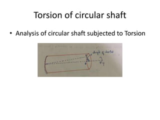
Analysis of circular shaft subjected to Torsion
•Download as PPTX, PDF•
0 likes•18 views
analysis of shaft in torsion
Report
Share
Report
Share

Recommended
chapter3_Shaft.ppt
This document discusses the design and properties of shafts, keys, couplings, and gears used in mechanical engineering. It covers the following key points:
- Shafts are rotating elements that transmit power and torque from one place to another. They experience both twisting moments and bending stresses.
- Common materials for shafts include various grades of carbon steel. Shaft size is determined based on required strength, rigidity, and stresses from torque and bending loads.
- Keys are inserted between shafts and machine elements like pulleys to prevent relative motion and transmit torque. Couplings are used to connect two shafts together.
- Gears transmit power between shafts and change speed or torque. The document
Unit 2 Shafts and Coupling.pptx
1. The document describes a horizontal shaft supported by bearings at each end that carries two gears.
2. Gears C and D are located 250mm and 400mm from their respective bearings and have pitch diameters of 600mm and 200mm.
3. The shaft transmits 20kW of power at 120rpm, delivered at gear C and taken out at gear D, with vertical tooth pressures on each gear.
4. The question asks to determine the shaft diameter if the working stresses are 100MPa in tension and 56MPa in shear.
Torsion_2.pdf
The document discusses torsion and torsional deformation of circular shafts. It defines torsion as a moment that twists a member about its longitudinal axis. For a circular shaft under pure torsion, the angle of twist is linearly proportional to the distance along the shaft. The maximum shear stress occurs at the outer surface of the shaft and is calculated using the torsion formula. Non-uniform torsion is analyzed by dividing the shaft into segments or using differential elements and integrating along the length. The document also provides examples of solving for shear stress and required shaft diameter given applied torques.
Design of machine elements -unit2.pptx
A shaft is a rotating machine element which is used to transmit power from one place to another. with help of couplings or gears.
The shafts are usually cylindrical, but may be square or cross-shaped in section. They are solid in cross-section but
sometimes hollow shafts are also used.
Types of Shafts
The following two types of shafts are important from the subject point of view :
Transmission shafts. These shafts transmit power between the source and the machines absorbing power. The counter shafts, line shafts, over head shafts and all factory shafts are transmission shafts. Since these shafts carry machine parts such as pulleys, gears etc., therefore they are subjected to bending in addition to twisting.
2. Machine shafts. These shafts form an integral part of the machine itself. The crank shaft is an example of machine shaft.
Stresses in Shafts
The following stresses are induced in the shafts :
1. Shear stresses due to the transmission of torque (i.e. due to torsional load).
2. Bending stresses (tensile or compressive) due to the forces acting upon machine elements like gears, pulleys etc. as well as due to the weight of the shaft itself.
3. Stresses due to combined torsional and bending loads.
Material Used for Shafts
The material used for shafts should have the following properties :
1. It should have high strength.
2. It should have good machinability.
3. It should have low notch sensitivity factor.
4. It should have good heat treatment properties.
5. It should have high wear resistant properties.
The material used for ordinary shafts is carbon steel of grades 40 C 8, 45 C 8, 50 C 4 and 50 C 12.
The mechanical properties of these grades of carbon steel are given in the following table.
torsion
The document provides an overview of mechanics of materials concepts related to torsion, including:
- Torsion causes shearing stresses that vary linearly from zero at the center to a maximum at the surface for circular shafts.
- Torsion can cause both shearing stresses and normal stresses depending on the orientation of the material element.
- Ductile materials fail in shear while brittle materials fail in tension when subjected to torsion.
- The angle of twist is proportional to the applied torque, material properties, and shaft length based on elastic torsion formulas.
- Stress concentrations can occur due to geometric discontinuities and influence the maximum shearing stress.
polyphase induction motor
The document summarizes the key aspects of polyphase induction motors, including:
1) Nikola Tesla conceived the induction motor in 1883 and sold the rights to George Westinghouse. Most large industrial motors are polyphase induction motors with multiple stator windings driven by time-shifted sine waves, usually two or three phases.
2) An induction motor has a rotor and stator, with the stator windings connected to a polyphase power source. The rotating magnetic field produced by the stator induces current in the rotor, causing it to turn.
3) The induction motor is simple and reliable compared to DC motors as the rotor has no commutator or brushes. Torque is
Chapter 4: Torsion
This document summarizes concepts related to torsion and the torsion of circular elastic bars. It discusses the assumptions made in analyzing torsion, including that shear strain varies linearly from the central axis. It also covers determining shear stress and torque using the polar moment of inertia for circular cross-sections. The relationships between applied torque, shear stress, shear strain, and angle of twist are defined. Stress concentrations and alternative differential equations approaches are also summarized.
Orthodontic arch wirs ii
This document provides a summary of orthodontic arch wires for clinical use. It discusses the properties and requirements of different wire types for various stages of treatment including alignment, leveling, retraction, and finishing. For alignment, lighter force wires like nickel titanium are preferred. Leveling can be achieved using wires with built-in curves. Retraction can occur via sliding mechanics using stainless steel wires or loop mechanics. Finishing requires precise torque control, which rectangular wires can provide if the fit between wire and bracket is tight. A variety of wire shapes, sizes, and materials are available to clinicians to facilitate efficient tooth movement.
5 shaft shafts subjected to combined twisting moment and bending moment
1. The document discusses the design of shafts that are subjected to both twisting moments and bending moments.
2. It describes two theories for analyzing combined stresses: maximum shear stress theory for ductile materials like steel, and maximum normal stress theory for brittle materials like cast iron.
3. It provides an example of determining the diameter of a shaft made of 45 C 8 steel that is subjected to a bending moment of 3000 N-m and torque of 10,000 N-m, with a safety factor of 6.
A
1. The document describes a weapon subsystem for a robot that has a maximum height of 45mm and length of 140mm. It includes calculations for inertia, angular velocity, and torque of the subsystem.
2. The subsystem parts include two V-belt pulleys, one V-belt, two bearings, one steel shaft, and one steel bar made of welded steel plates.
3. The objective is to be effective against opposition robots while meeting team and university requirements of durability, weight, length, torque, etc. It describes how each requirement is satisfied by the subsystem design.
Synchronous Generators.pptx
This document provides an overview of synchronous generators/alternators. It discusses the different types of rotor constructions including salient pole and cylindrical rotor types. It covers the basic working principle of an alternator including EMF generation and factors that affect output voltage such as armature reaction under different load power factors. Key concepts like winding configurations, pitch factor, distribution factor and EMF equation are explained. Causes of voltage regulation under load conditions due to armature resistance, reactance and armature reaction are summarized.
Junaid meenakshi dental college
This document discusses multi-stranded orthodontic archwires. It explains that they are composed of multiple thin wire strands twisted or braided together to form a wire with a small diameter but high flexibility and strength. The document covers the types of multi-stranded wires available, their mechanical properties, advantages over solid wires for initial alignment, and clinical uses. It provides details on superelastic nickel-titanium coaxial wires like Supercable that deliver very light continuous forces ideal for initial leveling.
Unit 2 Design Of Shafts Keys and Couplings
This document provides information about the design of shafts, keys, and couplings. It discusses transmission shafts, stresses induced in shafts, and shaft design based on strength and rigidity. It presents formulas for shaft design using maximum shear stress theory, distortion energy theory, and the ASME code. Several examples are provided to demonstrate how to calculate the diameter of a shaft given the power transmitted, loads on the shaft, material properties, and other parameters using these theories and codes. Assignments involving similar calculations of shaft diameters are presented.
SHAFTS And Its Mechanical Properties.pptx
A shaft transmits power from one place to another through rotation. It experiences shear stresses from torque transmission and bending stresses from attached machine elements like gears and pulleys. Common materials are steel alloys selected for strength, machinability, and resistance to wear and corrosion. Shafts are classified by their application like transmission, machine, or axle shafts. Solid shafts experience higher stresses but can transmit torque more efficiently, while hollow shafts are lighter with potential vibration issues. Shaft design considers both torsional and bending stresses to ensure safety factors below material yield points and within deflection/twist limits.
Problems on Torsion
The document contains 8 questions related to determining the diameter of solid and hollow shafts based on transmitted power, torque, maximum shear stress, and angle of twist specifications. The questions involve calculating shaft diameters, transmitted torque values, shear stresses, and comparing weights of solid versus hollow shaft designs.
DC Generator
This document discusses the key components and operating principles of DC generators. It describes the essential parts of a practical generator including the magnetic frame, pole cores, field coils, armature core, armature windings, commutator, brushes and bearings. It also covers different types of armature windings such as lap and wave windings. Finally, it discusses losses that occur in DC generators and conditions for maximum efficiency.
Dc Motor Construction and Working
1. DC motors have a stationary stator that contains electromagnets and a rotating armature.
2. When DC current passes through the electromagnets, it creates a magnetic field that interacts with the magnetic field of the armature coils, producing rotational force.
3. The commutator and brushes ensure that the direction of current in each armature coil remains constant, causing continuous rotation of the armature as each coil's magnetic field switches poles.
Unit 4 Design of Power Screw and Screw Jack
The document discusses power screws, including their terminology, types of threads, torque analysis, and efficiency. It defines key terms like nominal diameter, pitch, lead, and lead angle. It describes common types of threads like square, ACME, and buttress threads. It discusses torque required to raise and lower loads, including expressions for self-locking and overhauling screws. The document also covers screw efficiency and collar friction torque, providing expressions to calculate overall efficiency. An example calculation is given to find maximum load lifted, efficiency, and overall efficiency of a screw jack.
Simple torsion equation
The document discusses torsion in shafts. When equal and opposite torques are applied to the ends of a shaft, it experiences twisting and shear stresses. For a circular shaft under torsion, every cross-section remains undistorted due to symmetry. Shear stress is highest at the outer surface and lowest at the axis. The maximum torque a circular solid shaft can transmit depends on the shear stress limit and material properties. Polar modulus is a measure of a shaft's resistance to twisting. Torsional rigidity describes a shaft's resistance to twisting deformation.
Fasteners.pdf
Threaded fasteners such as bolts and screws join components together through the transformation of rotational motion into linear motion. There are various thread standards that specify attributes like diameter, pitch, class of fit, and thread type. Early threaded fasteners lacked standardization but efforts in the 18th-19th centuries established conventions for sizes. Modern standards include metric and unified external and internal thread systems.
Space closure
This document discusses two main types of space closure mechanics in orthodontic treatment: closing loop archwires and sliding mechanics. Closing loop archwires involve individually fabricated loops to retract teeth into extraction spaces, while sliding mechanics use elastic chains or coil springs to slide teeth along archwires into spaces. The document provides details on techniques, advantages, and disadvantages of each approach as well as factors influencing effective space closure.
armature Winding
Winding
What is Armature winding?
Terms related to armature winding.
Single layer and double layer windings.
Comparison between closed and open windings.
Types of DC armature winding.
Types of AC armature winding.
Shaft
The document discusses various types of shafts and shaft couplings. It provides information on shaft materials, sizing, layout and design considerations. Regarding couplings, it describes rigid couplings like sleeve, flange and marine couplings. It also discusses flexible bush pin couplings. Key points covered include shaft material selection, stress analysis for sizing, deflection requirements, coupling design for strength, rigidity and alignment between connected shafts. Common shaft and coupling types, their designs and applications are explained.
Mechanical principles in orthodontic force control
The document discusses the mechanical principles behind orthodontic force control using elastic materials. It describes the basic properties of elastic materials, including stress, strain, stiffness, and strength. Different orthodontic archwire materials are examined, including precious metals, stainless steel, cobalt-chromium alloys, and nickel-titanium alloys. Nickel-titanium alloys are highlighted for their ability to apply light forces over a large range through properties like shape memory and superelasticity, due to a reversible crystal structure transition between martensite and austenite phases.
Transformer Designing
The document provides information on transformer design specifications and considerations. It discusses technical specifications for a 500KVA, 3 phase transformer including input/output voltages and power ratings. It also covers initial calculations, losses in transformers, core materials and construction, winding design, insulation, cooling methods, and connection configurations. The goal is to design a transformer that efficiently transfers power while meeting specifications for voltage, current, temperature rise and other factors.
Maeen lecture corrected
The document discusses methods for closing spaces during orthodontic treatment. It describes two main methods: sliding mechanics and loop mechanics. Sliding mechanics involve sliding brackets along the archwire using elastics or coils, while loop mechanics use loops of wire between brackets to close spaces without bracket movement. The document outlines considerations for each method and discusses techniques for closing extraction spaces and retracting canines specifically. It also notes potential problems and solutions during space closure.
More Related Content
Similar to Analysis of circular shaft subjected to Torsion
Orthodontic arch wirs ii
This document provides a summary of orthodontic arch wires for clinical use. It discusses the properties and requirements of different wire types for various stages of treatment including alignment, leveling, retraction, and finishing. For alignment, lighter force wires like nickel titanium are preferred. Leveling can be achieved using wires with built-in curves. Retraction can occur via sliding mechanics using stainless steel wires or loop mechanics. Finishing requires precise torque control, which rectangular wires can provide if the fit between wire and bracket is tight. A variety of wire shapes, sizes, and materials are available to clinicians to facilitate efficient tooth movement.
5 shaft shafts subjected to combined twisting moment and bending moment
1. The document discusses the design of shafts that are subjected to both twisting moments and bending moments.
2. It describes two theories for analyzing combined stresses: maximum shear stress theory for ductile materials like steel, and maximum normal stress theory for brittle materials like cast iron.
3. It provides an example of determining the diameter of a shaft made of 45 C 8 steel that is subjected to a bending moment of 3000 N-m and torque of 10,000 N-m, with a safety factor of 6.
A
1. The document describes a weapon subsystem for a robot that has a maximum height of 45mm and length of 140mm. It includes calculations for inertia, angular velocity, and torque of the subsystem.
2. The subsystem parts include two V-belt pulleys, one V-belt, two bearings, one steel shaft, and one steel bar made of welded steel plates.
3. The objective is to be effective against opposition robots while meeting team and university requirements of durability, weight, length, torque, etc. It describes how each requirement is satisfied by the subsystem design.
Synchronous Generators.pptx
This document provides an overview of synchronous generators/alternators. It discusses the different types of rotor constructions including salient pole and cylindrical rotor types. It covers the basic working principle of an alternator including EMF generation and factors that affect output voltage such as armature reaction under different load power factors. Key concepts like winding configurations, pitch factor, distribution factor and EMF equation are explained. Causes of voltage regulation under load conditions due to armature resistance, reactance and armature reaction are summarized.
Junaid meenakshi dental college
This document discusses multi-stranded orthodontic archwires. It explains that they are composed of multiple thin wire strands twisted or braided together to form a wire with a small diameter but high flexibility and strength. The document covers the types of multi-stranded wires available, their mechanical properties, advantages over solid wires for initial alignment, and clinical uses. It provides details on superelastic nickel-titanium coaxial wires like Supercable that deliver very light continuous forces ideal for initial leveling.
Unit 2 Design Of Shafts Keys and Couplings
This document provides information about the design of shafts, keys, and couplings. It discusses transmission shafts, stresses induced in shafts, and shaft design based on strength and rigidity. It presents formulas for shaft design using maximum shear stress theory, distortion energy theory, and the ASME code. Several examples are provided to demonstrate how to calculate the diameter of a shaft given the power transmitted, loads on the shaft, material properties, and other parameters using these theories and codes. Assignments involving similar calculations of shaft diameters are presented.
SHAFTS And Its Mechanical Properties.pptx
A shaft transmits power from one place to another through rotation. It experiences shear stresses from torque transmission and bending stresses from attached machine elements like gears and pulleys. Common materials are steel alloys selected for strength, machinability, and resistance to wear and corrosion. Shafts are classified by their application like transmission, machine, or axle shafts. Solid shafts experience higher stresses but can transmit torque more efficiently, while hollow shafts are lighter with potential vibration issues. Shaft design considers both torsional and bending stresses to ensure safety factors below material yield points and within deflection/twist limits.
Problems on Torsion
The document contains 8 questions related to determining the diameter of solid and hollow shafts based on transmitted power, torque, maximum shear stress, and angle of twist specifications. The questions involve calculating shaft diameters, transmitted torque values, shear stresses, and comparing weights of solid versus hollow shaft designs.
DC Generator
This document discusses the key components and operating principles of DC generators. It describes the essential parts of a practical generator including the magnetic frame, pole cores, field coils, armature core, armature windings, commutator, brushes and bearings. It also covers different types of armature windings such as lap and wave windings. Finally, it discusses losses that occur in DC generators and conditions for maximum efficiency.
Dc Motor Construction and Working
1. DC motors have a stationary stator that contains electromagnets and a rotating armature.
2. When DC current passes through the electromagnets, it creates a magnetic field that interacts with the magnetic field of the armature coils, producing rotational force.
3. The commutator and brushes ensure that the direction of current in each armature coil remains constant, causing continuous rotation of the armature as each coil's magnetic field switches poles.
Unit 4 Design of Power Screw and Screw Jack
The document discusses power screws, including their terminology, types of threads, torque analysis, and efficiency. It defines key terms like nominal diameter, pitch, lead, and lead angle. It describes common types of threads like square, ACME, and buttress threads. It discusses torque required to raise and lower loads, including expressions for self-locking and overhauling screws. The document also covers screw efficiency and collar friction torque, providing expressions to calculate overall efficiency. An example calculation is given to find maximum load lifted, efficiency, and overall efficiency of a screw jack.
Simple torsion equation
The document discusses torsion in shafts. When equal and opposite torques are applied to the ends of a shaft, it experiences twisting and shear stresses. For a circular shaft under torsion, every cross-section remains undistorted due to symmetry. Shear stress is highest at the outer surface and lowest at the axis. The maximum torque a circular solid shaft can transmit depends on the shear stress limit and material properties. Polar modulus is a measure of a shaft's resistance to twisting. Torsional rigidity describes a shaft's resistance to twisting deformation.
Fasteners.pdf
Threaded fasteners such as bolts and screws join components together through the transformation of rotational motion into linear motion. There are various thread standards that specify attributes like diameter, pitch, class of fit, and thread type. Early threaded fasteners lacked standardization but efforts in the 18th-19th centuries established conventions for sizes. Modern standards include metric and unified external and internal thread systems.
Space closure
This document discusses two main types of space closure mechanics in orthodontic treatment: closing loop archwires and sliding mechanics. Closing loop archwires involve individually fabricated loops to retract teeth into extraction spaces, while sliding mechanics use elastic chains or coil springs to slide teeth along archwires into spaces. The document provides details on techniques, advantages, and disadvantages of each approach as well as factors influencing effective space closure.
armature Winding
Winding
What is Armature winding?
Terms related to armature winding.
Single layer and double layer windings.
Comparison between closed and open windings.
Types of DC armature winding.
Types of AC armature winding.
Shaft
The document discusses various types of shafts and shaft couplings. It provides information on shaft materials, sizing, layout and design considerations. Regarding couplings, it describes rigid couplings like sleeve, flange and marine couplings. It also discusses flexible bush pin couplings. Key points covered include shaft material selection, stress analysis for sizing, deflection requirements, coupling design for strength, rigidity and alignment between connected shafts. Common shaft and coupling types, their designs and applications are explained.
Mechanical principles in orthodontic force control
The document discusses the mechanical principles behind orthodontic force control using elastic materials. It describes the basic properties of elastic materials, including stress, strain, stiffness, and strength. Different orthodontic archwire materials are examined, including precious metals, stainless steel, cobalt-chromium alloys, and nickel-titanium alloys. Nickel-titanium alloys are highlighted for their ability to apply light forces over a large range through properties like shape memory and superelasticity, due to a reversible crystal structure transition between martensite and austenite phases.
Transformer Designing
The document provides information on transformer design specifications and considerations. It discusses technical specifications for a 500KVA, 3 phase transformer including input/output voltages and power ratings. It also covers initial calculations, losses in transformers, core materials and construction, winding design, insulation, cooling methods, and connection configurations. The goal is to design a transformer that efficiently transfers power while meeting specifications for voltage, current, temperature rise and other factors.
Maeen lecture corrected
The document discusses methods for closing spaces during orthodontic treatment. It describes two main methods: sliding mechanics and loop mechanics. Sliding mechanics involve sliding brackets along the archwire using elastics or coils, while loop mechanics use loops of wire between brackets to close spaces without bracket movement. The document outlines considerations for each method and discusses techniques for closing extraction spaces and retracting canines specifically. It also notes potential problems and solutions during space closure.
Similar to Analysis of circular shaft subjected to Torsion (20)
5 shaft shafts subjected to combined twisting moment and bending moment
5 shaft shafts subjected to combined twisting moment and bending moment
Mechanical principles in orthodontic force control
Mechanical principles in orthodontic force control
More from SatishKotwal
Limit state of collapse shear (1).pptx
The document discusses the design of shear reinforcement in beams. It defines types of shear reinforcement like vertical stirrups, bent up bars, and inclined stirrups. It explains that the critical section for shear is at a distance d from the support face, where d is the effective depth. It provides design steps for calculating shear force, nominal shear stress, maximum shear stress in concrete, design shear strength in concrete, and determining if minimum or design shear reinforcement is required. Several examples are given applying these steps to design shear reinforcement for beams.
limit state of collapse flexure.pptx
This document discusses the behavior and analysis of doubly reinforced concrete beam sections. It provides information on:
- The behavior of a doubly reinforced section with two stress blocks - one for the tension steel and one for the compression steel.
- The equations used to calculate the depth of the neutral axis and ultimate moment resistance for a doubly reinforced section.
- How the stress in compression steel (σsc) is determined, either from tables or through trial and error based on the steel grade.
- Examples of analysis problems solving for the depth of neutral axis, σsc, and ultimate moment resistance of given doubly reinforced beam sections.
- The design process for a doubly reinforced section, including determining the amounts of tension and compression steel
introduction to rcc.pptx
This document discusses different design methods and concepts in structural engineering including:
- Stress-strain curves and their elastic and plastic regions for materials like concrete and steel.
- Load factors which are used to enhance working loads based on material strength characteristics.
- Failure criteria based on stress, strain, and load at failure.
- Limit state design which considers the limit states of serviceability, durability, and collapse based on characteristic material strengths, loads, and partial safety factors.
DCS II.pptx
DCS II is a new system that has been developed to replace the previous DCS system. It features improved processing capabilities and security features compared to the prior version. The new DCS II aims to streamline operations and provide enhanced functionality for users.
APPLIED MECHANICS online lecture.pptx
The document discusses key concepts in applied mechanics. It begins by defining Newton's three laws of motion - the first law of inertia, the second law relating force and acceleration, and the third law of action-reaction forces. It then defines Newton's law of universal gravitation. The rest of the document outlines the syllabus for a course in applied mechanics, listing topics like statics, kinetics, centroids, and moments of inertia. It provides several reference books for further study.
APPLIED MECHANICS (1).ppt
The document discusses key concepts in applied mechanics. It begins by defining Newton's three laws of motion - the first law of inertia, the second law relating force and acceleration, and the third law of action-reaction forces. It then defines Newton's law of universal gravitation. The rest of the document outlines the syllabus for a course in applied mechanics, listing topics like statics, kinetics, centroids, and moments of inertia. It provides several reference books for further study.
trapezoidal rule.pptx
This document discusses various numerical integration techniques including the Trapezoidal rule, Simpson's 1/3 rule, and Simpson's 3/8 rule. These rules allow approximating the definite integral of a function from a set of tabulated values of the integrand. Examples are provided to demonstrate applying each rule to calculate the area under curves and integrals of specific functions over given intervals in 1-3 sentences.
DCS II.pptx
DCS II is a new system that has been developed to replace the previous DCS system. It features improved processing capabilities and security features compared to the prior version. The new DCS II aims to streamline operations and provide enhanced functionality for users.
More from SatishKotwal (10)
Recently uploaded
bank management system in java and mysql report1.pdf
truth is high but higher still is truth full living
Recycled Concrete Aggregate in Construction Part III
Using recycled concrete aggregates (RCA) for pavements is crucial to achieving sustainability. Implementing RCA for new pavement can minimize carbon footprint, conserve natural resources, reduce harmful emissions, and lower life cycle costs. Compared to natural aggregate (NA), RCA pavement has fewer comprehensive studies and sustainability assessments.
A SYSTEMATIC RISK ASSESSMENT APPROACH FOR SECURING THE SMART IRRIGATION SYSTEMS
The smart irrigation system represents an innovative approach to optimize water usage in agricultural and landscaping practices. The integration of cutting-edge technologies, including sensors, actuators, and data analysis, empowers this system to provide accurate monitoring and control of irrigation processes by leveraging real-time environmental conditions. The main objective of a smart irrigation system is to optimize water efficiency, minimize expenses, and foster the adoption of sustainable water management methods. This paper conducts a systematic risk assessment by exploring the key components/assets and their functionalities in the smart irrigation system. The crucial role of sensors in gathering data on soil moisture, weather patterns, and plant well-being is emphasized in this system. These sensors enable intelligent decision-making in irrigation scheduling and water distribution, leading to enhanced water efficiency and sustainable water management practices. Actuators enable automated control of irrigation devices, ensuring precise and targeted water delivery to plants. Additionally, the paper addresses the potential threat and vulnerabilities associated with smart irrigation systems. It discusses limitations of the system, such as power constraints and computational capabilities, and calculates the potential security risks. The paper suggests possible risk treatment methods for effective secure system operation. In conclusion, the paper emphasizes the significant benefits of implementing smart irrigation systems, including improved water conservation, increased crop yield, and reduced environmental impact. Additionally, based on the security analysis conducted, the paper recommends the implementation of countermeasures and security approaches to address vulnerabilities and ensure the integrity and reliability of the system. By incorporating these measures, smart irrigation technology can revolutionize water management practices in agriculture, promoting sustainability, resource efficiency, and safeguarding against potential security threats.
Embedded machine learning-based road conditions and driving behavior monitoring
Car accident rates have increased in recent years, resulting in losses in human lives, properties, and other financial costs. An embedded machine learning-based system is developed to address this critical issue. The system can monitor road conditions, detect driving patterns, and identify aggressive driving behaviors. The system is based on neural networks trained on a comprehensive dataset of driving events, driving styles, and road conditions. The system effectively detects potential risks and helps mitigate the frequency and impact of accidents. The primary goal is to ensure the safety of drivers and vehicles. Collecting data involved gathering information on three key road events: normal street and normal drive, speed bumps, circular yellow speed bumps, and three aggressive driving actions: sudden start, sudden stop, and sudden entry. The gathered data is processed and analyzed using a machine learning system designed for limited power and memory devices. The developed system resulted in 91.9% accuracy, 93.6% precision, and 92% recall. The achieved inference time on an Arduino Nano 33 BLE Sense with a 32-bit CPU running at 64 MHz is 34 ms and requires 2.6 kB peak RAM and 139.9 kB program flash memory, making it suitable for resource-constrained embedded systems.
Technical Drawings introduction to drawing of prisms
Method of technical Drawing of prisms,and cylinders.
5214-1693458878915-Unit 6 2023 to 2024 academic year assignment (AutoRecovere...
Bigdata of technology
IEEE Aerospace and Electronic Systems Society as a Graduate Student Member
IEEE Aerospace and Electronic Systems Society as a Graduate Student Member
[JPP-1] - (JEE 3.0) - Kinematics 1D - 14th May..pdf
Kinematics 11th jpp- 01. ( Solved ) unacademy namo kaul on 14th may...
Advanced control scheme of doubly fed induction generator for wind turbine us...
This paper describes a speed control device for generating electrical energy on an electricity network based on the doubly fed induction generator (DFIG) used for wind power conversion systems. At first, a double-fed induction generator model was constructed. A control law is formulated to govern the flow of energy between the stator of a DFIG and the energy network using three types of controllers: proportional integral (PI), sliding mode controller (SMC) and second order sliding mode controller (SOSMC). Their different results in terms of power reference tracking, reaction to unexpected speed fluctuations, sensitivity to perturbations, and resilience against machine parameter alterations are compared. MATLAB/Simulink was used to conduct the simulations for the preceding study. Multiple simulations have shown very satisfying results, and the investigations demonstrate the efficacy and power-enhancing capabilities of the suggested control system.
International Conference on NLP, Artificial Intelligence, Machine Learning an...
International Conference on NLP, Artificial Intelligence, Machine Learning and Applications (NLAIM 2024) offers a premier global platform for exchanging insights and findings in the theory, methodology, and applications of NLP, Artificial Intelligence, Machine Learning, and their applications. The conference seeks substantial contributions across all key domains of NLP, Artificial Intelligence, Machine Learning, and their practical applications, aiming to foster both theoretical advancements and real-world implementations. With a focus on facilitating collaboration between researchers and practitioners from academia and industry, the conference serves as a nexus for sharing the latest developments in the field.
22CYT12-Unit-V-E Waste and its Management.ppt
Introduction- e - waste – definition - sources of e-waste– hazardous substances in e-waste - effects of e-waste on environment and human health- need for e-waste management– e-waste handling rules - waste minimization techniques for managing e-waste – recycling of e-waste - disposal treatment methods of e- waste – mechanism of extraction of precious metal from leaching solution-global Scenario of E-waste – E-waste in India- case studies.
哪里办理(csu毕业证书)查尔斯特大学毕业证硕士学历原版一模一样
原版一模一样【微信:741003700 】【(csu毕业证书)查尔斯特大学毕业证硕士学历】【微信:741003700 】学位证,留信认证(真实可查,永久存档)offer、雅思、外壳等材料/诚信可靠,可直接看成品样本,帮您解决无法毕业带来的各种难题!外壳,原版制作,诚信可靠,可直接看成品样本。行业标杆!精益求精,诚心合作,真诚制作!多年品质 ,按需精细制作,24小时接单,全套进口原装设备。十五年致力于帮助留学生解决难题,包您满意。
本公司拥有海外各大学样板无数,能完美还原海外各大学 Bachelor Diploma degree, Master Degree Diploma
1:1完美还原海外各大学毕业材料上的工艺:水印,阴影底纹,钢印LOGO烫金烫银,LOGO烫金烫银复合重叠。文字图案浮雕、激光镭射、紫外荧光、温感、复印防伪等防伪工艺。材料咨询办理、认证咨询办理请加学历顾问Q/微741003700
留信网认证的作用:
1:该专业认证可证明留学生真实身份
2:同时对留学生所学专业登记给予评定
3:国家专业人才认证中心颁发入库证书
4:这个认证书并且可以归档倒地方
5:凡事获得留信网入网的信息将会逐步更新到个人身份内,将在公安局网内查询个人身份证信息后,同步读取人才网入库信息
6:个人职称评审加20分
7:个人信誉贷款加10分
8:在国家人才网主办的国家网络招聘大会中纳入资料,供国家高端企业选择人才
Iron and Steel Technology Roadmap - Towards more sustainable steelmaking.pdf
Iron and Steel Technology towards Sustainable Steelmaking
Recently uploaded (20)
bank management system in java and mysql report1.pdf
bank management system in java and mysql report1.pdf
Recycled Concrete Aggregate in Construction Part III
Recycled Concrete Aggregate in Construction Part III
A SYSTEMATIC RISK ASSESSMENT APPROACH FOR SECURING THE SMART IRRIGATION SYSTEMS
A SYSTEMATIC RISK ASSESSMENT APPROACH FOR SECURING THE SMART IRRIGATION SYSTEMS
Embedded machine learning-based road conditions and driving behavior monitoring
Embedded machine learning-based road conditions and driving behavior monitoring
Technical Drawings introduction to drawing of prisms
Technical Drawings introduction to drawing of prisms
5214-1693458878915-Unit 6 2023 to 2024 academic year assignment (AutoRecovere...
5214-1693458878915-Unit 6 2023 to 2024 academic year assignment (AutoRecovere...
Manufacturing Process of molasses based distillery ppt.pptx
Manufacturing Process of molasses based distillery ppt.pptx
IEEE Aerospace and Electronic Systems Society as a Graduate Student Member
IEEE Aerospace and Electronic Systems Society as a Graduate Student Member
[JPP-1] - (JEE 3.0) - Kinematics 1D - 14th May..pdf
[JPP-1] - (JEE 3.0) - Kinematics 1D - 14th May..pdf
Advanced control scheme of doubly fed induction generator for wind turbine us...
Advanced control scheme of doubly fed induction generator for wind turbine us...
International Conference on NLP, Artificial Intelligence, Machine Learning an...
International Conference on NLP, Artificial Intelligence, Machine Learning an...
ML Based Model for NIDS MSc Updated Presentation.v2.pptx
ML Based Model for NIDS MSc Updated Presentation.v2.pptx
basic-wireline-operations-course-mahmoud-f-radwan.pdf
basic-wireline-operations-course-mahmoud-f-radwan.pdf
Iron and Steel Technology Roadmap - Towards more sustainable steelmaking.pdf
Iron and Steel Technology Roadmap - Towards more sustainable steelmaking.pdf
Analysis of circular shaft subjected to Torsion
- 1. Torsion of circular shaft • Analysis of circular shaft subjected to Torsion
- 2. Analysis of circular shaft subjected to Torsion • The shaft is considered to be in pure torsion if it is subject to two opposing turning moments. This causes the shaft to shear off at every perpendicular cross-section. This moment or torsion will bend the circular shafts without affecting the shaft's cross- section.
- 3. Assumption in the theory of pure torsion • The material is homogeneous and isotropic • Hook's law is obeyed by the material. • The shaft is circular in section. • The cross-section of the shaft remains uniform throughout. • The shaft is subjected to pure torque only. • The shaft is not subjected to any initial torque. • The transverse sections which were plane before application of torque remain plane even after application of torque.
- 4. Maximum Torsion transmitted by solid circular shaft
- 5. Maximum Torsion transmitted by hollow circular shaft
- 6. Power transmitted by shaft
- 7. Problem • Find the power transmitted by a shaft 50mm in diameter at 2.5rev/sec if the max permissible shear stress is 80N/mm2?
- 11. Problem • A solid shaft 80mm in diameter transmit 80KN ot 180rev/min. Calculate the max shear induced & the angle of twist in degree for a length of 8m consider G = 80000N/mm2
- 15. Problem • A solid shaft has to transmit 60KW at 10/3 hz. The max torque transmitted in each revolution exceeds the mean by 30%. If the shear stress is not to exceed 80N/mm2. find a suitable diameter for the shaft?
- 19. Shaft in series • When two shaft are connected so as to remain continuous lengthwise they are said to be in series
- 21. Shaft in parallel • When two shaft are connected so as to remain surrounded in two shaft are said to be in parallel
- 23. Problem • A solid steel shaft 50mm in diameter is fixed rigidly & concentrically inside a bronze sleeve 75mm external diameter. Find the angle of twist in a 1.5m length of the composite shaft under the action of a torque of 8Nm modulus of rigidity of steel is 8x10 4 N/mm2 & that of bronze is 4x10 4 N/mm2?