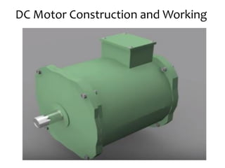
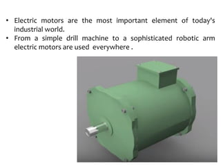
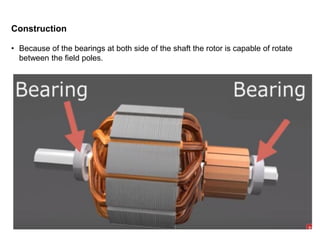
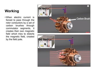
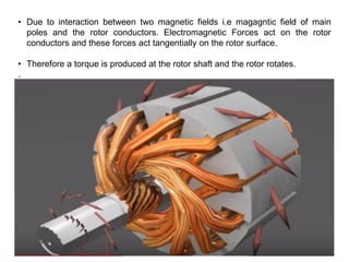
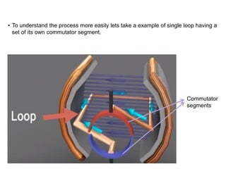
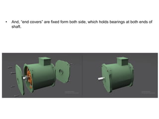
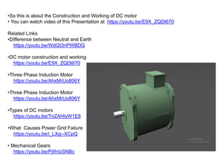
Mechanic Electric Vehicle
(Motors)
Omkar Kore
DC Motor Construction and Working
• Electric motors are the most important element of today's
industrial world.
• From a simple drill machine to a sophisticated robotic arm
electric motors are used everywhere .
Types
There are two types of electric motors-
1. AC Motors
2. DC Motors
• In these, because of some important characteristics like fast reaction, better speed
control, simple construction, DC motors are very popular in automatic machines.
AC motor
DC motor
Construction
• The outer part of the motor is
generally static, which is
known as stator.
• Stator consist of a frame, and
it contains “Pole Shoes”
which are projected inward.
Construction
• Core of these poles are made from silicon
steel on which insulated copper wire is
wound to make windings.
• These poles are bolted and fixed inside the
frame.
Core
Construction
• When DC current is pass through the windings it creates a static magnetic field.
• There are two types of pole in a DC machine.
1. Main/ Field Pole
2. Inter Poles
Construction
• The connections of these poles are brought out through connectors in
the terminal box, so that we can give electric supply to them and even
do the check for the fault.
• Main poles create static magnetic field, when current is pass to its
winding.
Construction
• In this magnetic field rotating part of motor lies, known as Rotor or Armature which
is made by number of stampings of highly permeable material i.e. silicon steel,
which allows magnetic field to pass through it easily.
Construction
• Slots are cut on the outer periphery of rotor or we can say “armature”, which
receive coils/windings made up of copper conductor.
• Each coil gets connected to an external DC source by a pair of commutator
segments arranged in the form of a Ring.
Construction
•This complete assembly is housed over a cylindrical shaft made up of high quality
steel.
Construction
• Because of the bearings at both side of the shaft the rotor is capable of rotate
between the field poles.
Working
• When electric current is
forced to pass through the
rotor conductors by a set of
carbon brushes through
commutator segments, it
creates their own magnetic
field which tries to distorts
the magnetic field, created
by the field pole.
• Due to interaction between two magnetic fields i.e magagntic field of main
poles and the rotor conductors. Electromagnetic Forces act on the rotor
conductors and these forces act tangentially on the rotor surface.
• Therefore a torque is produced at the rotor shaft and the rotor rotates.
.
• To understand the process more easily lets take a example of single loop having a
set of its own commutator segment.
Commutator
segments
• Due to the DC voltage applied by an external DC source current will flow in the
coil in given direction from positive to negative potential and by Fleming's left
hand rule , we can find that this side of coil receive force in upward direction
and this side will receive a downward force and hence the loop rotates.
Current
• During the rotation of loop you can find that commutator segments comes in
contact with brushes of opposite polarity one by one.
• This way the conductor of left side always carry current in given direction, and
of right side in opposite direction.
• This helps to maintain the continuous rotation of coil.
• We can also find that magnitude of force on the coil is maximum in this region
after that, magnitude reduce reduces considerably.
• This cause uneven torque and moment of rotor.
• To make “maximum torque” always available at the shaft of rotor multiple
number of coils with a pair of commutator segments are placed in the rotor.
•When one coil passes through the region of maximum torque next coil will take its place.
•This way shaft of rotor always provide higher and smooth torque.
•Coils are connected to commutator segment in such a way that every instant of time each and every coil
carries current, but the sides of coil to comes at the left hand side carries current in one direction and the
side at right hand carries current in opposite direction respective of the rotor position.
•This can be achieved by the lap or wave connection windings.
• To ensure that the current given to the commutator segments will not reach to the shaft Mica Insulation
is placed between them.
• In small DC motor permanent magnet can be use to create static magnetic field,
but they can loose their magnetism due to heating, vibration, or aging, that’s why
in higher rating motor electromagnets are used and their magnetic
field density can be controlled to control output torque.
Lets have a look at the coil design, if a single turn coil of thick wire is used here
then it allow higher current and give higher torque. Whereas, if multi-turn coil of
thin wire is used then current and torque is also reduced but we get higher speed
Single turn coil Multi- turn coil
• That means at the time of manufacturing we can decide whether we want high
torque low speed machine or low toque high speed machine.
• Here the work of interpole is to reduce sparking at the brushes over commutator
ring due to the effect of armature reaction.
• To energized the field poles we can use same DC source which runs our DC
motor or we can use a separated source , the method which is used will decide
the type of DC motor.
High torque low speed machine Low toque high speed machine
• At last all terminals are brought out through terminal box.
• And, “end covers” are fixed form both side, which holds bearings at both ends of
shaft.
•So this is about the Construction and Working of DC motor
• You can watch video of this Presentation at https://youtu.be/E9X_ZQDt670
Related Links
•Difference between Neutral and Earth
https://youtu.be/WdQt3nPWBDQ
•DC motor construction and working
https://youtu.be/E9X_ZQDt670
•Three Phase Induction Motor
https://youtu.be/AhxMrUo806Y
•Three Phase Induction Motor
https://youtu.be/AhxMrUo806Y
•Types of DC motors
https://youtu.be/TnZAHlyW1E8
•What Causes Power Grid Failure
https://youtu.be/i_LXg--XCpQ
• Mechanical Gears
https://youtu.be/PjIfnIzSNBc
• Sine Wave Inverter how it works
https://youtu.be/fNmKxr5yUSs
•3-Phase Half Wave Rectifier Animation
https://youtu.be/_IUi7VzwZ9g
•Three Phase Full Wave Rectifier Animation
https://youtu.be/JB4Qer7e64Y
•V-I Characteristic of Diode (Animation)
https://youtu.be/WTdoZ_pQohk
•Construction of DC motors
https://youtu.be/MRKJCJKBEMc
•Semiconductor diode in hindi
https://youtu.be/UA1WuGqQ7mU
• How Inductor Works explained in Hindi(Animation)
https://youtu.be/_qQQu1SEiQM
•Full wave center tapped rectifier (working)
https://youtu.be/qvcT2iC1N6k

DC Motor construction and working principle.pdf

  • 1.
  • 2.
  • 3.
    • Electric motorsare the most important element of today's industrial world. • From a simple drill machine to a sophisticated robotic arm electric motors are used everywhere .
  • 4.
    Types There are twotypes of electric motors- 1. AC Motors 2. DC Motors • In these, because of some important characteristics like fast reaction, better speed control, simple construction, DC motors are very popular in automatic machines. AC motor DC motor
  • 5.
    Construction • The outerpart of the motor is generally static, which is known as stator. • Stator consist of a frame, and it contains “Pole Shoes” which are projected inward.
  • 6.
    Construction • Core ofthese poles are made from silicon steel on which insulated copper wire is wound to make windings. • These poles are bolted and fixed inside the frame. Core
  • 7.
    Construction • When DCcurrent is pass through the windings it creates a static magnetic field. • There are two types of pole in a DC machine. 1. Main/ Field Pole 2. Inter Poles
  • 8.
    Construction • The connectionsof these poles are brought out through connectors in the terminal box, so that we can give electric supply to them and even do the check for the fault. • Main poles create static magnetic field, when current is pass to its winding.
  • 9.
    Construction • In thismagnetic field rotating part of motor lies, known as Rotor or Armature which is made by number of stampings of highly permeable material i.e. silicon steel, which allows magnetic field to pass through it easily.
  • 10.
    Construction • Slots arecut on the outer periphery of rotor or we can say “armature”, which receive coils/windings made up of copper conductor. • Each coil gets connected to an external DC source by a pair of commutator segments arranged in the form of a Ring.
  • 11.
    Construction •This complete assemblyis housed over a cylindrical shaft made up of high quality steel.
  • 12.
    Construction • Because ofthe bearings at both side of the shaft the rotor is capable of rotate between the field poles.
  • 13.
    Working • When electriccurrent is forced to pass through the rotor conductors by a set of carbon brushes through commutator segments, it creates their own magnetic field which tries to distorts the magnetic field, created by the field pole.
  • 14.
    • Due tointeraction between two magnetic fields i.e magagntic field of main poles and the rotor conductors. Electromagnetic Forces act on the rotor conductors and these forces act tangentially on the rotor surface. • Therefore a torque is produced at the rotor shaft and the rotor rotates. .
  • 15.
    • To understandthe process more easily lets take a example of single loop having a set of its own commutator segment. Commutator segments
  • 16.
    • Due tothe DC voltage applied by an external DC source current will flow in the coil in given direction from positive to negative potential and by Fleming's left hand rule , we can find that this side of coil receive force in upward direction and this side will receive a downward force and hence the loop rotates. Current
  • 17.
    • During therotation of loop you can find that commutator segments comes in contact with brushes of opposite polarity one by one. • This way the conductor of left side always carry current in given direction, and of right side in opposite direction.
  • 18.
    • This helpsto maintain the continuous rotation of coil. • We can also find that magnitude of force on the coil is maximum in this region after that, magnitude reduce reduces considerably. • This cause uneven torque and moment of rotor. • To make “maximum torque” always available at the shaft of rotor multiple number of coils with a pair of commutator segments are placed in the rotor.
  • 19.
    •When one coilpasses through the region of maximum torque next coil will take its place. •This way shaft of rotor always provide higher and smooth torque. •Coils are connected to commutator segment in such a way that every instant of time each and every coil carries current, but the sides of coil to comes at the left hand side carries current in one direction and the side at right hand carries current in opposite direction respective of the rotor position. •This can be achieved by the lap or wave connection windings. • To ensure that the current given to the commutator segments will not reach to the shaft Mica Insulation is placed between them.
  • 20.
    • In smallDC motor permanent magnet can be use to create static magnetic field, but they can loose their magnetism due to heating, vibration, or aging, that’s why in higher rating motor electromagnets are used and their magnetic field density can be controlled to control output torque.
  • 21.
    Lets have alook at the coil design, if a single turn coil of thick wire is used here then it allow higher current and give higher torque. Whereas, if multi-turn coil of thin wire is used then current and torque is also reduced but we get higher speed Single turn coil Multi- turn coil
  • 22.
    • That meansat the time of manufacturing we can decide whether we want high torque low speed machine or low toque high speed machine. • Here the work of interpole is to reduce sparking at the brushes over commutator ring due to the effect of armature reaction. • To energized the field poles we can use same DC source which runs our DC motor or we can use a separated source , the method which is used will decide the type of DC motor. High torque low speed machine Low toque high speed machine
  • 23.
    • At lastall terminals are brought out through terminal box.
  • 24.
    • And, “endcovers” are fixed form both side, which holds bearings at both ends of shaft.
  • 25.
    •So this isabout the Construction and Working of DC motor • You can watch video of this Presentation at https://youtu.be/E9X_ZQDt670 Related Links •Difference between Neutral and Earth https://youtu.be/WdQt3nPWBDQ •DC motor construction and working https://youtu.be/E9X_ZQDt670 •Three Phase Induction Motor https://youtu.be/AhxMrUo806Y •Three Phase Induction Motor https://youtu.be/AhxMrUo806Y •Types of DC motors https://youtu.be/TnZAHlyW1E8 •What Causes Power Grid Failure https://youtu.be/i_LXg--XCpQ • Mechanical Gears https://youtu.be/PjIfnIzSNBc
  • 26.
    • Sine WaveInverter how it works https://youtu.be/fNmKxr5yUSs •3-Phase Half Wave Rectifier Animation https://youtu.be/_IUi7VzwZ9g •Three Phase Full Wave Rectifier Animation https://youtu.be/JB4Qer7e64Y •V-I Characteristic of Diode (Animation) https://youtu.be/WTdoZ_pQohk •Construction of DC motors https://youtu.be/MRKJCJKBEMc •Semiconductor diode in hindi https://youtu.be/UA1WuGqQ7mU • How Inductor Works explained in Hindi(Animation) https://youtu.be/_qQQu1SEiQM •Full wave center tapped rectifier (working) https://youtu.be/qvcT2iC1N6k