This document discusses the Wood-Armer method for designing reinforced concrete slabs to resist calculated bending moments. It provides recommendations for determining design moments (Mx*, My*) to size the bottom and top reinforcement. The design moments account for twisting moments (Mxy) in addition to bending moments (Mx, My). An example calculation is shown for a simply supported slab where design moments are calculated at various points and change based on location. Reinforcement requirements also change across the slab depending on the design moments.
Unit 3 Emotional Intelligence and Spiritual Intelligence.pdf
Design of slabs using wood
1. Design of slabs using Wood-Armer method:
P152/Advances structural Mechanics-David Johnson
Design moments:
Introduction
Whichever method is used to determine the moment distribution in a slab or plate, the next problem confronted
is normally that of how to ensure that the strength of the plate is adequate to resist the calculated moments.
This problem may be viewed as one of knowing how to design, in particular, for the twisting moments, Mxy.
In the case of a reinforced concrete slab, which is reinforced by an orthogonal system of bars placed in the x-
and y-directions, the problem is to determine the design moments Mx* , My* the reinforcement should be
designed for if adequate strength is to be available in all directions. Once Mx* , My* have been found, the
reinforcement may be designed to resist these moments by the normal analysis of a section in bending. The
design moments are commonly referred to as Wood–Armer (Wood, 1968) moments, and the following
recommendations follow Wood’s suggestions.
3.8.2 Recommendations
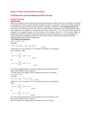
Bottom reinforcement
Generally
(3.71)
If either Mx* or My * in equations (3.71) is found to be negative, it is changed to
zero, as follows: either
or
(3.72)
Or
(3.73)
If, in these changed formulae, the wrong algebraic sign results for Mx* or My* ,
then no such reinforcement is required.
If bothMx* and My* are negative, then no bottom reinforcement is required.
Top reinforcement
Generally
(3.74)
If either Mx * or My * in equations (3.74) is found to be positive, then change to
either
(3.75)
or
(3.76)
If, in these changed formulae, the wrong algebraic sign results for Mx* or My* ,
then no such reinforcement is required.
If both Mx* and My* are negative then no top reinforcement is required.
2. Example – simply supported slab design moments
Referring to Fig. 3.16, the design moments at various points of the simply supported
slab considered previously may be evaluated as follows:
At centre (C): Mx = My = +0.023qL2, Mxy = 0
Bottom reinforcement: Mx* = My* = +0.023qL2
Top reinforcement: Mx* = My* = 0
At quarter point (1): Mx = My = +0.009qL2, Mxy = –0.011qL
Bottom reinforcement: Mx* = My* = +0.020qL2
Top reinforcement: Mx* = My* = –0.002qL2
At corner (A): Mx = My = 0, Mxy = –0.019qL2
Bottom reinforcement: Mx* = My* = +0.019qL2
Top reinforcement: Mx* = My* = –0.019qL2
From the above, it may be seen that top (torsional) reinforcement is only required
close to the corners, as would be expected, and that the bottom reinforcement
requirements at the centre and corners are rather similar. Naturally,
much less bottom steel is needed close to the centre point of an edge.
Example 3.8 – fixed-edge slab design moments
Fig. Fixed-edge slab: (a) reference plan of quarter slab; (b) w (x 10–3qL4/D);
(c) Mx (x 10–2qL2); (d) Mxy (x 10–2qL2); (e) Qx (x 10–1qL); (f) Vy (x 10–1qL)
With reference to Fig., the design moments will be calculated at point D, not because this is a particularly
critical slab location, but simply to illustrate the application of the design moment computations:
At point D: Mx = –0.008qL2; My = +0.002qL2; Mxy = –0.005qL2
Bottom reinforcement: Mx * = –0.003qL2; My * = +0.007qL2
So take equation (3):Mx * = 0;My * = (+0.002 + 0.0052/0.008)qL2 = +0.005qL2
Note that the subsidiary calculation results in some moment reduction but that this will be small if the design
moment with the offending sign was also small.
Top reinforcement: Mx * = –0.013qL2; My * = –0.003qL2.