Download to read offline
![International Research Journal of Engineering and Technology (IRJET) e-ISSN: 2395-0056
Volume: 04 Issue: 07 | July -2017 www.irjet.net p-ISSN: 2395-0072
© 2017, IRJET | Impact Factor value: 5.181 | ISO 9001:2008 Certified Journal | Page 3094
Analytical study on Flexural behaviour of RCC slabs with concealed
beams using ANSYS
Mahmad Irfan Nadagouda1, Dr.G.Ravi2
1 M.tech student, Department of Civil Engineering, The National Institute of Engineering, Mysore,Karnataka,India
2 Professor, Department of Civil Engineering, The National Institute of Engineering, Mysore,Karnataka,India
---------------------------------------------------------------------***---------------------------------------------------------------------
Abstract - When the beam depth is equal to the thickness of
slab that beam is known as concealed beam. Concealedbeams
are favoured structural elements because of their many
inherent features that characterize them; they save on floor
height clearance, formwork material costandshutteringtime.
Moreover, they form an acceptable aesthetic appearance. The
present study deals with the finite element modelling of RC
slabs with concealed beam & with drop beams using ANSYS,
which is based on Finite Element (FE) method. The flexural
behaviour of slabs with the influence of concealed beams is
investigated. The results of the slabs from the analytical
solution are compared with the available experimental
results. Comparison between load deflection curve, Crack
pattern & load carrying capacity were carried.
Key Words: Concealed beam, drop beam, Load-deflection,
Load carrying capacity, crack pattern, Finite Element,
ANSYS.
1. INTRODUCTION
Slabs are constructed to provide flat surfaces, usually
horizontal, in building floors, roofs, bridges, and other types
of structures. In many situations, the architect may want to
have a flat soffit of slab, without beams projecting out of the
slab. In such situations, the structural engineer has to resort
to concealed beams. Modern buildings have manystructural
constraints. The web of a T beam or inverted T beam may
pose problems. In such situations, Concealed beams may be
provided. This performs the functionofa conventional beam
to a great extent. Concealed beams in particulararerequired
in drop free slabs. The beams of same depth as slab are
placed as usual with exception of formwork of side or
bottom. Nowadays, for nonlinear analysis of RC members,
finite element (FE) analysis has become an important
analytical tool. The FE method allows complex analysis of
nonlinear response of RC structures to be carried out in
understanding its behaviour under different loading
conditions.
The present study deals with the finite element modelling of
RC slabs with concealed beam & with drop beams using
ANSYS. The validation of FE analysis has been verified using
the experimental results. The aim of the study is to
understand the structural performance of the slabs built in
with concealed beams and drop beams.
2. RESEARCH SIGNIFICANCE
Execute a 3D Finite Element Model in order to investigate
the influence of concealed beam in slabs replacing the
conventional structural system of drop beam. Analysis of
simply supported slabs with two grades of concrete M25 &
M30 to study the importance of grade of concreteonflexural
behaviour of slabs. Lastly to check the validity and accuracy
of the finite element analysis used in this study to predict
the flexural behaviour of the slabs.
3. METHODOLOGY FOR FINITE ELEMENT
MODELLING AND ANALYSIS USING ANSYS
The experimental method of analyzing the RC slabs
provides the actual behaviour of the structure. But it is time
consuming and expensive. Hence Finite element analysis is
used to analyze these structural components.FiniteElement
Analysis (FEA) is a method used for the evaluation of
structures, providing an accurate prediction of the
component’s response subjected to various loads.Theuseof
FEA has been the preferred method to study the behaviour
of structural component as it is much faster than the
experimental method andis costeffective. The finite element
method is an approximate technique. The number of
elements used in a model can greatly affect the accuracy of
the solution.
The details & results of experimental work
conducted by Sharanbasappa kembhavi (2016) [6]hasbeen
utilised in the present study. The experimental work was
conducted on 12 specimens, 3 specimenseachwithdifferent
beam and concrete grade configuration. The average result
of the three specimens was recorded. The same data has
been used in the present analytical study as reference.
Table-1 Details of specimens
Specim
en
design
ation
Type of
slab (with)
Dimensions (mm) Grade
of
concret
e
Grade
of
Steel
Slab Beam
Type-A
concealed
beam 1000x1800x75 200x75 M25 Fe 500
Type-B
concealed
beam 1000x1800x75 200x75 M30 Fe 500
Type-C
drop beam
1000x1800x75 200x150 M25 Fe 500
Type-D
drop beam
1000x1800x75 200x150 M30 Fe 500](https://image.slidesharecdn.com/irjet-v4i7622-170914100048/75/Analytical-Study-on-Flexural-Behaviour-of-RCC-Slabs-with-Concealed-Beams-using-ANSYS-1-2048.jpg)
![International Research Journal of Engineering and Technology (IRJET) e-ISSN: 2395-0056
Volume: 04 Issue: 07 | July -2017 www.irjet.net p-ISSN: 2395-0072
© 2017, IRJET | Impact Factor value: 5.181 | ISO 9001:2008 Certified Journal | Page 3100
Table 7 Comparison of Analytical loads with experimental
Loads
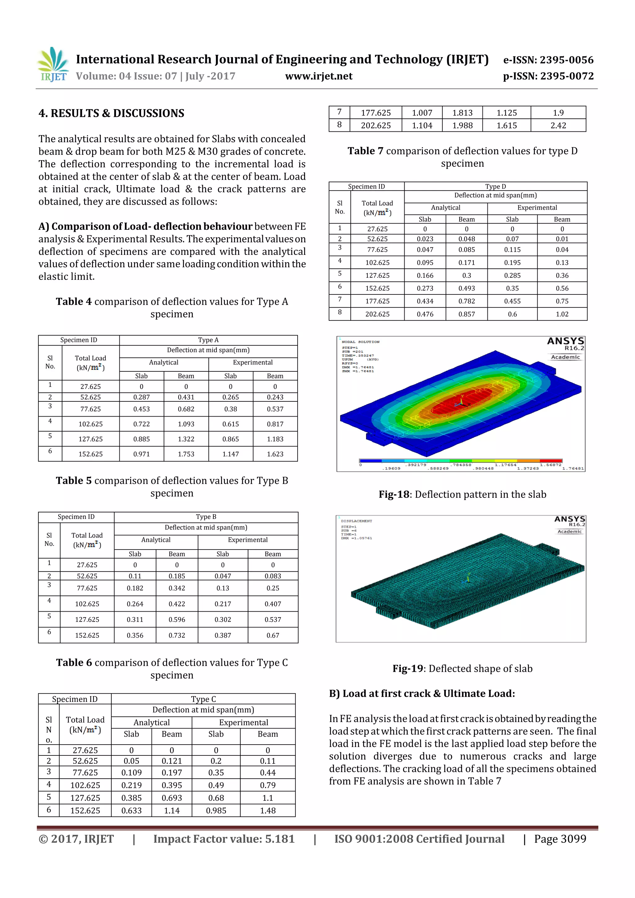
C) Crack pattern:
In FE analysis concrete crack patterns were created at
different load steps to examine the different types of
cracking that occurred within the concrete. The ANSYS
program records a crack pattern at each applied load step.
Figure 20 and 21 shows the crack patterns observed in the
analytical model of the Specimens. It is observed that, the
crack patterns obtained from the analytical studyare similar
to that of crack patterns observed during experimental
study. The cracks appear at the junction between the slab
and the beam, further it propagates all along the length of
the beam.
Fig-20: Comparison of crack pattern in slab with
concealed beam
Fig-21: Comparison of crack pattern in slab with drop
beam
5. CONCLUSIONS
The conclusions drawn from the analytical investigation
are listed below,
1. The behaviour of RC slabs represented by load
deflection curves in ANSYS show close agreement
with experimental results, within the linear part
before first cracking.
2. The deflection of slabs with concealed beamismore
compared to that of drop beams. This is due to the
reduction in cross section area & thus reducing the
stiffness.
3. As the grade of concrete increases the deflection in
the slab reduces, hence grade of concrete plays
important role in reducing the deflection.
4. Analytically, the load carrying capacity of slab with
drop beam increases by 26.63% as compared to
that of slab with concealed beam & experimentally
it was increased by 27.2%. The FE analysis results
were in good agreement.
5. The ultimate loads from the FE analysis are slightly
greater than the ultimate loads from the
experimental results, due to the presence of initial
micro cracks in the experimental models,
instability issues of load mechanism adopted in
the experimental setup
6. The experimental deflection is 21.2% more than
that of analytical deflection in slab with concealed
beam, due to the increased stiffnessoftheFEmodel.
7. The experimental deflection is 17.8% more than
that of analytical deflection in slab with drop beam.
8. Analytically, the maximum deflection of slab with
drop beam has decreased by 32% as compared to
the slab with concealed beam. This is due to the
increased stiffness & increasedmomentofinertia of
slab with drop beam.
5.REFERENCES
[1] IS: 456-2000 “Plain AndReinforcedConcrete-Code
Of Practice”, Bureau of IndianStandards,NewDelhi,
2000.
[2] Ibrahim Mohammad Arman, “Analysis of Two Way
Ribbed and Waffle Slabs With Concealed Beams”.
International Journal of Civil and Structural
Engineering Volume 4, No 3, 2014.
[3] Samir H.Helou, Munther M. Diab, “Slabs With
Concealed Beams Facts And Fallacies”. Asian
Journal of Engineering and Technology (ISSN: 2321
– 2462) Volume 02 – Issue 04, August 2014.
[4] Samir H. Helou and Riyad Awad “Performance
Based Analysis of Concealed Beams in Reinforced
Concrete Structures”. MATEC web of conferences,
2014
[5] Ziad N. Taquieddin, “Deflection Of Wide Concealed
Beams In One Way Slab Systems: A nonlinear Finite
Sl No. Specimen ID
EXPERIMENTAL ANALYTICAL
First crack load
(kN/m)
Ultimate load
(kN/m)
First crack load
(kN/m)
Ultimate load
(kN/m)
1 Type A 29.167 80.525 32.54 83.409
2 Type B 34.692 88.025 35.17 94.976
3 Type C 40.525 110.525 41.32 113.685
4 Type D 48.025 120.525 50.21 124.259](https://image.slidesharecdn.com/irjet-v4i7622-170914100048/75/Analytical-Study-on-Flexural-Behaviour-of-RCC-Slabs-with-Concealed-Beams-using-ANSYS-7-2048.jpg)
![International Research Journal of Engineering and Technology (IRJET) e-ISSN: 2395-0056
Volume: 04 Issue: 07 | July -2017 www.irjet.net p-ISSN: 2395-0072
© 2017, IRJET | Impact Factor value: 5.181 | ISO 9001:2008 Certified Journal | Page 3101
Element Study”. Journal of Institute of research
engineers and doctors 2014.
[6] Sharanbasappa Kembhavi, “Studies on flexural
behaviour of rcc slabs with concealed beams” A
M.Tech dissertation work in structural engineering,
submitted at NIE Mysuru, June 2016.
[7] ANSYS, Inc. “ANSYS Mechanical APDL Theory
Reference” ANSYS, Inc. Release 15.0 November
2013.
[8] Shatha S. Kareem et al,” Nonlinear FE Modelling of
Two-Way Reinforced Concrete SlabofNSC,HSCand
LWC under Concentrated Load” Journal of
Engineering and Development, Vol. 17, No.2, 2013,
ISSN 1813‐ 7822
[9] Mustafa Basheer Mahmood , V. C. Agarwal, “Non-
Linear Finite Element Analysis of RC Slabs
Strengthened with CFRP Laminates” International
Journal of Engineering Trends and Technology
(IJETT) – volume 5 number 3- Nov 2013
[10] MohamedKandil,“FiniteElementModeling
ofHighStrengthReinforcedConcreteSlabs”,Proc.of
the Intl. Conf. on Advances In Civil, Structural And
Construction Engineering - CSCE 2014.
[11] Sheetal Gawas and Dr. S.V.Itti, “Study
ontwo way RC Slab using ANSYS with and without
central opening” International Journal of Scientific
Engineering and Technology (ISSN: 2277-1581)
Volume No.3 Issue No.8, Aug 2004
[12] V.S Jagadeesh, D.S Parkash and Vahini. M,
“Analysis Of Concealed Beams”,(SEWC 2007).](https://image.slidesharecdn.com/irjet-v4i7622-170914100048/75/Analytical-Study-on-Flexural-Behaviour-of-RCC-Slabs-with-Concealed-Beams-using-ANSYS-8-2048.jpg)

This document presents a finite element analysis of reinforced concrete slabs with concealed beams and drop beams using ANSYS software. The study aims to understand the structural performance of slabs with concealed beams compared to drop beams. A 3D finite element model was created to analyze simply supported slabs with M25 and M30 concrete grades. The load-deflection behavior, crack patterns, and load carrying capacity from the finite element analysis were compared to experimental results to validate the accuracy of the finite element model.


