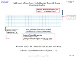
This document presents a nonlinear finite element analysis of a notched unreinforced concrete beam tested by Petersson in 1981. A medium mesh model from an Abaqus example was used to model the beam in MSC/Marc. The analysis found the load-deflection curve computed in MSC/Marc was stiffer than the experimental results, similar to results from Abaqus/Standard which also uses a linear tension softening assumption. The document provides details on the beam geometry, material properties, and compares the load-deflection curves from the analysis to the experimental test data.
![Introduction
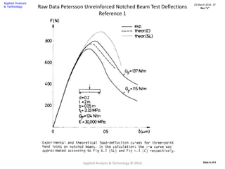
Petersson, P.E (1.) tested an unreinforced notched concrete beam in 1981.
[Ref. Figure 8.16 Experimental and theoretical load-deflection curves for three-point bend tests on
notched beams.] See Slide 8.
The purpose of this summary is to present results of addressing this Notched
Unreinforced Concrete Beam and computing the load deflection curve using MSC/Marc
for comparison to the experimental test data at the nominal fracture toughness, Gf = 124
N/m.
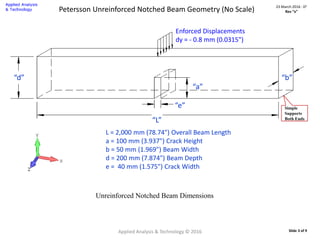
For purposes of this analysis a medium mesh model definition was borrowed from an
Abaqus example problem “3.2.11 Notched unreinforced concrete beam under 3-point
bending”. (2.)
Since Marc uses a linear tension softening modulus, Es, results from Abaqus/Standard
with linear tension softening are used for comparison. [Ref. Figure 3.2.11-6 Plane stress
Abaqus/Standard mesh refinement study – medium mesh.]
Note: As noted in the Abaqus example, when linear tension softening is assumed in the
Abaqus solution, this leads to a response that is overly stiff compared with the
experimental observations of Petersson.
Applied Analysis & Technology © 2016
23 March 2016 : D2
Rev “x”
Slide 2 of 9](https://image.slidesharecdn.com/c24130c1-197e-40c9-88bc-ba63996922c6-160907154216/85/Analysis-Petersson-NotchedBeam-MSC-Marc-2-320.jpg)
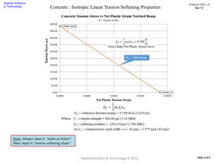
![Concrete : Isotropic Properties
The concrete is idealized using 2D Plane Stress elements. Young’s modulus of elasticity for the concrete is given as:
Concrete Material Properties
Elastic : Ec= 4.35 x10⁶ psi ν = 0.20
Cracking : Critical Cracking Stress (Rupture Stress) fr = 482.96 psi
Softening Modulus, Es= 259,410 psi [Failure Strain = 0.00197 in/in]
Crushing Strain, εc = 0.005 in/in, Shear Retention : 7.5%
Concrete Isotropic Material Input Dialog
Applied Analysis & Technology © 2016
23 March 2016 : D2
Rev “x”
Slide 6 of 9](https://image.slidesharecdn.com/c24130c1-197e-40c9-88bc-ba63996922c6-160907154216/85/Analysis-Petersson-NotchedBeam-MSC-Marc-6-320.jpg)