Downloaded 275 times
![3
T sin dθ = mω2
l sin dθ
T = mω2
l ……..(3)
From (1) and (3)
mg = mω2
l
ω2
= (g / l) ;ω = √(g/l)
we have ; ω = 2 π / T
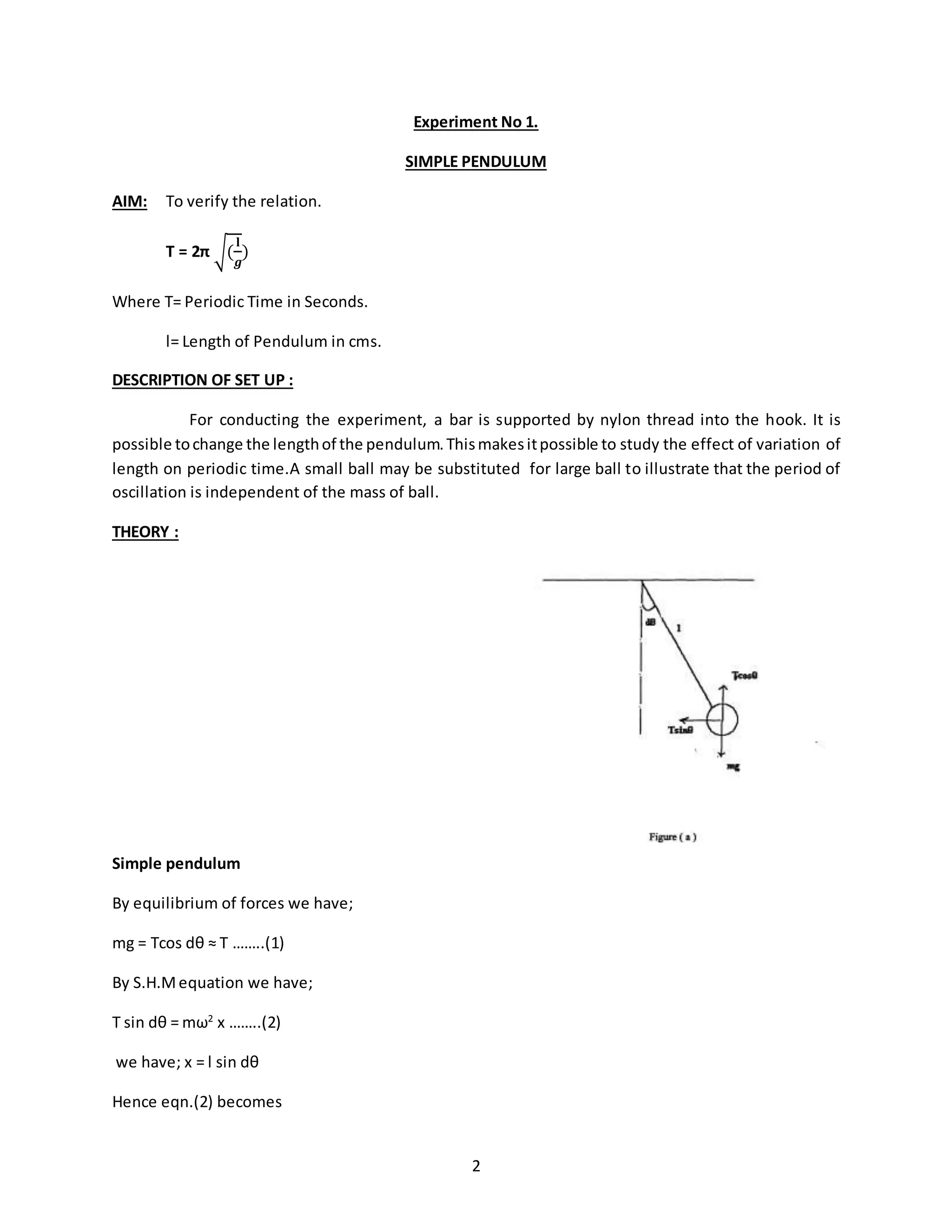
Hence,T = 2π √(
l
𝑔
)
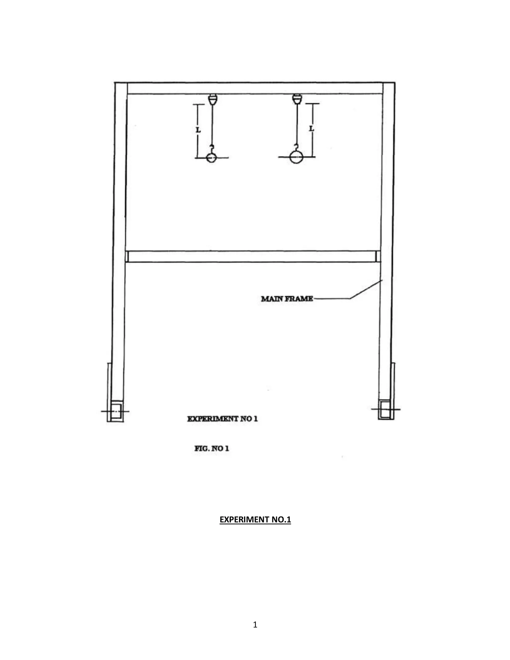
PROCEDURE:
a] Attach each ball to one end of the thread.
b] Allowthe ball tooscillate anddeterminethe periodictime Tbyknowingtime (forsay 10 oscillations).
c] Repeat the experiment by changing the length.
d] Complete the observation table given below.
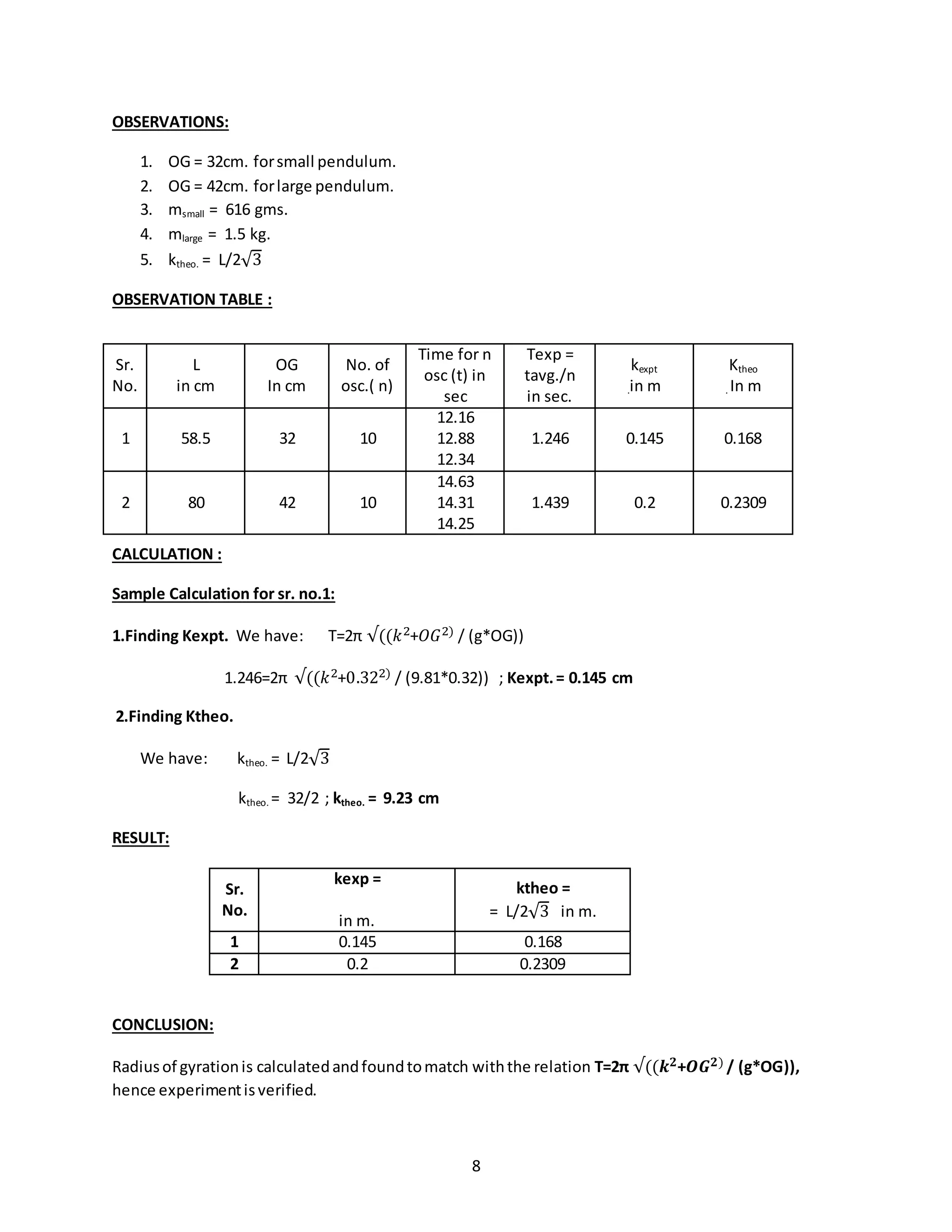
OBSERVATIONS:
Weight of small ball: 112 gms.
Weight of largel ball: 60 gms.
OBSERVATION TABLE :
Sr.No.
Mass of the ball
(m) in gms.
Length
(L) In cms.
No.of osc.
(n)
Time for n
oscillation (t) in
sec.
Texp =
t avg./ n in
sec.
Ttheo =
2π √(
𝐥
𝒈
)
in sec.
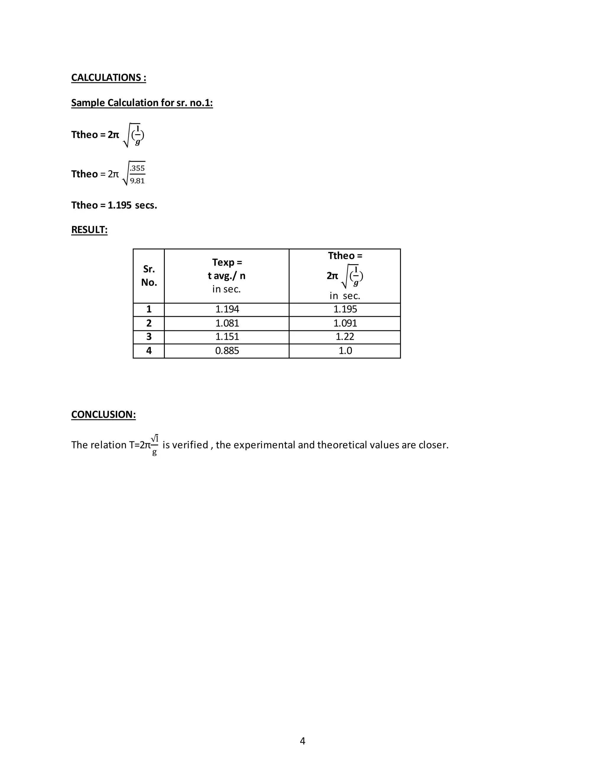
1 112 35.5 10
11.82
11.95
12.06
1.194 1.195
2 112 29.5 10
10.75
10.79
10.90
1.081 1.091
3 60 37 10
11.44
11.59
11.49
1.151 1.22
4 60 25 10
8.41
8.66
8.50
0.885 1](https://image.slidesharecdn.com/allexperiments-1-150330000251-conversion-gate01/75/All-experiments-1-3-2048.jpg)
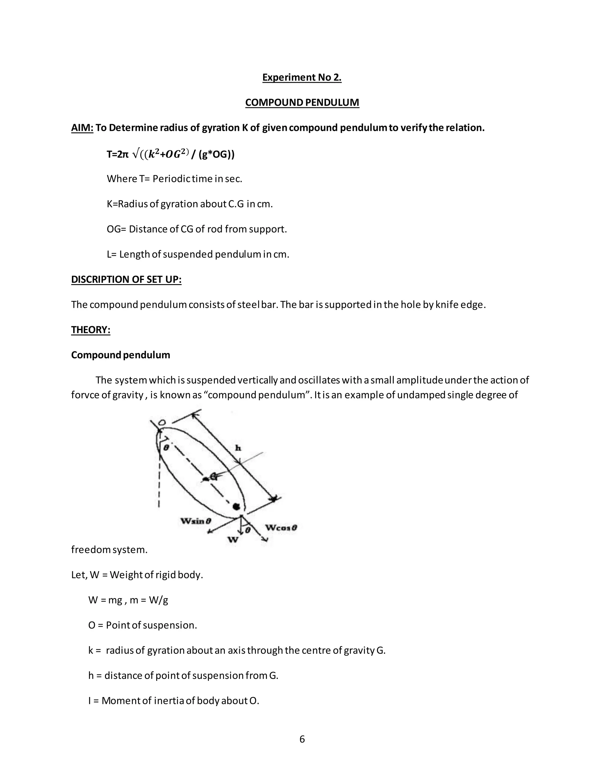
![7
= m𝑘2 + 𝑚ℎ2
If OG isdisplacedbyanangle ‘θ’, restoringtorque T.
T = -h W sinθ
= -mghsinθ
If θ isverysmall,thensinθ= θ , thenabve equationcanbe writtenas,
T = -mghθ
Inertiatorque isgivenas,
T = -I θ
Summingupall momentsactingonthe body,
Iθ + mgh = 0
The natural frequencyωn canbe determinedas
ωn = √(
𝑚𝑔ℎ
𝐼
)
also,
ωn = √(
𝑚𝑔ℎ
𝑚𝑘²+𝑚ℎ²
)
ωn = √
𝑔ℎ
𝑘²+ℎ²
fn =
1
2𝛑
√
𝑔ℎ
𝑘²+ℎ²
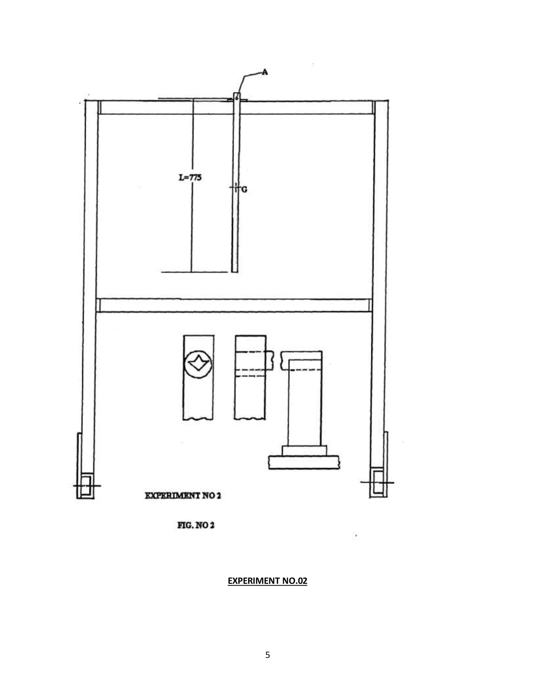
PROCEUDRE:
1] Supportthe rod knife edge.
2] Note the lengthof suspendedpendulumanddetermine OG.
3] Allow the barto oscillate and determine‘ T ’ byknowingtime for10 oscillations.
4] Repeatthe above procedure withthe secondpendulum.
5] Complete the observationtable givenbelow.](https://image.slidesharecdn.com/allexperiments-1-150330000251-conversion-gate01/75/All-experiments-1-7-2048.jpg)
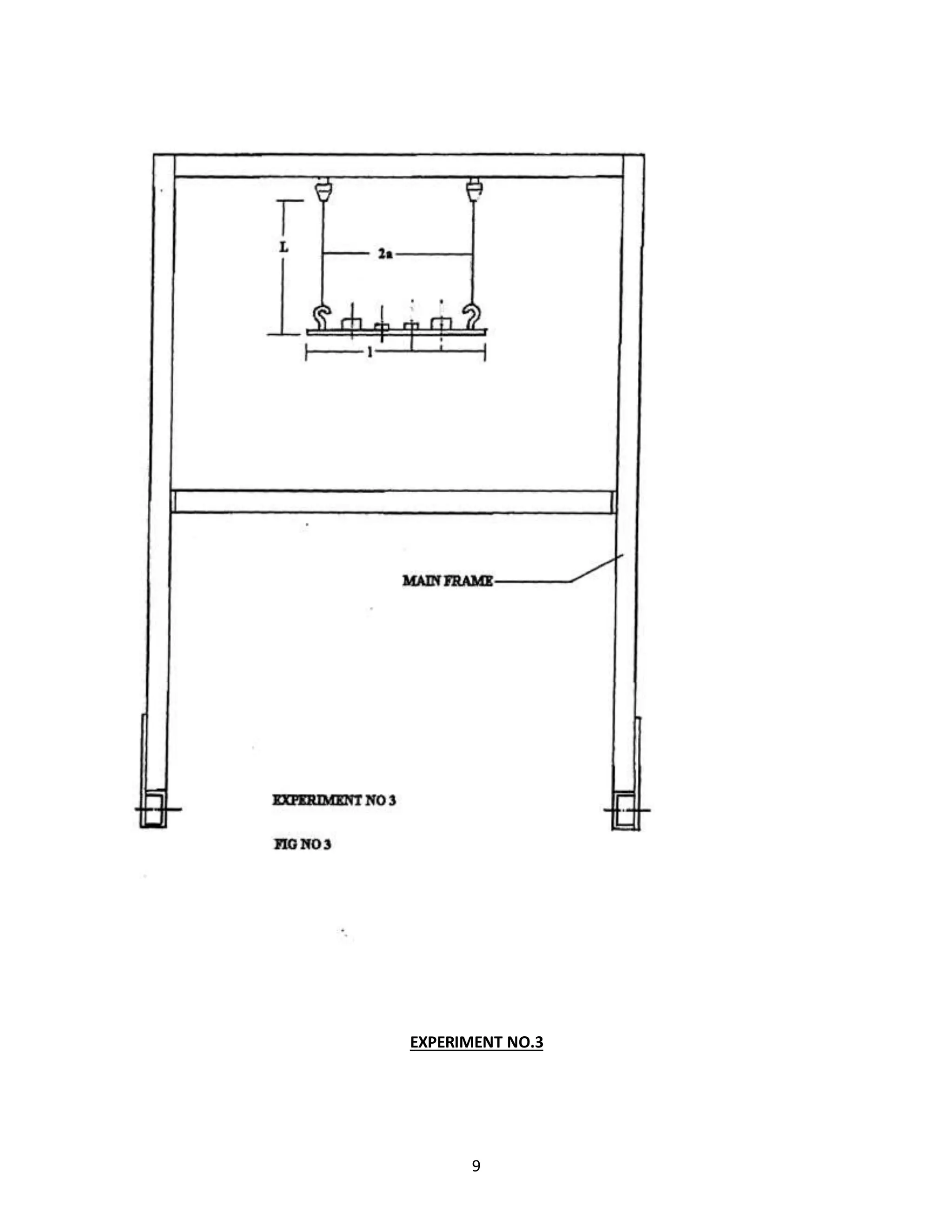
![11
From the geometry
l1Ɵ = l Φ1 and l2Ɵ = l Φ2
or Φ1 = l1Ɵ / l , Φ2 = l2Ɵ / l ………………(2)
The resisting torque T for the system can be written as
T = TA l1 Φ1 +TB l2 Φ2
=[(Wl2)/(l1 + l2) ]*[(( l1Ɵ) / l)]*l1 + [(Wl1)/(l1 + l2)]*[(( l2Ɵ) / l)]*l2
Substituting TA and TB from (1) and Φ1and Φ2 from (2)
= [(W l2 l1 Ɵ) /(l1 + l2)l]*[( l1 + l2)]
= (W l2 l1 Ɵ)/ l ………..(3)
We know that
T = I α
Where , T = torque
I = Moment of inertia = W k2
/ g
α = angular acceleration
k = radius of gyration
So, α = T/I
= ( (W l2 l1 Ɵ)/ l)/ (W k2
/ g)
= (g l2 l1 Ɵ) / l k2
……….(4)
We also know that
ω2
= Angular acceleration / Angular Displacement
Where, ω = Angular velocity of AB
ω2
= (g l2 l1 Ɵ) / l k2
θ
ω2
= (g l2 l1 ) / l k2](https://image.slidesharecdn.com/allexperiments-1-150330000251-conversion-gate01/75/All-experiments-1-11-2048.jpg)
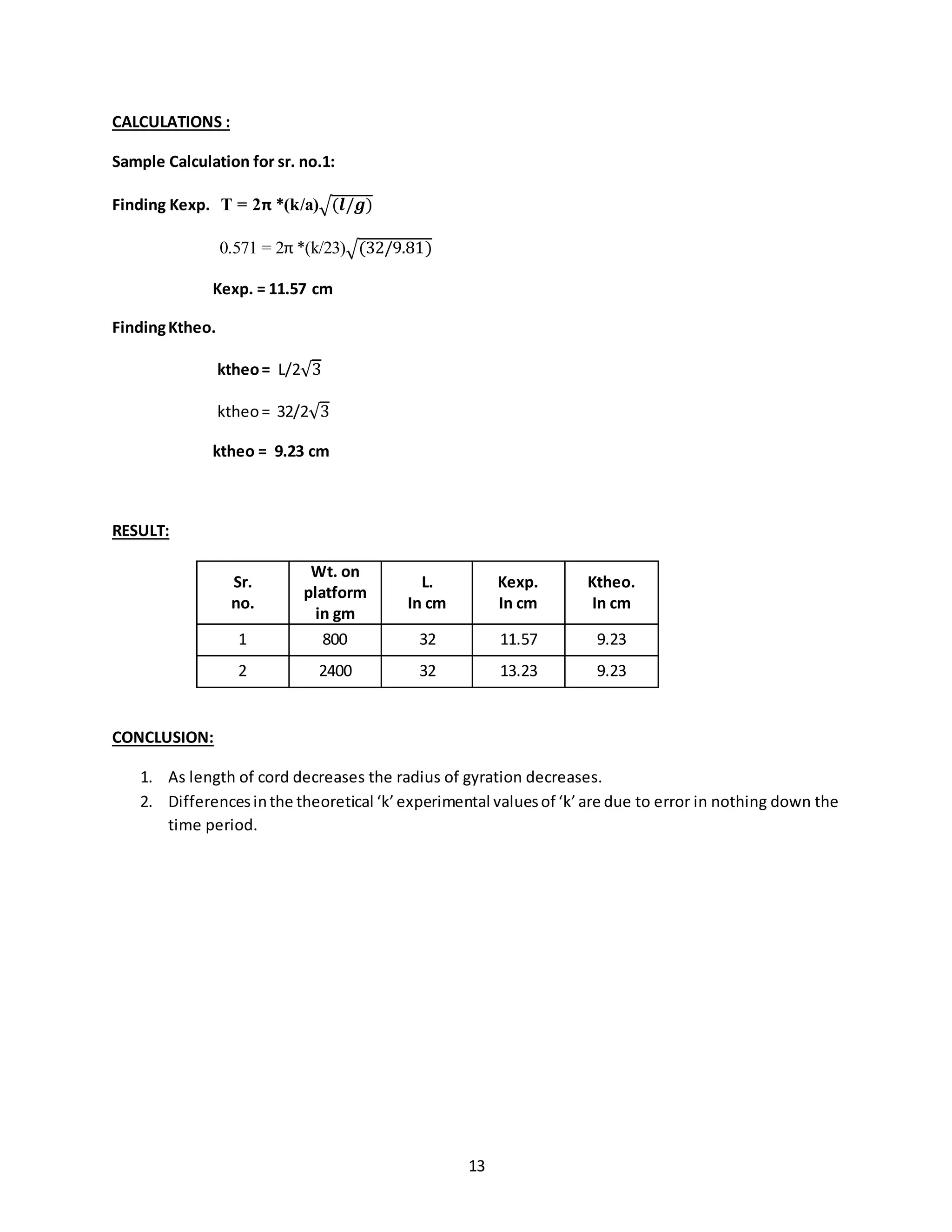
![12
Here, l2 = l1= a
ω2
= (g a2
) / l k2
ω = (a/k)√(𝑔/𝑙)
We have ω = 2π/T
Hence T = 2π *(k/a)√(𝒍/𝒈) ………(5)
PROCEDURE:
1] Suspendthe bar formhook.The suspensionlengthof each cord mustbe the same.
2] Allowthe barto oscillate aboutthe vertical axispassingthroughthe center&measure the periodic
time‘t’byknowingtime sayfor10 oscillations.
3] Repeatexpt.bymountingthe weightatequal distance formcenter.
4] Complete the observationtable.
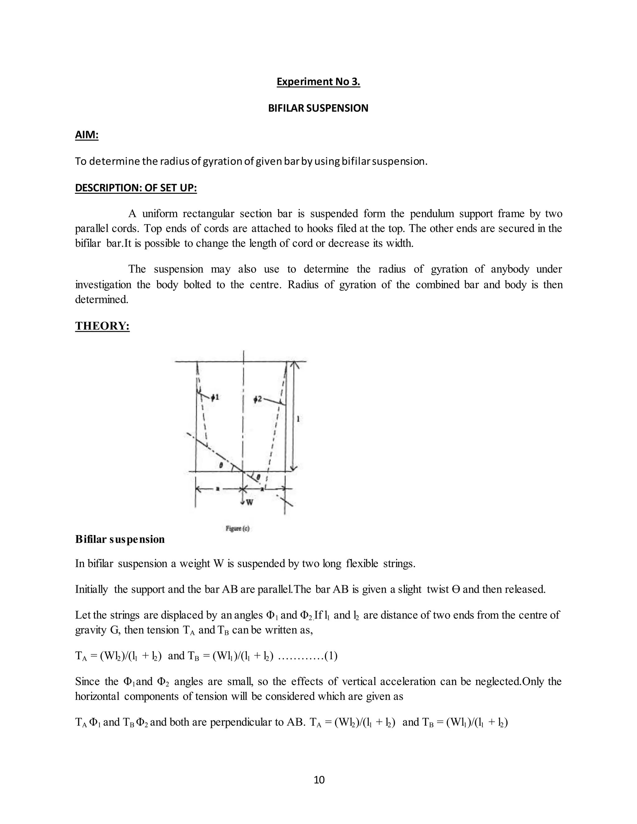
OBSERVATIONS:
Weightonthe platform:800 gms
OBSERVATION TABLE :
Sr.
no.
Wt. on
platform
In gms.
L
In cm
a
in cm
t
in
sec
No. of
oscillations
n
T =
tavg/n
In sec
Kexp.
In cm
ktheo =
= L/2√3
in m.
In cm
1 800 32 43
5.56
5.66
5.91
10 0.571 11.57 9.23
2 2400 32 43
5.56
6.5
6.53
10 0.65 13.23 9.23](https://image.slidesharecdn.com/allexperiments-1-150330000251-conversion-gate01/75/All-experiments-1-12-2048.jpg)
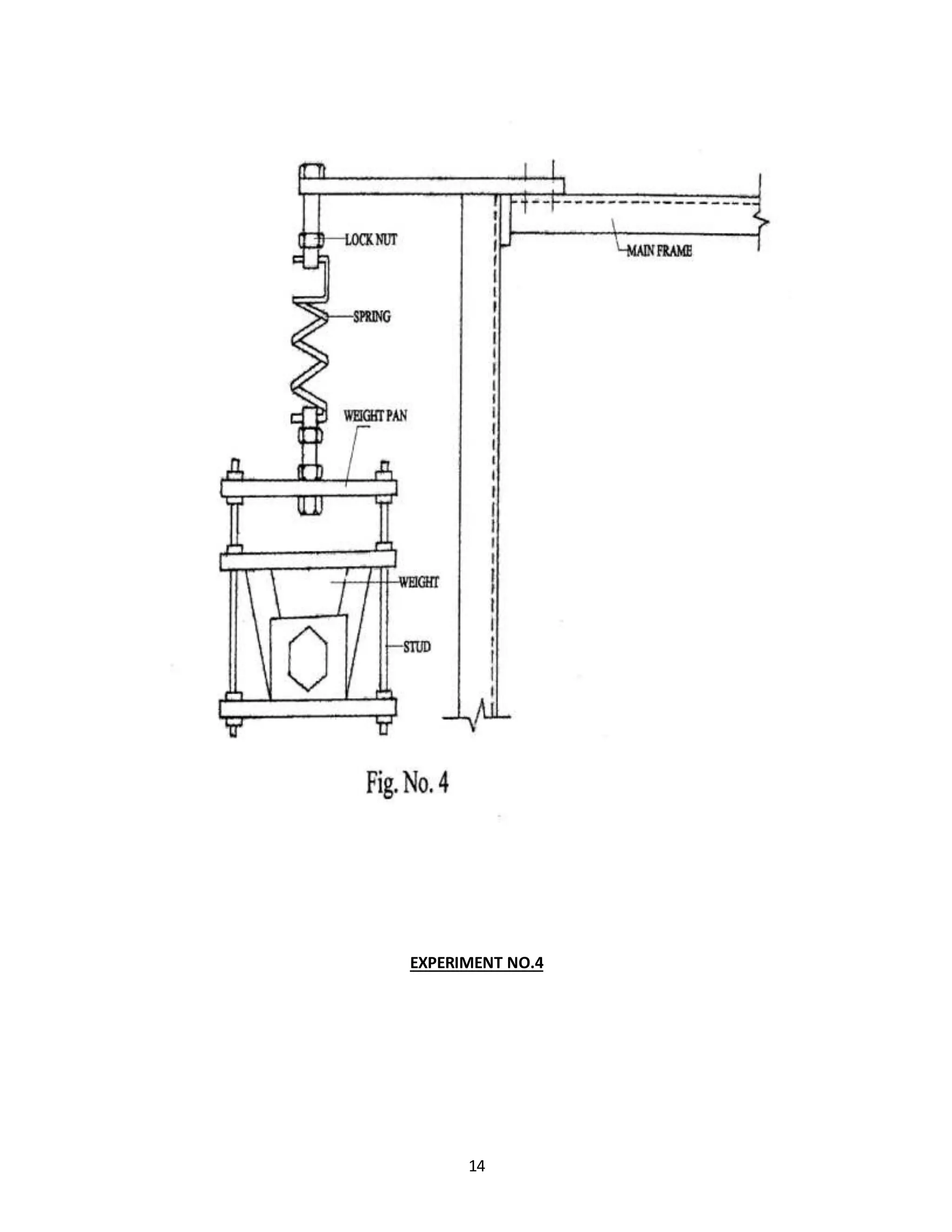
![15
Experiment No 4
LOGITUDINAL VIBRATION OF HELICAL SPRING
AIM:
To studythe longitudinal vibrationof helical springandtodetermine frequencyorperiodof vibration
(oscillation) theoreticallyandactuallybyexperiment.
DESCRIPTION OF SET UP :
One endopencoil spring isfixedtothe screw can be adjusted vertically in any convenient position and
then clamped to upper beam by means of lock nuts. Lower end of spring is attached to the platform
carryingweights. Thus design of system incorporates vertical positioning of the unit to unit to suit the
convenience.
PROCEDURE:
1] Fix one end of vertical spring to the upper screw.
2] Determine free length.
3] Put same weight to platform and down deflection.
4] Stretch the spring through some distance & release.
4] Count the time required (in sec) for some say 10,20, oscillation.
5] Determine the actual period.
6] Repeat the procedure for different weight.](https://image.slidesharecdn.com/allexperiments-1-150330000251-conversion-gate01/75/All-experiments-1-15-2048.jpg)
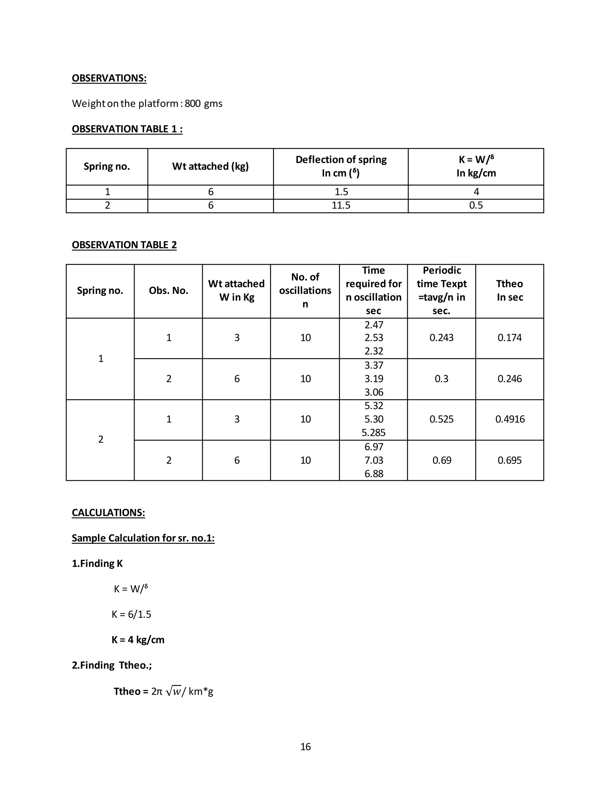
![17
Ttheo = 2π √3/ 4*9.81
Ttheo = 0.174 sec.
3.Finding ftheo. and fexpt..;
ftheo. = 1/ Ttheo
ftheo. = 1/ 0.174
ftheo. = 5.74 cps
fexpt. = 1/ Texpt
fexpt. = 1/ 0.243
fexpt. = 4.115cps
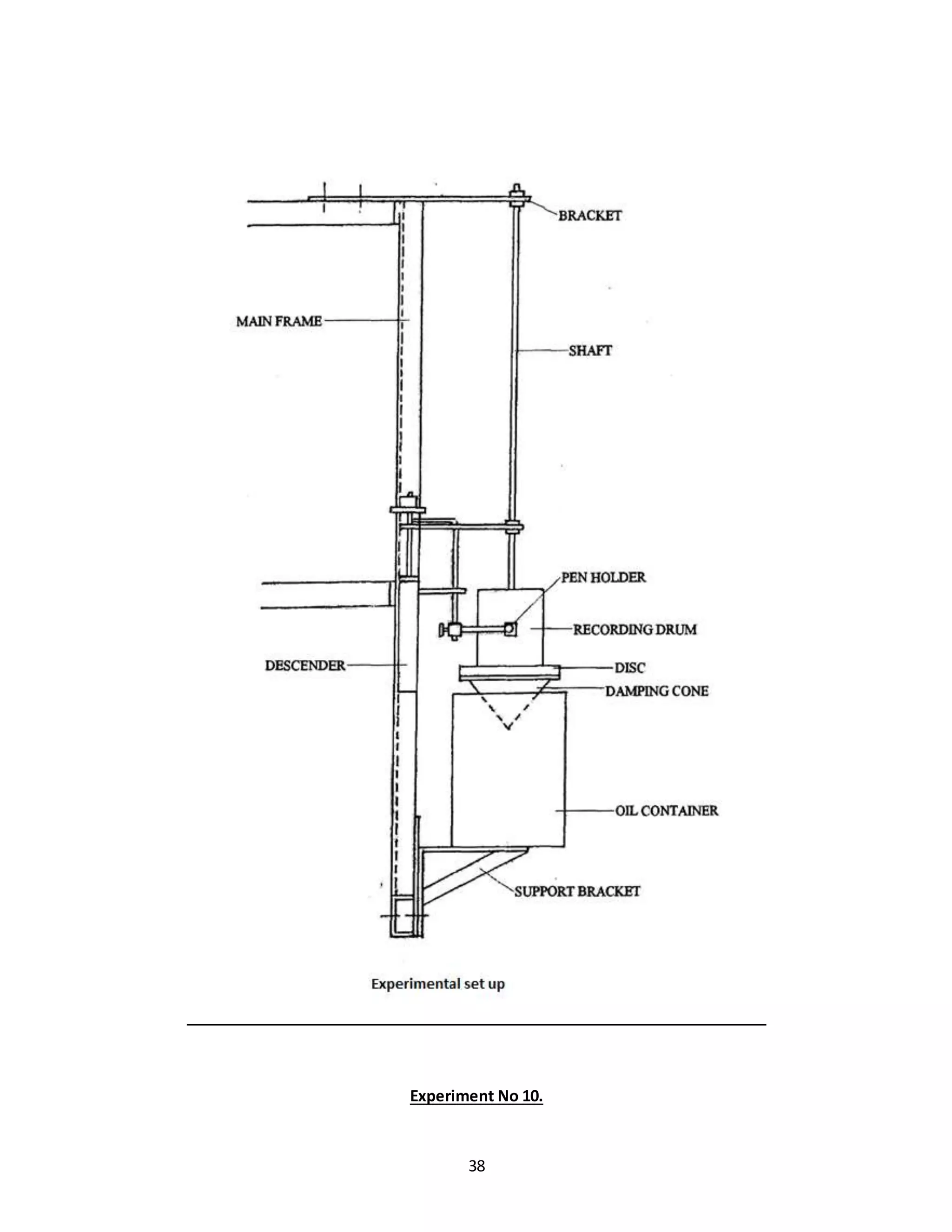
RESULT:
For Spring wt.in kg Experimental Theoretical
F in cps F in cps
1 3 4.115 5.74
2 6 3.33 3.33
3 3 1.904 1.904
4 6 1.449 1.449
CONCLUSION:
The difference in F expt & F theoretical is due to
1] Observation human error
2] Damping effect of air.](https://image.slidesharecdn.com/allexperiments-1-150330000251-conversion-gate01/75/All-experiments-1-17-2048.jpg)

![23
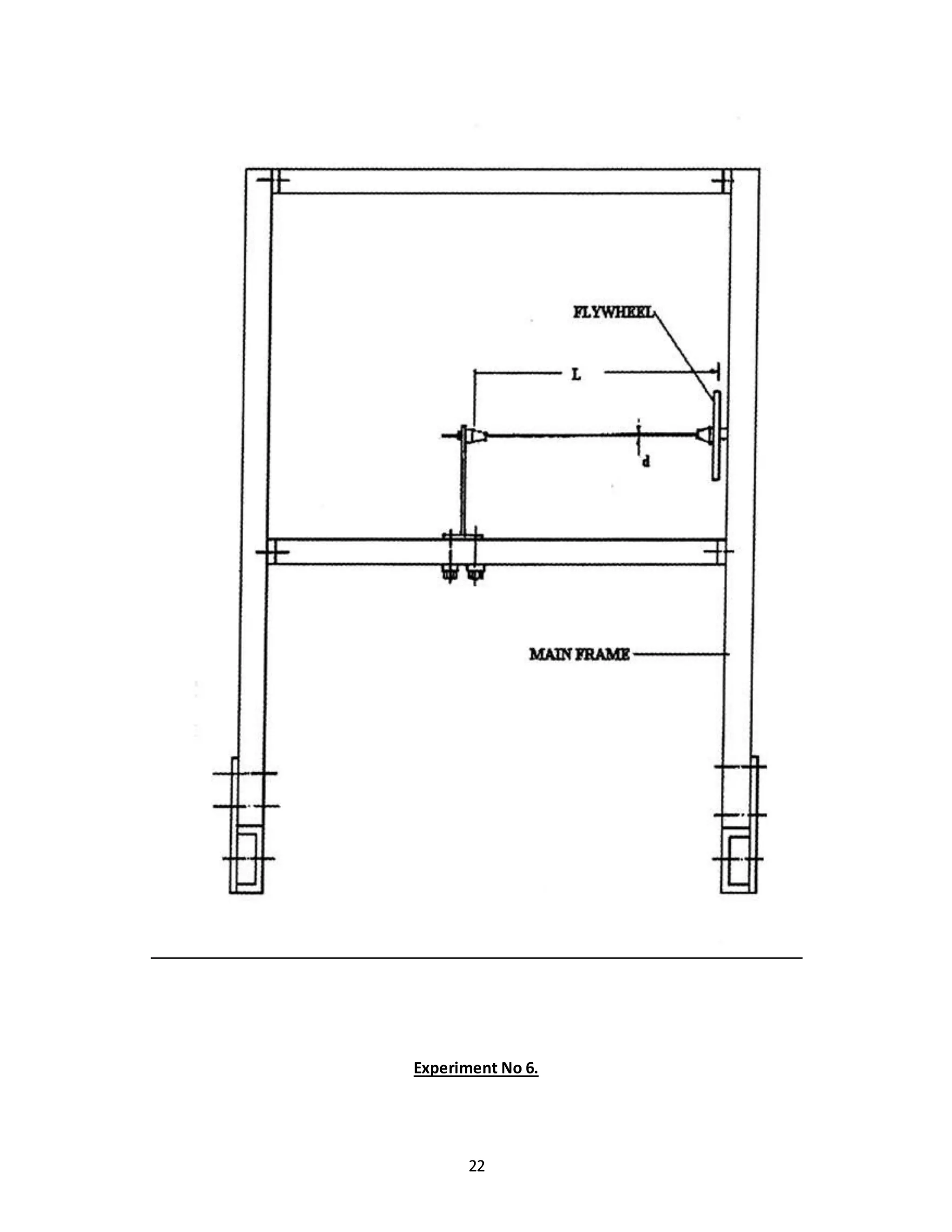
Experiment No 6.
UNDAMPED TORSIONAL VIBRATION OF SINGLE ROTOR SHAFT SYSTEM
AIM: To studyundampedtorsional vibrationof singlerotorshaftsystem.
DISCRIPTION OF SET UP:
The arrangementisan showninfigone endof shiftisgrippedindule anda flywheel freetorotate in
ball bearinginfixedtootherendof shaft.
The bracket withfixedendshaftcanbe convenientlydampedatanypositionalongbeam.Thuslengthof
shaftcan be variedduringexperiment,especiallydesigned b chucks are used for clamping end of shaft.
The ball bearingsupportto flywheel providesnegligible acting support during experiment. The bearing
housing is fixed to side member of main frame.
PROCEDURE:
1] Fix bracketat convenientpositionalongleverbeam.
2] Grip one endof shaftat bracketby meansof chucks.
3] Fix rotor ontothrough endof shaft.
4] Twistthe rotor through semi cycle andrelease.
5] Note downtime requiredfor10 oscillations.
6] Repeatprocedure fordifferentlengthof shaft.](https://image.slidesharecdn.com/allexperiments-1-150330000251-conversion-gate01/75/All-experiments-1-23-2048.jpg)
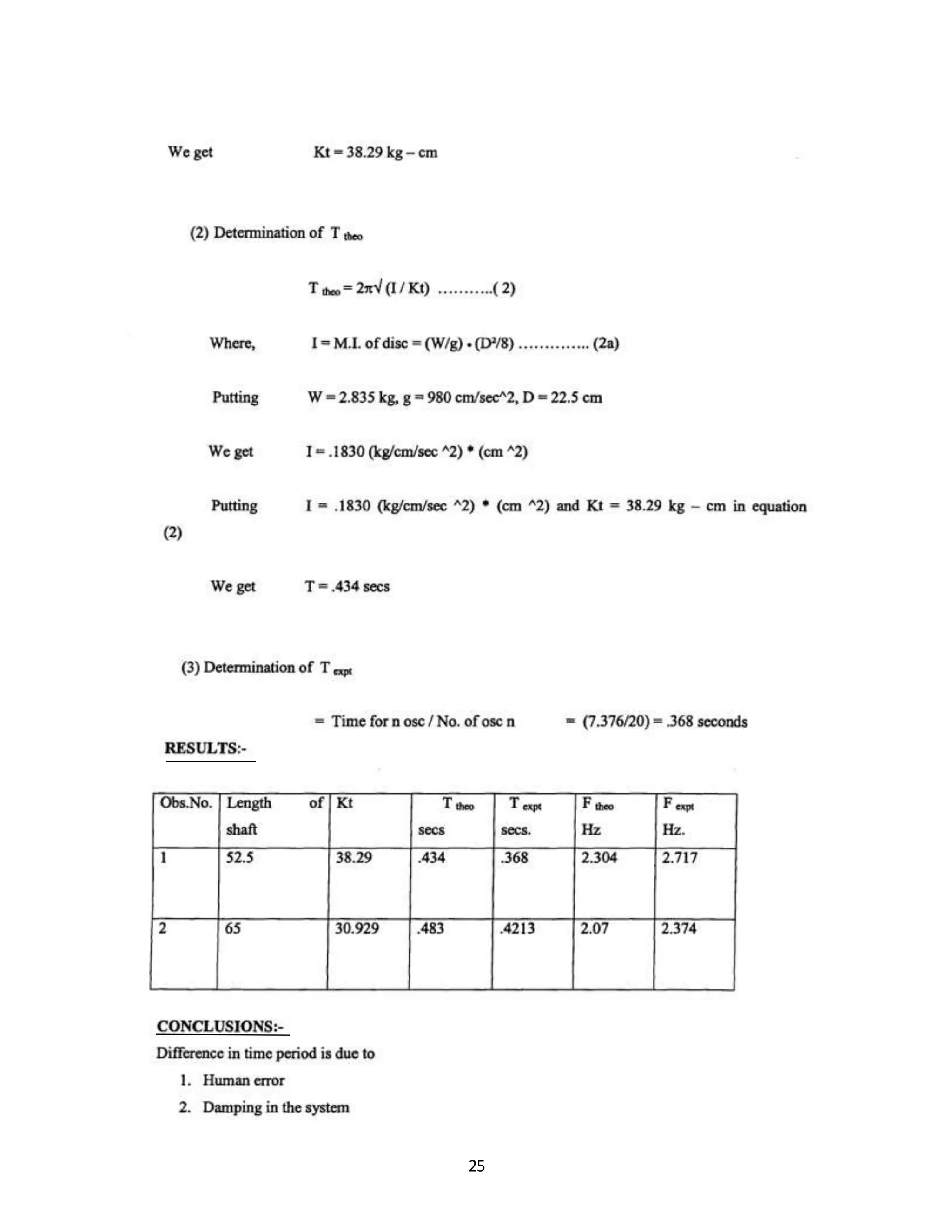
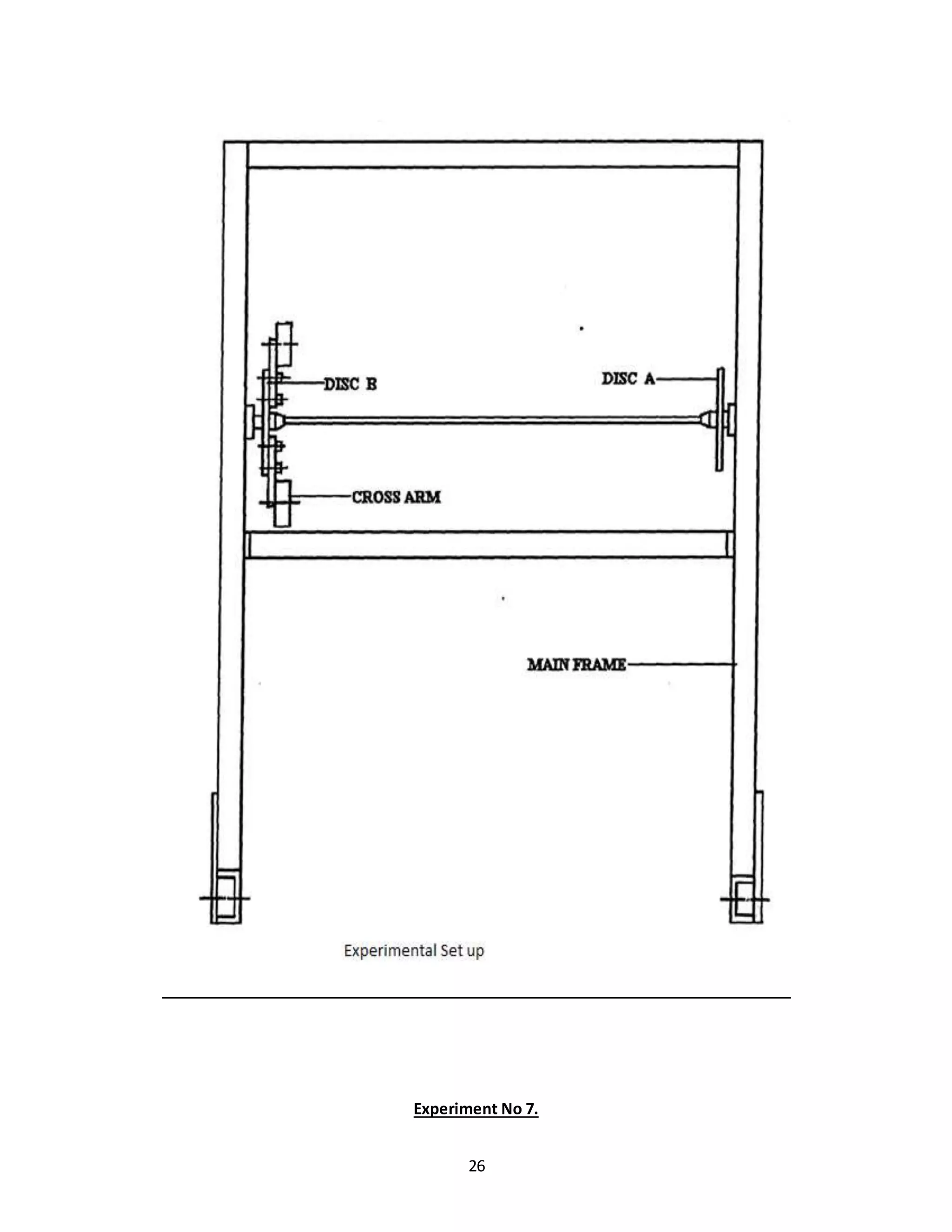
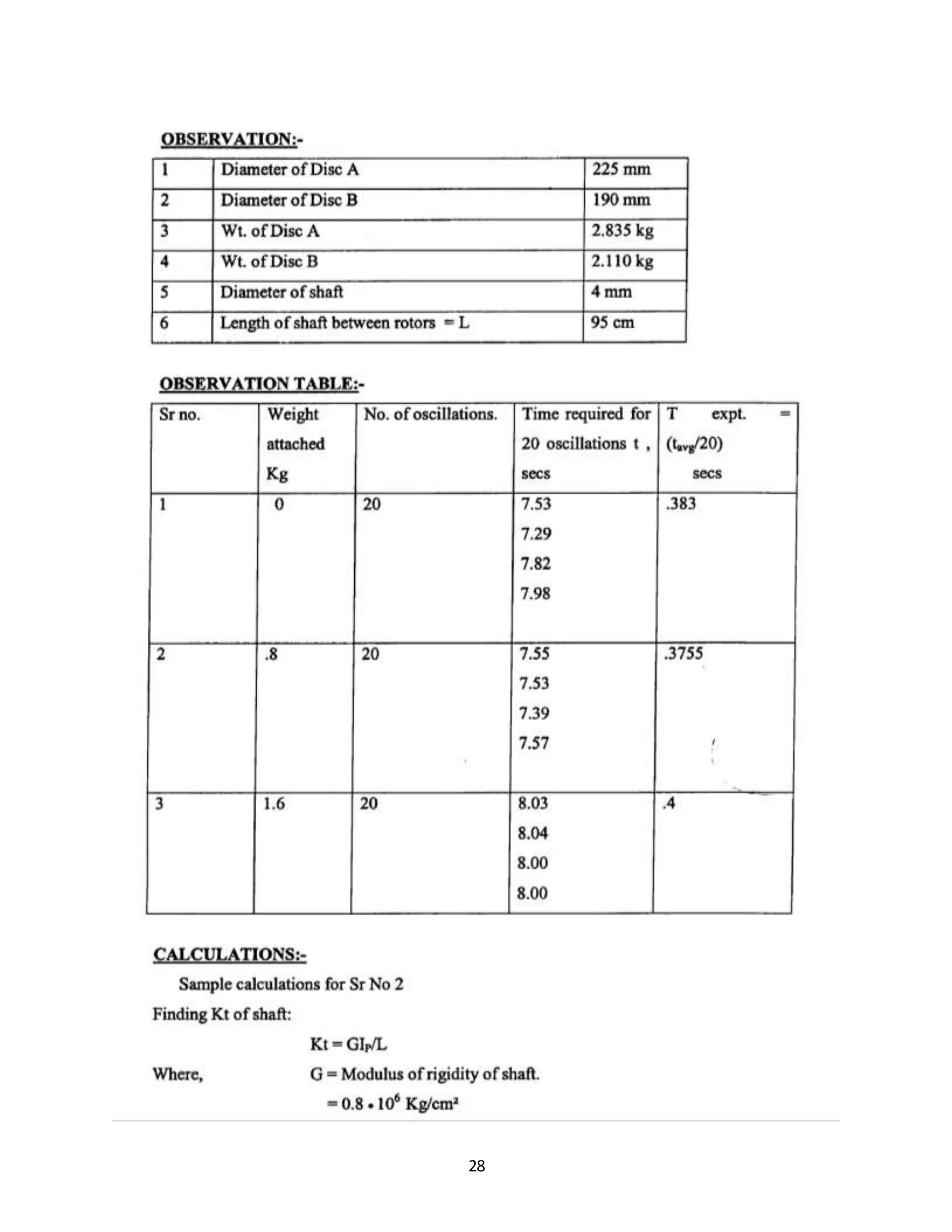
![27
Experiment No 7.
TORSIONAL VIBRATION OF DOUBLE ROTOR SYSTEM
AIM: To studytorsional vibrationof adouble rotorshaftsystem.Andtodetermine theoretical and
experimental value of natural frequency.
DISCRIPTION OF SET UP:
The arrangementisanshownin fig.Two discshavingdifferentmassmomentof inertiaare clampedone
at each endof shaft bymeansof colletandchucks.MassMomentof inertiaof anydisccan br changed
by attachingthe cross leverweights.BothDiscsare free tooscillate inball bearings.This provides
negligible dampingduringexperiment.
PROCEDURE:
1] Fixedtwodiscsto the shaftsandfit the shaftinbearing..
3] Apply angularmotiontotwo discsinopposite direction byhandandreleased.
4] Measure the oscillationof the periodfornno. of oscillations.
5] Fit the cross arm to one of the discssayB and againnote downtime.
6]Repeatthe peocedure withdifferentmassesandnote downtime.](https://image.slidesharecdn.com/allexperiments-1-150330000251-conversion-gate01/75/All-experiments-1-27-2048.jpg)
![30
CONCLUSION:
Differentinpractical andtheoretical timeperioddue to
1] Human error
2] Dampingfactor
3] Slip](https://image.slidesharecdn.com/allexperiments-1-150330000251-conversion-gate01/75/All-experiments-1-30-2048.jpg)
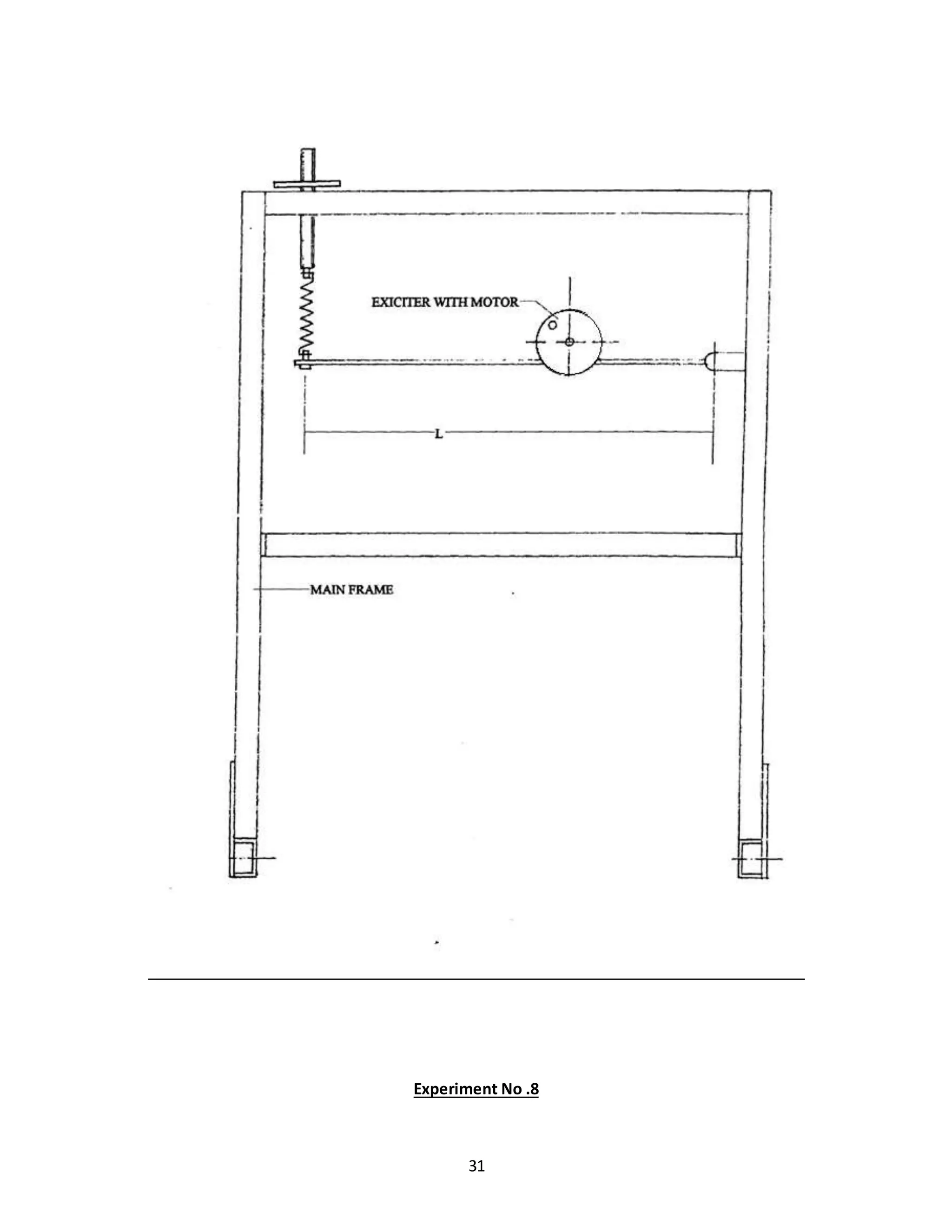
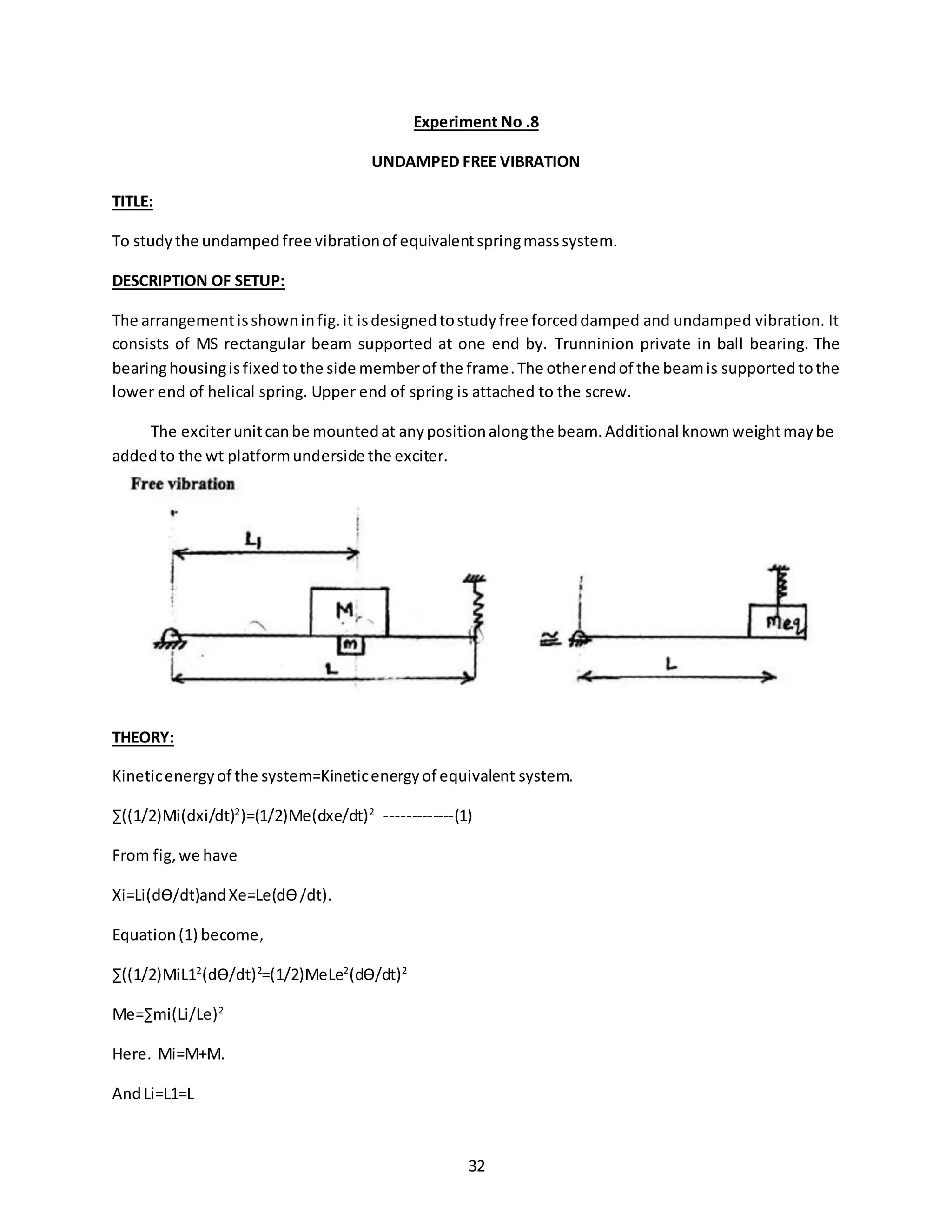
![33
Meq=(M+M)*(L1/L)2
Andnowdoingsimilaranalysisasinabove analysis.
PROCEDURE:
1] Supportone endof the beamin the slatof trunionand clampit by a meansof screw.
2] Attach the otherendof beamto the lowerendof spring.
3] Adjustthe screwto whichthe springisattached. Such that the beamis horizontallyinthe above
position.
4] Weightthe exciterassembly alongwithdisc&bearingendweightplatform.
5] Clampthe assemblyatany convenientposition.
6] Measure the distance L1 of the assemblyfromprivate.
7] Measure the time forany IOsecandfindthe periodictime andnature frequency.
8] Repeatthe experimentbyvaryingL1and by pottingdifferentweightonthe platform.](https://image.slidesharecdn.com/allexperiments-1-150330000251-conversion-gate01/75/All-experiments-1-33-2048.jpg)
![39
Experiment No 10.
DAMPED TORSIONAL VIBRATION
AIM:
To study damped torsional oscillation and determine damping coefficient.
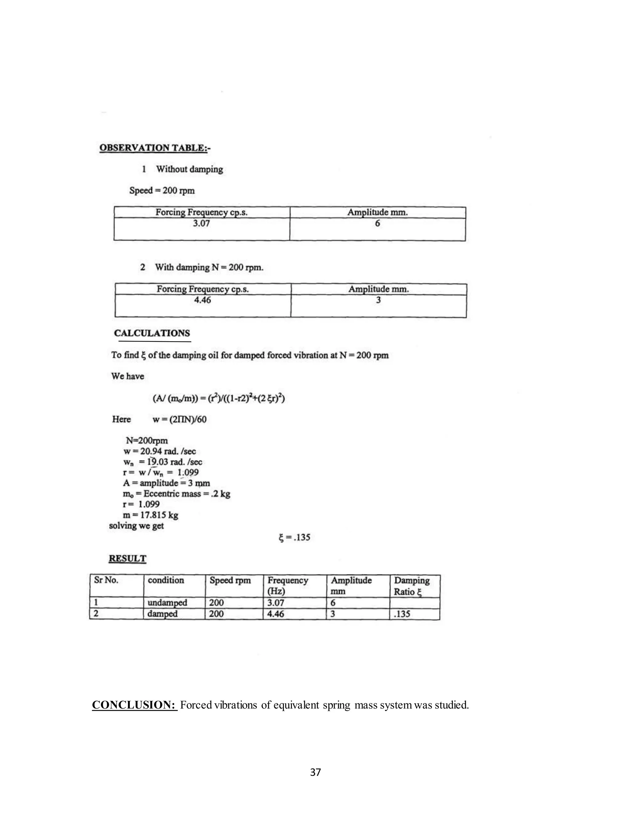
DESCRIPTION OF SET UP:
The fig showsgeneral arrangementforexperiment.Itconsistsof longelasticshaft gripped at upper end
by chuckin bracket.The bracket isclampedtoupperbeamof mainframe.A heavyflywheel Clamped to
lowerendof shaft suspended frombracket,thisdrumisimmersedinoil whichprovides damping. Rotor
can be takenupand downfor varyingdepthof immersionof dampingdrum,depthof immersion can be
read on scale.
PROCEDURE:
1] With no container allow flywheel to oscillate and measure time for 10 Oscillations.
2] Put thin mineral oil in drum and note depth of immersion.
3] Allow flywheel to vibrate.
4] Put sketching pen in bucket.
5] Allow pen to descend see that pen always makes contact with paper and record oscillations.
6] Measure time for some oscillations by means of stop watch.
7] Determine amplitudes of any positions.
OBSERVATION TABLE:
Sr.
no.
Damping medium Xn Xn+1
1 Air 1.4 1.3
2 Water 1.15 0.6
3 Oil 1 0.6](https://image.slidesharecdn.com/allexperiments-1-150330000251-conversion-gate01/75/All-experiments-1-39-2048.jpg)
![42
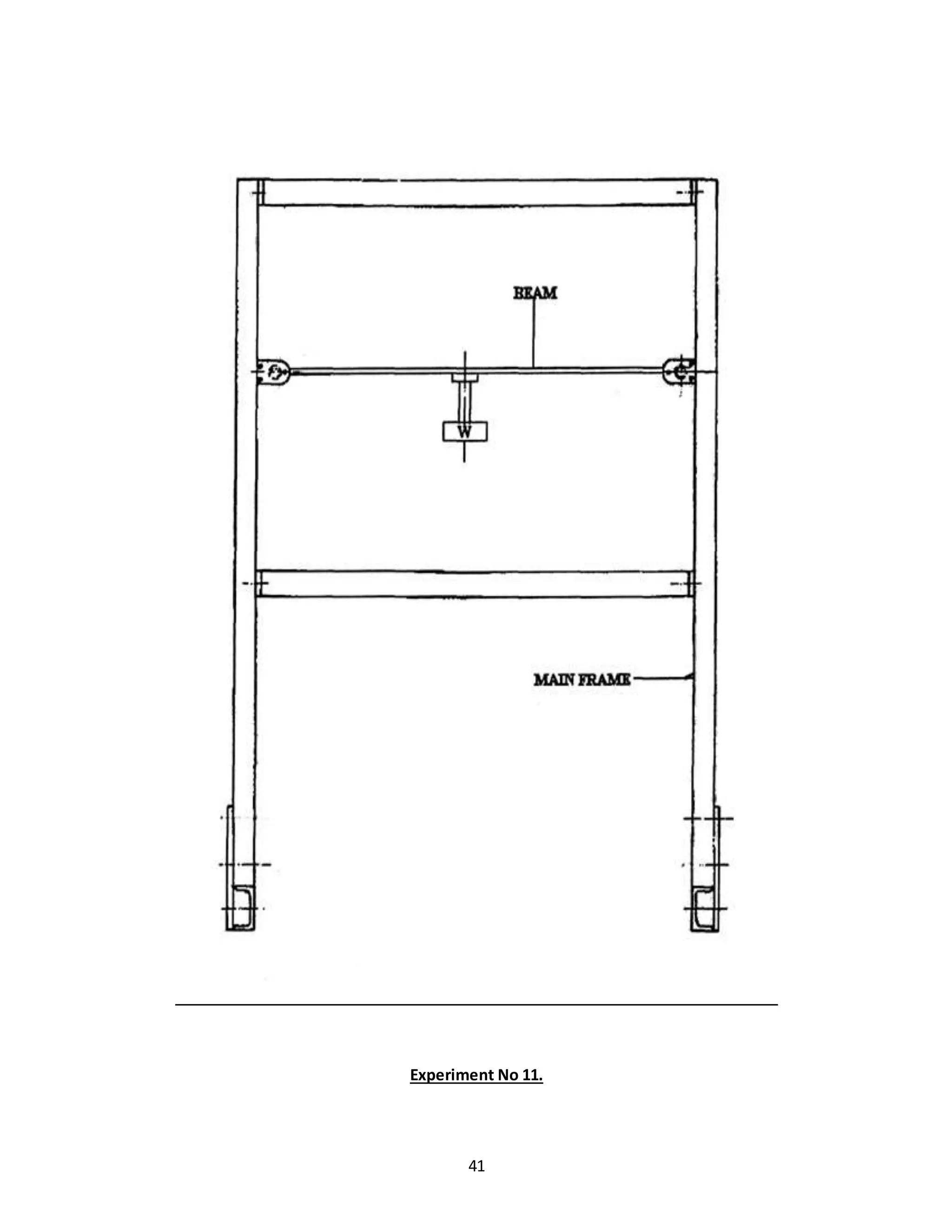
Experiment No 11.
DUNKERLEY’S RULE
AIM:
To verifyDunkerley’s
1
𝐅^𝟐
+=
1
𝐅𝐋^𝟐
+
1
𝐅𝐁^𝟐
Where F = Natural frequencyof beamwithcentral loadw.
FL=Natural frequencyof givenbeamwithcentral loadtobe calculatedas:
Fb =√
48𝐸𝐼𝑔
4𝑊𝜋^2𝐿^3
L = Lengthof beam
W = Central Load.
Fb =Natural Frequency
DISCRIPTION OF SET UP:
The fig showngeneral arrangementforcarryingexperimenta rectangular beam supported on a trunion
at each end ,each trunion is pivoted on ball burning carried in housing & is fixed to vertical frame
member. The beam carries at its center a weight platform
.
PROCEDURE:
1] Arrange the setup as shown with some weight W clamped to weight platform.
2] Pull the plat form and release it to set the system into natural vibration.
3] Find the periodic time T and frequency of vibration by measuring time for some oscillation.
4] Repeat expt by additional mass on weight platform.](https://image.slidesharecdn.com/allexperiments-1-150330000251-conversion-gate01/75/All-experiments-1-42-2048.jpg)

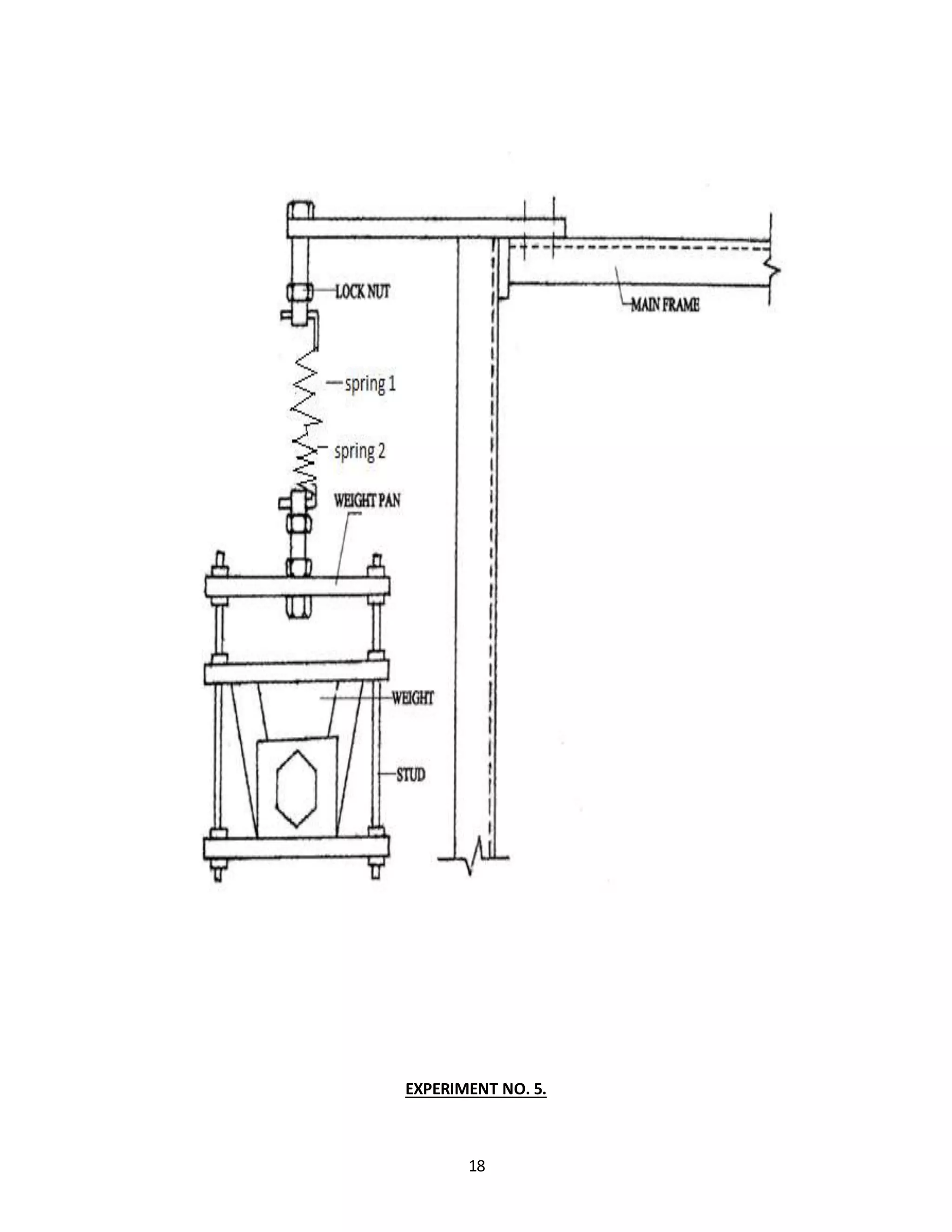
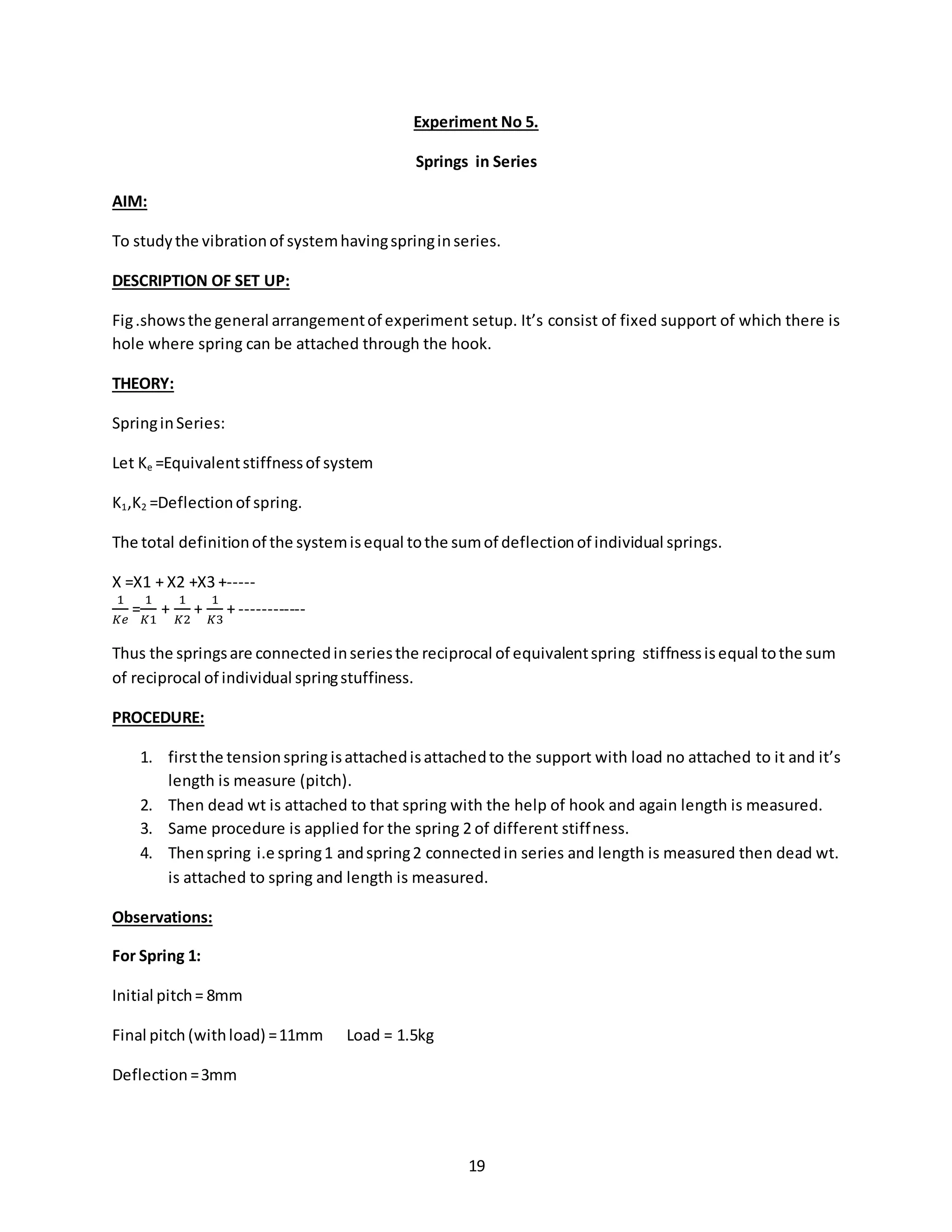
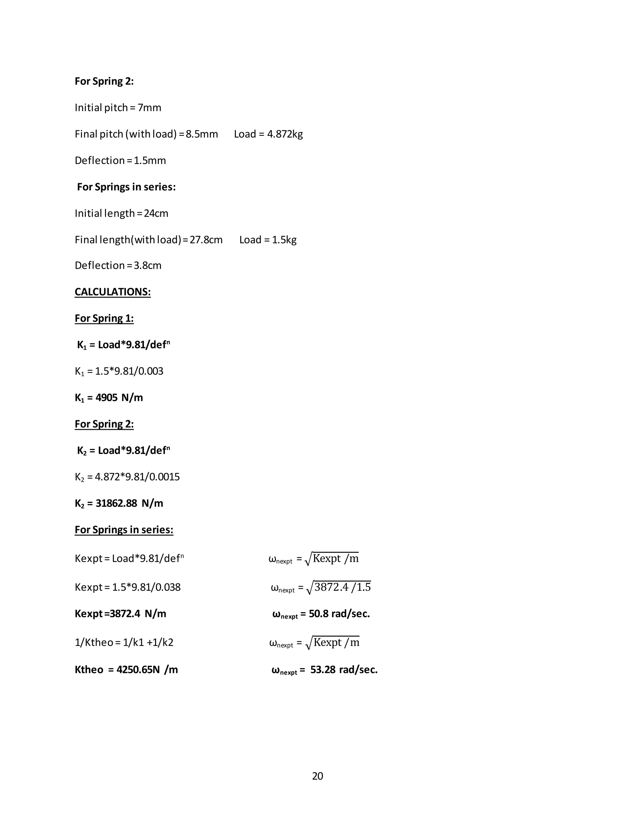
1. The document describes 5 experiments related to mechanical oscillations and vibrations. Experiment 1 verifies the relation between the period of a simple pendulum and its length. Experiment 2 determines the radius of gyration of a compound pendulum. 2. Experiment 3 uses a bifilar suspension to determine the radius of gyration of a bar. Experiment 4 studies longitudinal vibrations of a helical spring and determines the frequency theoretically and experimentally. 3. Experiment 5 examines vibrations of a system with springs in series. Each experiment involves setting up the apparatus, collecting observations in tables, performing calculations, and drawing conclusions by comparing experimental and theoretical results.


![Physics-2_Presentation_Mid[1].pptx](https://cdn.slidesharecdn.com/ss_thumbnails/physics-2presentationmid1-230729173429-559a3a64-thumbnail.jpg?width=640&height=640&fit=bounds)


