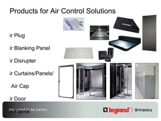
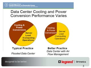
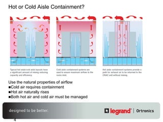
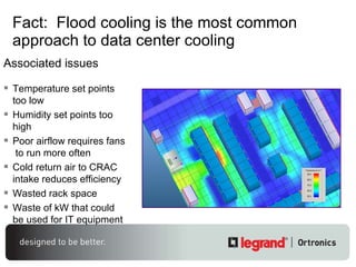
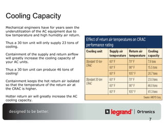
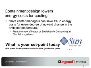
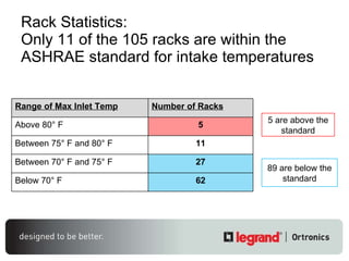
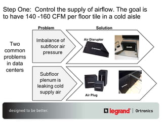
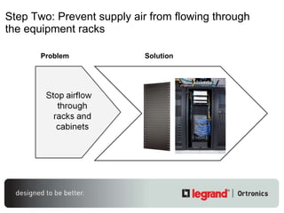
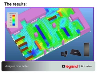
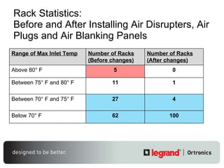
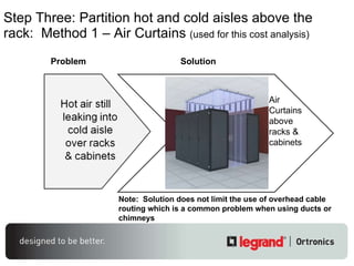
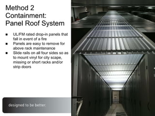
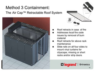
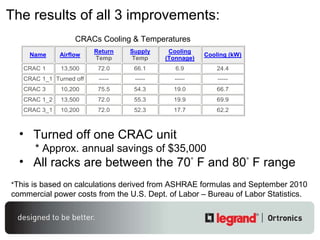
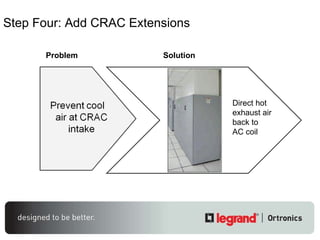
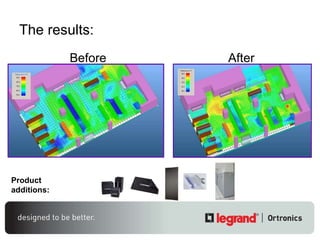
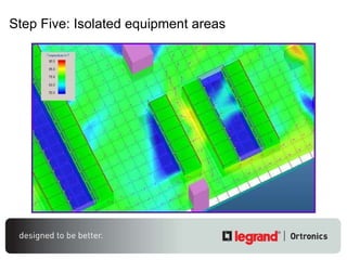
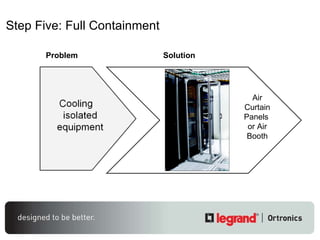
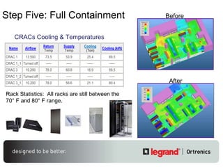
Air Control Solutions
Products for Air Control Solutions Air Plug Air Blanking Panel Air Disrupter Air Curtains/Panels/   Air Cap Air Door Air Frame Air Booth Air Extension Air Grille
Flooded Data Center Data Center with Air Flow Management
Hot or Cold Aisle Containment? Use the natural properties of airflow Cold air requires containment Hot air naturally rises Both hot air and cold air must be managed
Fact:  Flood cooling is the most common approach to data center cooling  Associated issues Temperature set points too low Humidity set points too high Poor airflow requires fans  to run more often Cold return air to CRAC intake reduces efficiency Wasted rack space Waste of kW that could be used for IT equipment
ASHRAE/Equipment manufacturers’ standards have changed Operational Temperatures in Data Centers have  RADICALLY CHANGED.  There is ABSOLUTELY NO reason to operate at 68°F to 70°F.  Operate data centers at temperatures at 75°F to 80°F to SAVE energy without impacting performance. You are NOT at risk; industry recognized ASHRAE environmental specifications provide a quotable source. Psychrometric Chart ASHRAE 2004 – Recommended ASHRAE – Allowable ASHRAE 2008 Recommended OLD NEW
Cooling Capacity Mechanical engineers have for years seen the underutilization of the AC equipment due to low temperature and high humidity air return.  Thus a 30 ton unit will only supply 23 tons of cooling.  Containment of the supply and return airflow will greatly increase the cooling capacity of your AC units.  Thus a 30 ton unit can produce 46 tons of cooling! Containment keeps the hot return air isolated so that the temperature of the return air at the CRAC is higher. Hotter return air will greatly increase the AC cooling capacity.
Benefits Increase in temperature set point (energy $) Decrease in humidity set point (energy $) Increased cooling capacity (capital $) Increase of facility longevity (capital $) Increase of use of rack space (capital $) Fast ROI (inside of one year or less) Delay of capital expense
Containment   design lowers energy costs for cooling “ Data center managers can save 4% in energy costs for every degree of upward change in the ambient temperature.” Mark Monroe, Director of Sustainable Computing at Sun Microsystems What is your set-point today? (the lower the temperature set-point the greater the potential savings)
Reasons the cooling system may not be efficient Cold air pumped into raised floor not rising through perforated tiles Mixing of hot and cold air through spaces in racks and cabinets CRAC units pulling in cold air instead of hot Too many obstacles for good airflow 9000 Sq. Ft. Data Center
 
Rack Statistics:  Only 11 of the 105 racks are within the ASHRAE standard for intake temperatures 5 are above the standard 89 are below the standard Range of Max Inlet Temp Number of Racks Above 80° F 5 Between 75° F and 80° F 11 Between 70° F and 75° F 27 Below 70° F 62
Step One:  Control the supply of airflow.  The goal is to have 140 -160 CFM per floor tile in a cold aisle Two common problems in data centers Problem Solution Air Disrupter Air Plug
Step Two:  P revent supply air from flowing through the equipment racks Problem Solution
The results:
Rack Statistics:  Before and After Installing Air Disrupters, Air Plugs and Air Blanking Panels Range of Max Inlet Temp Number of Racks (Before changes) Number of Racks (After changes) Above 80° F 5 0 Between 75° F and 80° F 11 1 Between 70° F and 75° F 27 4 Below 70° F 62 100
Step Three:  Partition hot and cold aisles above the rack:  Method 1 – Air Curtains  (used for this cost analysis) Problem Solution Air Curtains above racks & cabinets Note:  Solution does not limit the use of overhead cable routing which is a common problem when using ducts or chimneys
Method 2  Containment: Panel Roof System UL/FM rated drop-in panels that fall in event of a fire Panels are easy to remove for above rack maintenance Slide rails on all four sides so as to mount vinyl for city scape, missing or short racks and/or strip doors
Method 3 Containment:  The   Air Cap™ Retractable Roof System Roof retracts in case  of fire Addresses local fire code issues by removal of burn material Roof retracts for above rack maintenance Slide rails on all four sides to mount vinyl curtains for cityscape, missing or short racks and/or strip doors
The results of all 3 improvements: * This is based on calculations derived from ASHRAE formulas and September 2010 commercial power costs from the U.S. Dept. of Labor – Bureau of Labor Statistics. Turned off one CRAC unit * Approx. annual savings of $35,000 All racks are between the 70 °  F and 80 °  F range CRACs Cooling & Temperatures
Step Four:  Add CRAC Extensions Problem Solution Direct hot exhaust air back to AC coil
The results: After Before Product additions:
Step Five: Isolated equipment areas
Step Five:  Full Containment Problem Solution Air Curtain Panels  or Air Booth
Step Five:  Full Containment   After Before Rack Statistics:  All racks are still between the 70° F and 80° F range. CRACs Cooling & Temperatures
 

Afcom air control solution presentation

  • 1.
  • 2.
    Products for AirControl Solutions Air Plug Air Blanking Panel Air Disrupter Air Curtains/Panels/ Air Cap Air Door Air Frame Air Booth Air Extension Air Grille
  • 3.
    Flooded Data CenterData Center with Air Flow Management
  • 4.
    Hot or ColdAisle Containment? Use the natural properties of airflow Cold air requires containment Hot air naturally rises Both hot air and cold air must be managed
  • 5.
    Fact: Floodcooling is the most common approach to data center cooling Associated issues Temperature set points too low Humidity set points too high Poor airflow requires fans to run more often Cold return air to CRAC intake reduces efficiency Wasted rack space Waste of kW that could be used for IT equipment
  • 6.
    ASHRAE/Equipment manufacturers’ standardshave changed Operational Temperatures in Data Centers have RADICALLY CHANGED. There is ABSOLUTELY NO reason to operate at 68°F to 70°F. Operate data centers at temperatures at 75°F to 80°F to SAVE energy without impacting performance. You are NOT at risk; industry recognized ASHRAE environmental specifications provide a quotable source. Psychrometric Chart ASHRAE 2004 – Recommended ASHRAE – Allowable ASHRAE 2008 Recommended OLD NEW
  • 7.
    Cooling Capacity Mechanicalengineers have for years seen the underutilization of the AC equipment due to low temperature and high humidity air return. Thus a 30 ton unit will only supply 23 tons of cooling. Containment of the supply and return airflow will greatly increase the cooling capacity of your AC units. Thus a 30 ton unit can produce 46 tons of cooling! Containment keeps the hot return air isolated so that the temperature of the return air at the CRAC is higher. Hotter return air will greatly increase the AC cooling capacity.
  • 8.
    Benefits Increase intemperature set point (energy $) Decrease in humidity set point (energy $) Increased cooling capacity (capital $) Increase of facility longevity (capital $) Increase of use of rack space (capital $) Fast ROI (inside of one year or less) Delay of capital expense
  • 9.
    Containment design lowers energy costs for cooling “ Data center managers can save 4% in energy costs for every degree of upward change in the ambient temperature.” Mark Monroe, Director of Sustainable Computing at Sun Microsystems What is your set-point today? (the lower the temperature set-point the greater the potential savings)
  • 10.
    Reasons the coolingsystem may not be efficient Cold air pumped into raised floor not rising through perforated tiles Mixing of hot and cold air through spaces in racks and cabinets CRAC units pulling in cold air instead of hot Too many obstacles for good airflow 9000 Sq. Ft. Data Center
  • 11.
  • 12.
    Rack Statistics: Only 11 of the 105 racks are within the ASHRAE standard for intake temperatures 5 are above the standard 89 are below the standard Range of Max Inlet Temp Number of Racks Above 80° F 5 Between 75° F and 80° F 11 Between 70° F and 75° F 27 Below 70° F 62
  • 13.
    Step One: Control the supply of airflow. The goal is to have 140 -160 CFM per floor tile in a cold aisle Two common problems in data centers Problem Solution Air Disrupter Air Plug
  • 14.
    Step Two: P revent supply air from flowing through the equipment racks Problem Solution
  • 15.
  • 16.
    Rack Statistics: Before and After Installing Air Disrupters, Air Plugs and Air Blanking Panels Range of Max Inlet Temp Number of Racks (Before changes) Number of Racks (After changes) Above 80° F 5 0 Between 75° F and 80° F 11 1 Between 70° F and 75° F 27 4 Below 70° F 62 100
  • 17.
    Step Three: Partition hot and cold aisles above the rack: Method 1 – Air Curtains (used for this cost analysis) Problem Solution Air Curtains above racks & cabinets Note: Solution does not limit the use of overhead cable routing which is a common problem when using ducts or chimneys
  • 18.
    Method 2 Containment: Panel Roof System UL/FM rated drop-in panels that fall in event of a fire Panels are easy to remove for above rack maintenance Slide rails on all four sides so as to mount vinyl for city scape, missing or short racks and/or strip doors
  • 19.
    Method 3 Containment: The Air Cap™ Retractable Roof System Roof retracts in case of fire Addresses local fire code issues by removal of burn material Roof retracts for above rack maintenance Slide rails on all four sides to mount vinyl curtains for cityscape, missing or short racks and/or strip doors
  • 20.
    The results ofall 3 improvements: * This is based on calculations derived from ASHRAE formulas and September 2010 commercial power costs from the U.S. Dept. of Labor – Bureau of Labor Statistics. Turned off one CRAC unit * Approx. annual savings of $35,000 All racks are between the 70 ° F and 80 ° F range CRACs Cooling & Temperatures
  • 21.
    Step Four: Add CRAC Extensions Problem Solution Direct hot exhaust air back to AC coil
  • 22.
    The results: AfterBefore Product additions:
  • 23.
    Step Five: Isolatedequipment areas
  • 24.
    Step Five: Full Containment Problem Solution Air Curtain Panels or Air Booth
  • 25.
    Step Five: Full Containment After Before Rack Statistics: All racks are still between the 70° F and 80° F range. CRACs Cooling & Temperatures
  • 26.

Editor's Notes

  • #2 Today we’ll walk you through basic solutions for Air Control & Containment in the Data Center as well as how various steps implemented can directly affect your cooling / energy bill.
  • #3 This presentation will suggest best practices that can be followed using the Mighty Mo Air Control products to execute passive thermal management. It will help to prepare you to discuss different ways that your customers can improve the cooling efficiency within their datacenter with products that will not add heat, nor require additional power - both of which can add to the overall operating cost. You will see the relative value of each best practice as it relates to both energy savings and increased cooling capacity. Each step builds on the previous best practice. Results after sub-floor airflow products are installed. Results after sub-floor airflow products and rack blanking panels are installed. Results after sub-floor airflow, blanking panels and above-floor containment products are installed. Results after sub-floor airflow, blanking panels, above-floor containment and CRAC extensions are installed. Results after adding containment to isolated areas.
  • #5 Mighty Mo ® cable management systems are fully equipped to handle the density of today ’s high performance networks while allowing for easy moves, adds, and changes, including: Support for up to 1340 network ports Capacity for a minimum of 48 Category 6a patch cords on a single side of the equipment Adjustable mounting rails from 12.5 ” to 30” to handle and route copper or fiber cables without impeding airflow
  • #6 Flood Cooling is the most common approach to data center cooling. This process fills the entire room with cold air to meet the needs of all active equipment intake levels. Because flood cooling relies on the ability of cold air to evenly distribute in a space with many barriers, common problems occur: ~ There are lower than necessary temperature set points ~ There are higher than required humidity set points ~ Poor airflow requires fans to run more often Additionally, because airflow is usually poor, cold air is often at the CRAC intake, reducing its efficiency. There is often wasted rack space as equipment is “spread out” among the racks to help minimize the heat build up. © 2008 Sub Zero Engineering. All rights reserved. Company Confidential.
  • #7 Layer Zero infrastructure solutions manage airflow and heat across the entire network using a passive cooling design. Enhancing the barrier between the hot and cold aisle with airflow baffles creates a proper airflow pattern and helps eliminate hot air recirculation within the cabinets. This improves thermal management; eliminating hot spots and allowing better equipment ventilation - ultimately protecting equipment from overheating. Cooling is more efficient and power consumption for cooling is reduced. Honeycomb side rails allow for better equipment ventilation and air movement. Airflow baffles create a passive barrier to isolate cold aisle and hot aisle air more effectively Raceways and wire mesh cable trays promote air circulation.
  • #8 Hot Server Rooms & Data Centers Heat exhaust from servers and switches, plus higher density demands, raise the ambient room temperature and create hot spots . If left unchecked, this additional heat can lead to equipment failure . An additional challenge is that electrical cooling solutions can add to the heat load, decreasing their effectiveness.
  • #10 Layer Zero adds to the bottom line As mentioned in the previous slide, in a study performed by Legrand | Ortronics, the Mighty Mo airflow baffle solution reduced the exhaust temperature by 20°. The intake air only needed to be cooled to 65°F. Since the system without any hot aisle cold aisle separation needed intake air cooled to 50°F to generate the same lower exhaust temperature, the ambient temperature threshold was able to be raised by 15°F. This created a 60% reduction in energy costs for cooling switches. 65°F - 50°F = 15°F. 15°F X 4% = 60% *The thermal studies referenced as the basis for this equation were compiled using a series of three network cabinets and a series of three Mighty Mo 10 racks within the center of a row of a data center; not a full data center. These analyses were conducted as separate tests. By installing the Mighty Mo airflow baffles system, the exhaust air temperature from both the series of cabinets and racks was reduced by 20°, decreasing from a temperature of 105° to 85°. As a result of the ability to decrease the exhaust temperature, the intake air only needed to be cooled to 65° to maintain an acceptable ambient room temperature. The comparative systems, cabinets using neither side panels, nor divider panels, cabinets using only divider panels and a standard EIA rack configuration, needed an intake temperature of 50° to achieve the same cooler exhaust temperature. The difference in intake temperatures or set points is 15°. At the 2007 AFCOM Data Center World Conference, Mark Monroe, the Director of Sustainable Computing at Sun Microsystems, stated that " Data center managers can save 4% in energy costs for every degree of upward change in the set point. ” Using the 4% savings, multiplied by the 15° change = 60. This is the 60% energy savings for cooling switches. Please note that a data center manager would see variability depending on the size of the data center, the way racks and cabinets were loaded, etc. Also, please note that the statement references cooling costs only - as opposed to overall energy or electricity costs - and by specifying switches, it aligns with the data that we have gathered.
  • #11 There are many reasons that a cooling system may not be efficient: ~ Cold air pumped into the raised floor may not be rising through the perforated tiles ~ There may be a mixing of hot and cold air through spaces in racks and cabinets resulting in hot air at the intake of equipment ~ CRAC units might be pulling cool air instead of warm or hot air, reducing their capacity and efficiency ~ There are too many obstacles for good airflow, creating very inconsistent temperatures throughout the data center The example used in this presentation uses Computational Fluid Dynamics (CFD) analysis to illustrate the energy savings impact after installing a series of airflow management products starting with subfloor "best practices" and ending with full containment. The baseline model is a 9,000 square foot data center. The baseline model is a typical data center with kW or heat loads ranging from 0.5 kW network racks to 6 kW server racks. It also features racks that are both parallel and perpendicular to the five operating CRAC units. Other special situations include a non-raised floor area, racks up against a wall or column and CRAC units that are not symmetrical. There are some aisles correctly laid out for a hot and cold aisle arrangement and some rows are isolated.
  • #12 We are looking at a cross section of the area highlighted in the original data center shown in the upper left corner.   This area is setup in a cold aisle / hot aisle configuration but there are many problems, including a hot spot. The air from the subfloor via the perforated tiles is not sufficient to cool the racks and cabinets. Hot air is short cycling* into the cold aisle.   Cold air is being wasted as it leaks into the hot aisle. This also results in cold air being pulled into the CRAC units, making them much less efficient.   *Note: In this case, short cycling refers to hot air taking the shortest path to cold air.
  • #13 Going back to our sample data center, five racks are above the ASHRAE standard and in danger of having equipment problems or failure. Only 11 of the 105 total are within the guidelines. 89 are below the standard, meaning energy is being wasted through excessive cooling.  
  • #14 Step 1 in airflow management is to control the supply airflow. Our model has the cold air supplied from under the raised floor. The goal is to have 140-160 CFM (cubic feet per minute) of cold air supply coming from each perforated tile in a cold aisle.   Most data centers do not achieve the desired air flow for two reasons: There is an imbalance of subfloor air pressure The subfloor plenum is leaking cold supply air into the ambient room   Strategically placing MM Air Disrupters in the midst of the supplied air flow will create turbulence, decreasing the air velocity and allowing the air to travel up through the perforated floor tile, into the cold aisle.   Eliminating all raised floor holes can be accomplished by using the MM Air Plugs. This will prevent cold air from leaking from the subfloor.
  • #15 Step 2 is to prevent cold supply air from flowing through the equipment racks without passing through a thermal load (equipment to be cooled). This is accomplished by using MM Air Blanking Panels.   Filling gaps with these panels helps prevent hot exhaust air from re-circulating back into the equipment intake.   Because they come as one, 27 RU sheet scored at every 1 RU, they can be sized by breaking off the rack units needed to cover the opening.
  • #16 The illustration shown simulates the use of Air Disrupters, Air Plugs and Air Blanking Panels. Notice the vast improvement to the cold air supply side of the IT equipment (solid blue indicates cold supply air in the cold aisle). Most of the hot spots have been eliminated: The Air Disrupters have slowed the flow of air, ensuring cold air is able to flow up through the perforated tiles in front of racks and cabinets. The Air Plugs have eliminated airflow leaks from cable openings and other gaps in the raised floor. The Air Blanking Panels have reduced the recycling of hot air into the cold aisle. The intake temperature of the IT equipment benefits from the greater concentration of cooler air.
  • #17 There has been significant improvement in cooling; there are no longer any racks overheating. Only 1 rack is within the desired temperature range. All other racks are below the temperature range. 104 racks are being excessively cooled; 100 by over 10 ° F - a considerable waste of energy. The single rack is preventing us from raising the operating temperature set point.
  • #18 Step 3 is to partition hot and cold aisles above the rack. Without partitioning, hot air is still short cycling into the cold aisle above the racks and cabinets.   The two cold aisles are contained with Air Curtain Vinyl Panels and the aisle ends with Air Curtain Vinyl Strip Doors. This separation enabled the facility to run with one less 22 Ton CRAC unit!   Note: This solution does not limit the use of overhead cable routing which is a common problem when using ducts or chimneys.  
  • #21 Cooling capacity increased from 5 CRAC units , supporting 63.5 tons of cooling to 4 CRAC units , supporting 63.5 tons of cooling. This has allowed 1 CRAC unit to be turned off!   That is an efficiency increase of 12.7 tons of cooling or 3.17 tons per unit.   The approximate annual operational savings gained by turning off 1 22 Ton CRAC unit is $35,000.*     *This is based on calculations derived from ASHRAE formulas and September 2010 commercial power costs from the U.S. Dept. of Labor – Bureau of Labor Statistics.  
  • #22 Step 4 after adding Air Curtains is to direct the hot exhaust air back to the AC coil through the drop ceiling void.   Adding a CRAC Unit Extension up to the drop ceiling ensures that only hot air is returned to the CRAC intake.     Because the CRAC units are now more efficient, in addition to one CRAC unit turned off in step 3, we are now able to increase the set-point temperature 10 degrees! This increase will save over 30% of cooling energy. In our model this translates to an additional $42,000 in energy savings.
  • #23 The “After” model shows the installed CRAC Extensions (the shadow above the CRAC units). You can also see the CRAC unit that was turned off in step 3, marked by a red “X”.   Notice that the “After” model shows overall warmer temperatures because the set point has been raised by 10° F.   Temperatures are in the range of 70° F to 80° F, as they should be. Remember we don't want to overcool the equipment and waste energy and ASHRAE recommends the operating temperature to be between 75° F and 80° F.  
  • #24 Steps 1 through 4 have resulted in major improvements in the cooling efficiency of the data center. The final step addresses lost cooling efficiency in the isolated equipment areas. These areas were not laid out in a hot aisle / cold aisle configuration.
  • #25 When cooling equipment that is in a single row or is facing the exhaust of other equipment, a cold aisle can be created by using curtains to form the three walls needed to contain the cold air in front of the equipment.    For one or two isolated racks or cabinets, an Air Booth can be used to contain the cold air, as shown in the picture.
  • #26 Our model shows that with full containment, which includes isolated equipment (those not in hot and cold aisles) two CRAC units can be shut off. This series of CFD models illustrate the progressive value of airflow management. It shows that true passive thermal management can result in significant energy savings and therefore, cost savings.