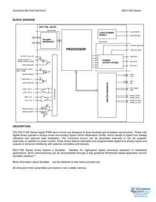
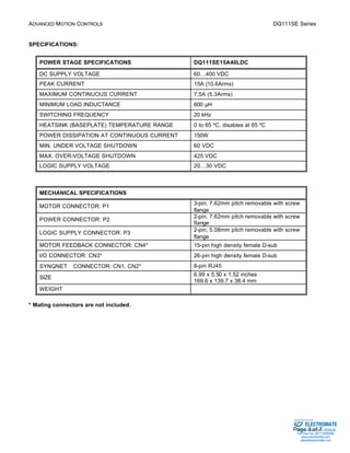
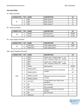
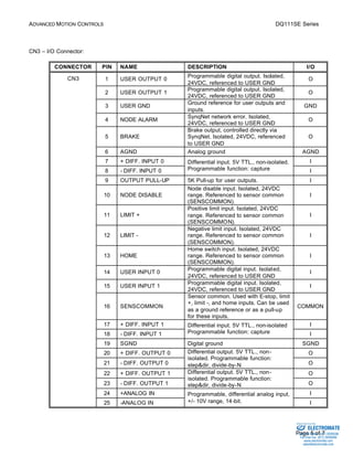
DQ111SE Series 
DIGIFLEX® DIGITAL SERVO DRIVES 
MODEL: DQ111SE15A40LDC 
WITH INTERFACE 
FEATURES: 
·  Fully digital, state-of-the-art design 
·  Space Vector Modulation and vector control technology 
·  20kHz Digital current loop with programmable gain settings 
·  Sine/cosine encoder (1Vpp) based sinusoidal commutation 
·  Supports Heidenhain Endat® and Stegmann Hiperface® interface 
(absolute position readout) 
·  Up to 11-bit sine/cosine interpolation (x2048) provides high 
resolution position feedback (contact factory for higher resolution) 
·  Surface-mount technology 
·  Small size, low cost, ease of use 
·  SynqNetä motion control network interface 
·  Windows95/98/2000/ME/NT© based setup software for setup via 
SynqNet™ interface 
·  Operates in torque mode with programmable gain settings and 
current limiting 
·  2 programmable isolated digital inputs 
·  2 programmable isolated digital outputs 
·  Dedicated Brake and Node Alarm outputs 
·  14-bit reference input or programmable analog input 
·  2 high-speed differential inputs (high-speed capture, encoder 
input) 
·  2 high-speed differential outputs (step&dir, divide-by-N) 
·  Dedicated, isolated node disable, positive and negative limits, and 
home inputs 
·  Separate logic supply 
·  Four quadrant regenerative operation 
·  Bi-color LED status indicator 
·  Extensive built-in protection against: 
§ over-voltage (programmable) 
§ under-voltage (programmable) 
·  short-circuit: phase-phase, phase-ground 
§ over-current 
§ over-temperature 
Sold & Serviced By: 
ELECTROMATE 
Toll Free Phone (877) SERVO98 
Toll Free Fax (877) SERV099 
www.electromate.com 
sales@electromate.com
ADVANCED MOTION CONTROLS DQ111SE Series 
AUX POWER 
AUX GROUND 
POWER GROUND 
GND 
RS485_DATA-RS485_ 
Sold & Serviced By: 
Page 2 of 7 
BLOCK DIAGRAM: 
SynqNet 
INTERFACE 
20K 
5K 
5K 
20K 
MOTOR FEEDBACK 
PROCESSOR 
DQ111SE...40LDC 
ISOLATION 
I/O INTERFACE 
OUTPUT PULL-UP 
USER INPUT 0...1 
USER GROUND 
+ 
- 
20K 
20K 
+DIFF. OUT 0...1 
-DIFF. OUT 0...1 
+DIFF. IN 0...1 
-DIFF. IN 0...1 
+ANALOG INPUT 
-ANALOG INPUT 
5K 
500 
USER OUTPUT 0..1, 
BRAKE, NODE ALARM 
USER GROUND 
COS + 
COS - 
SIN + 
SIN - 
REF MARK 
RS485_DATA+ 
RS485_CLOCK+ 
CLOCK-SENSCOMMON 
NODE DISABLE, LIMIT+, 
LIMIT-, HOME 
ISOLATION 
MOTOR A 
MOTOR B 
MOTOR C 
LOGIC POWER 
SUPPLY 
HIGH VOLTAGE 
POWER 
OUTPUT STAGE 
DESCRIPTION: 
The DQ111SE Series digital PWM servo drives are designed to drive brushed and brushless servomotors. These fully 
digital drives operate in torque mode and employ Space Vector Modulation (SVM), which results in higher bus voltage 
utilization and reduced heat dissipation. The command source can be generated internally or can be supplied 
externally. In addition to motor control, these drives feature dedicated and programmable digital and analog inputs and 
outputs to enhance interfacing with external controllers and devices. 
DQ111SE Series drives feature a SynqNetä interface for high-speed digital command operation in networked 
applications. Drive commissioning can be accomplished through a fully graphical Windows© based application via the 
SynqNet interface™. 
More information about SynqNetä can be obtained at http://www.synqnet.org. 
All drive and motor parameters are stored in non-volatile memory. 
ELECTROMATE 
Toll Free Phone (877) SERVO98 
Toll Free Fax (877) SERV099 
www.electromate.com 
sales@electromate.com
ADVANCED MOTION CONTROLS DQ111SE Series 
Sold & Serviced By: 
Page 3 of 7 
SPECIFICATIONS: 
POWER STAGE SPECIFICATIONS DQ111SE15A40LDC 
DC SUPPLY VOLTAGE 60…400 VDC 
PEAK CURRENT 15A (10.6Arms) 
MAXIMUM CONTINUOUS CURRENT 7.5A (5.3Arms) 
MINIMUM LOAD INDUCTANCE 600 μH 
SWITCHING FREQUENCY 20 kHz 
HEATSINK (BASEPLATE) TEMPERATURE RANGE 0 to 65 ºC, disables at 65 ºC 
POWER DISSIPATION AT CONTINUOUS CURRENT 150W 
MIN. UNDER VOLTAGE SHUTDOWN 60 VDC 
MAX. OVER-VOLTAGE SHUTDOWN 425 VDC 
LOGIC SUPPLY VOLTAGE 20…30 VDC 
MECHANICAL SPECIFICATIONS 
MOTOR CONNECTOR: P1 3-pin; 7.62mm pitch removable with screw 
flange 
POWER CONNECTOR: P2 2-pin; 7.62mm pitch removable with screw 
flange 
LOGIC SUPPLY CONNECTOR: P3 2-pin; 5.08mm pitch removable with screw 
flange 
MOTOR FEEDBACK CONNECTOR: CN4* 15-pin high density female D-sub 
I/O CONNECTOR: CN3* 26-pin high density female D-sub 
SYNQNETä CONNECTOR: CN1, CN2* 8-pin RJ45 
SIZE 6.99 x 5.50 x 1.52 inches 
169.6 x 139.7 x 38.4 mm 
WEIGHT 
* Mating connectors are not included. 
ELECTROMATE 
Toll Free Phone (877) SERVO98 
Toll Free Fax (877) SERV099 
www.electromate.com 
sales@electromate.com
ADVANCED MOTION CONTROLS DQ111SE Series 
Sold & Serviced By: 
Page 4 of 7 
PIN FUNCTIONS: 
P1 - Motor Connector: 
CONNECTOR PIN NAME DESCRIPTION I/O 
1 MA Motor phase A O 
P1 2 MB Motor phase B O 
3 MC Motor phase C O 
P2 – Power Connector: 
CONNECTOR PIN NAME DESCRIPTION I/O 
1 PGND Power ground PGND 
P2 
2 HV IN DC motor supply HV IN 
P3 – Logic Supply Connector: 
CONNECTOR PIN NAME DESCRIPTION I/O 
1 RTN AUX Logic supply ground GND 
P3 
2 PWR AUX Logic supply power I 
CN4 - Motor Feedback Connector: 
CONNECTOR PIN NAME DESCRIPTION I/O 
1 COS + Cosine input. Voltage range: 2 – 3.4 
I 
2 COS - 
VDC. Frequency range: DC – 200kHz I 
3 SIN + Cosine input. Voltage range: 2 – 3.4 
I 
4 SIN - 
VDC. Frequency range: DC – 200kHz I 
5 SGND Signal ground SGND 
6 RS485_DATA- I/O 
7 RS485_DATA+ 
Differential data line for sine/cosine 
encoder. 
I/O 
8 RS485_CLOCK+ clock line for sine/cosine 
O 
encoder 
9 RS485_CLOCK-Differential 
O 
10 +5V OUT +5V @ 250mA max. Short-circuit 
protected. 
O 
11 NC Not connected 
12 NC Not connected 
13 REF MARK Reference mark from sine/cosine 
encoder 
I 
14 NC Not connected 
CN4 
15 Reserved 
ELECTROMATE 
Toll Free Phone (877) SERVO98 
Toll Free Fax (877) SERV099 
www.electromate.com 
sales@electromate.com
ADVANCED MOTION CONTROLS DQ111SE Series 
Sold & Serviced By: 
Page 5 of 7 
CN3 – I/O Connector: 
CONNECTOR PIN NAME DESCRIPTION I/O 
1 USER OUTPUT 0 Programmable digital output. Isolated, 
24VDC, referenced to USER GND 
O 
2 USER OUTPUT 1 Programmable digital output. Isolated, 
24VDC, referenced to USER GND 
O 
3 USER GND Ground reference for user outputs and 
inputs. 
GND 
4 NODE ALARM SynqNet network error. Isolated, 
24VDC, referenced to USER GND 
O 
5 BRAKE 
Brake output, controlled directly via 
SynqNet. Isolated, 24VDC, referenced 
to USER GND 
O 
6 AGND Analog ground AGND 
7 + DIFF. INPUT 0 Differential input. 5V TTL., non-isolated. 
I 
8 - DIFF. INPUT 0 
Programmable function: capture I 
9 OUTPUT PULL-UP 5K Pull-up for user outputs. I 
10 NODE DISABLE 
Node disable input. Isolated, 24VDC 
range. Referenced to sensor common 
(SENSCOMMON). 
I 
11 LIMIT + 
Positive limit input. Isolated, 24VDC 
range. Referenced to sensor common 
(SENSCOMMON). 
I 
12 LIMIT - 
Negative limit input. Isolated, 24VDC 
range. Referenced to sensor common 
(SENSCOMMON). 
I 
13 HOME 
Home switch input. Isolated, 24VDC 
range. Referenced to sensor common 
(SENSCOMMON). 
I 
14 USER INPUT 0 Programmable digital input. Isolated, 
24VDC, referenced to USER GND 
I 
15 USER INPUT 1 Programmable digital input. Isolated, 
24VDC, referenced to USER GND 
I 
16 SENSCOMMON 
Sensor common. Used with E-stop, limit 
+, limit -, and home inputs. Can be used 
as a ground reference or as a pull-up 
for these inputs. 
COMMON 
17 + DIFF. INPUT 1 Differential input. 5V TTL., non-isolated 
I 
18 - DIFF. INPUT 1 
Programmable function: capture I 
19 SGND Digital ground SGND 
20 + DIFF. OUTPUT 0 Differential output. 5V TTL., non-isolated. 
O 
Programmable function: 
21 - DIFF. OUTPUT 0 
step&dir, divide-by-N O 
Differential output. 5V TTL., non-isolated. 
22 + DIFF. OUTPUT 1 O 
Programmable function: 
23 - DIFF. OUTPUT 1 
step&dir, divide-by-N O 
24 +ANALOG IN I 
CN3 
25 -ANALOG IN 
Programmable, differential analog input, 
+/- 10V range, 14-bit. I 
ELECTROMATE 
Toll Free Phone (877) SERVO98 
Toll Free Fax (877) SERV099 
www.electromate.com 
sales@electromate.com
ADVANCED MOTION CONTROLS DQ111SE Series 
26 AGND Analog ground. AGND 
Sold & Serviced By: 
Page 6 of 7 
CN1 – SYNQNETä INTERFACE: 
CONNECTOR PIN NAME DESCRIPTION I/O 
1 RD+ I 
100BaseT receiver 
2 RD- 
I 
3 TD+ O 
100BaseT transmitter 
6 TD- 
O 
CN1 
4, 5, 
7, 8 
N/C Not connected 
CN2 – SYNQNETä INTERFACE: 
CONNECTOR PIN NAME DESCRIPTION I/O 
1 TD+ O 
100BaseT transmitter 
2 TD- 
O 
3 RD+ I 
100BaseT receiver 
6 RD- 
I 
CN2 
4, 5, 
7, 8 
N/C Not connected 
ORDERING INFORMATION: 
Standard model: DQ111SE15A40LDCX 
X indicates the current revision letter. 
ELECTROMATE 
Toll Free Phone (877) SERVO98 
Toll Free Fax (877) SERV099 
www.electromate.com 
sales@electromate.com
ADVANCED MOTION CONTROLS DQ111SE Series 
Sold & Serviced By: 
Page 7 of 7 
MOUNTING DIMENSIONS: 
ELECTROMATE 
Toll Free Phone (877) SERVO98 
Toll Free Fax (877) SERV099 
www.electromate.com 
sales@electromate.com

Advanced motion controls dq111se15a40ldc

  • 1.
    DQ111SE Series DIGIFLEX®DIGITAL SERVO DRIVES MODEL: DQ111SE15A40LDC WITH INTERFACE FEATURES: · Fully digital, state-of-the-art design · Space Vector Modulation and vector control technology · 20kHz Digital current loop with programmable gain settings · Sine/cosine encoder (1Vpp) based sinusoidal commutation · Supports Heidenhain Endat® and Stegmann Hiperface® interface (absolute position readout) · Up to 11-bit sine/cosine interpolation (x2048) provides high resolution position feedback (contact factory for higher resolution) · Surface-mount technology · Small size, low cost, ease of use · SynqNetä motion control network interface · Windows95/98/2000/ME/NT© based setup software for setup via SynqNet™ interface · Operates in torque mode with programmable gain settings and current limiting · 2 programmable isolated digital inputs · 2 programmable isolated digital outputs · Dedicated Brake and Node Alarm outputs · 14-bit reference input or programmable analog input · 2 high-speed differential inputs (high-speed capture, encoder input) · 2 high-speed differential outputs (step&dir, divide-by-N) · Dedicated, isolated node disable, positive and negative limits, and home inputs · Separate logic supply · Four quadrant regenerative operation · Bi-color LED status indicator · Extensive built-in protection against: § over-voltage (programmable) § under-voltage (programmable) · short-circuit: phase-phase, phase-ground § over-current § over-temperature Sold & Serviced By: ELECTROMATE Toll Free Phone (877) SERVO98 Toll Free Fax (877) SERV099 www.electromate.com sales@electromate.com
  • 2.
    ADVANCED MOTION CONTROLSDQ111SE Series AUX POWER AUX GROUND POWER GROUND GND RS485_DATA-RS485_ Sold & Serviced By: Page 2 of 7 BLOCK DIAGRAM: SynqNet INTERFACE 20K 5K 5K 20K MOTOR FEEDBACK PROCESSOR DQ111SE...40LDC ISOLATION I/O INTERFACE OUTPUT PULL-UP USER INPUT 0...1 USER GROUND + - 20K 20K +DIFF. OUT 0...1 -DIFF. OUT 0...1 +DIFF. IN 0...1 -DIFF. IN 0...1 +ANALOG INPUT -ANALOG INPUT 5K 500 USER OUTPUT 0..1, BRAKE, NODE ALARM USER GROUND COS + COS - SIN + SIN - REF MARK RS485_DATA+ RS485_CLOCK+ CLOCK-SENSCOMMON NODE DISABLE, LIMIT+, LIMIT-, HOME ISOLATION MOTOR A MOTOR B MOTOR C LOGIC POWER SUPPLY HIGH VOLTAGE POWER OUTPUT STAGE DESCRIPTION: The DQ111SE Series digital PWM servo drives are designed to drive brushed and brushless servomotors. These fully digital drives operate in torque mode and employ Space Vector Modulation (SVM), which results in higher bus voltage utilization and reduced heat dissipation. The command source can be generated internally or can be supplied externally. In addition to motor control, these drives feature dedicated and programmable digital and analog inputs and outputs to enhance interfacing with external controllers and devices. DQ111SE Series drives feature a SynqNetä interface for high-speed digital command operation in networked applications. Drive commissioning can be accomplished through a fully graphical Windows© based application via the SynqNet interface™. More information about SynqNetä can be obtained at http://www.synqnet.org. All drive and motor parameters are stored in non-volatile memory. ELECTROMATE Toll Free Phone (877) SERVO98 Toll Free Fax (877) SERV099 www.electromate.com sales@electromate.com
  • 3.
    ADVANCED MOTION CONTROLSDQ111SE Series Sold & Serviced By: Page 3 of 7 SPECIFICATIONS: POWER STAGE SPECIFICATIONS DQ111SE15A40LDC DC SUPPLY VOLTAGE 60…400 VDC PEAK CURRENT 15A (10.6Arms) MAXIMUM CONTINUOUS CURRENT 7.5A (5.3Arms) MINIMUM LOAD INDUCTANCE 600 μH SWITCHING FREQUENCY 20 kHz HEATSINK (BASEPLATE) TEMPERATURE RANGE 0 to 65 ºC, disables at 65 ºC POWER DISSIPATION AT CONTINUOUS CURRENT 150W MIN. UNDER VOLTAGE SHUTDOWN 60 VDC MAX. OVER-VOLTAGE SHUTDOWN 425 VDC LOGIC SUPPLY VOLTAGE 20…30 VDC MECHANICAL SPECIFICATIONS MOTOR CONNECTOR: P1 3-pin; 7.62mm pitch removable with screw flange POWER CONNECTOR: P2 2-pin; 7.62mm pitch removable with screw flange LOGIC SUPPLY CONNECTOR: P3 2-pin; 5.08mm pitch removable with screw flange MOTOR FEEDBACK CONNECTOR: CN4* 15-pin high density female D-sub I/O CONNECTOR: CN3* 26-pin high density female D-sub SYNQNETä CONNECTOR: CN1, CN2* 8-pin RJ45 SIZE 6.99 x 5.50 x 1.52 inches 169.6 x 139.7 x 38.4 mm WEIGHT * Mating connectors are not included. ELECTROMATE Toll Free Phone (877) SERVO98 Toll Free Fax (877) SERV099 www.electromate.com sales@electromate.com
  • 4.
    ADVANCED MOTION CONTROLSDQ111SE Series Sold & Serviced By: Page 4 of 7 PIN FUNCTIONS: P1 - Motor Connector: CONNECTOR PIN NAME DESCRIPTION I/O 1 MA Motor phase A O P1 2 MB Motor phase B O 3 MC Motor phase C O P2 – Power Connector: CONNECTOR PIN NAME DESCRIPTION I/O 1 PGND Power ground PGND P2 2 HV IN DC motor supply HV IN P3 – Logic Supply Connector: CONNECTOR PIN NAME DESCRIPTION I/O 1 RTN AUX Logic supply ground GND P3 2 PWR AUX Logic supply power I CN4 - Motor Feedback Connector: CONNECTOR PIN NAME DESCRIPTION I/O 1 COS + Cosine input. Voltage range: 2 – 3.4 I 2 COS - VDC. Frequency range: DC – 200kHz I 3 SIN + Cosine input. Voltage range: 2 – 3.4 I 4 SIN - VDC. Frequency range: DC – 200kHz I 5 SGND Signal ground SGND 6 RS485_DATA- I/O 7 RS485_DATA+ Differential data line for sine/cosine encoder. I/O 8 RS485_CLOCK+ clock line for sine/cosine O encoder 9 RS485_CLOCK-Differential O 10 +5V OUT +5V @ 250mA max. Short-circuit protected. O 11 NC Not connected 12 NC Not connected 13 REF MARK Reference mark from sine/cosine encoder I 14 NC Not connected CN4 15 Reserved ELECTROMATE Toll Free Phone (877) SERVO98 Toll Free Fax (877) SERV099 www.electromate.com sales@electromate.com
  • 5.
    ADVANCED MOTION CONTROLSDQ111SE Series Sold & Serviced By: Page 5 of 7 CN3 – I/O Connector: CONNECTOR PIN NAME DESCRIPTION I/O 1 USER OUTPUT 0 Programmable digital output. Isolated, 24VDC, referenced to USER GND O 2 USER OUTPUT 1 Programmable digital output. Isolated, 24VDC, referenced to USER GND O 3 USER GND Ground reference for user outputs and inputs. GND 4 NODE ALARM SynqNet network error. Isolated, 24VDC, referenced to USER GND O 5 BRAKE Brake output, controlled directly via SynqNet. Isolated, 24VDC, referenced to USER GND O 6 AGND Analog ground AGND 7 + DIFF. INPUT 0 Differential input. 5V TTL., non-isolated. I 8 - DIFF. INPUT 0 Programmable function: capture I 9 OUTPUT PULL-UP 5K Pull-up for user outputs. I 10 NODE DISABLE Node disable input. Isolated, 24VDC range. Referenced to sensor common (SENSCOMMON). I 11 LIMIT + Positive limit input. Isolated, 24VDC range. Referenced to sensor common (SENSCOMMON). I 12 LIMIT - Negative limit input. Isolated, 24VDC range. Referenced to sensor common (SENSCOMMON). I 13 HOME Home switch input. Isolated, 24VDC range. Referenced to sensor common (SENSCOMMON). I 14 USER INPUT 0 Programmable digital input. Isolated, 24VDC, referenced to USER GND I 15 USER INPUT 1 Programmable digital input. Isolated, 24VDC, referenced to USER GND I 16 SENSCOMMON Sensor common. Used with E-stop, limit +, limit -, and home inputs. Can be used as a ground reference or as a pull-up for these inputs. COMMON 17 + DIFF. INPUT 1 Differential input. 5V TTL., non-isolated I 18 - DIFF. INPUT 1 Programmable function: capture I 19 SGND Digital ground SGND 20 + DIFF. OUTPUT 0 Differential output. 5V TTL., non-isolated. O Programmable function: 21 - DIFF. OUTPUT 0 step&dir, divide-by-N O Differential output. 5V TTL., non-isolated. 22 + DIFF. OUTPUT 1 O Programmable function: 23 - DIFF. OUTPUT 1 step&dir, divide-by-N O 24 +ANALOG IN I CN3 25 -ANALOG IN Programmable, differential analog input, +/- 10V range, 14-bit. I ELECTROMATE Toll Free Phone (877) SERVO98 Toll Free Fax (877) SERV099 www.electromate.com sales@electromate.com
  • 6.
    ADVANCED MOTION CONTROLSDQ111SE Series 26 AGND Analog ground. AGND Sold & Serviced By: Page 6 of 7 CN1 – SYNQNETä INTERFACE: CONNECTOR PIN NAME DESCRIPTION I/O 1 RD+ I 100BaseT receiver 2 RD- I 3 TD+ O 100BaseT transmitter 6 TD- O CN1 4, 5, 7, 8 N/C Not connected CN2 – SYNQNETä INTERFACE: CONNECTOR PIN NAME DESCRIPTION I/O 1 TD+ O 100BaseT transmitter 2 TD- O 3 RD+ I 100BaseT receiver 6 RD- I CN2 4, 5, 7, 8 N/C Not connected ORDERING INFORMATION: Standard model: DQ111SE15A40LDCX X indicates the current revision letter. ELECTROMATE Toll Free Phone (877) SERVO98 Toll Free Fax (877) SERV099 www.electromate.com sales@electromate.com
  • 7.
    ADVANCED MOTION CONTROLSDQ111SE Series Sold & Serviced By: Page 7 of 7 MOUNTING DIMENSIONS: ELECTROMATE Toll Free Phone (877) SERVO98 Toll Free Fax (877) SERV099 www.electromate.com sales@electromate.com