Download to read offline
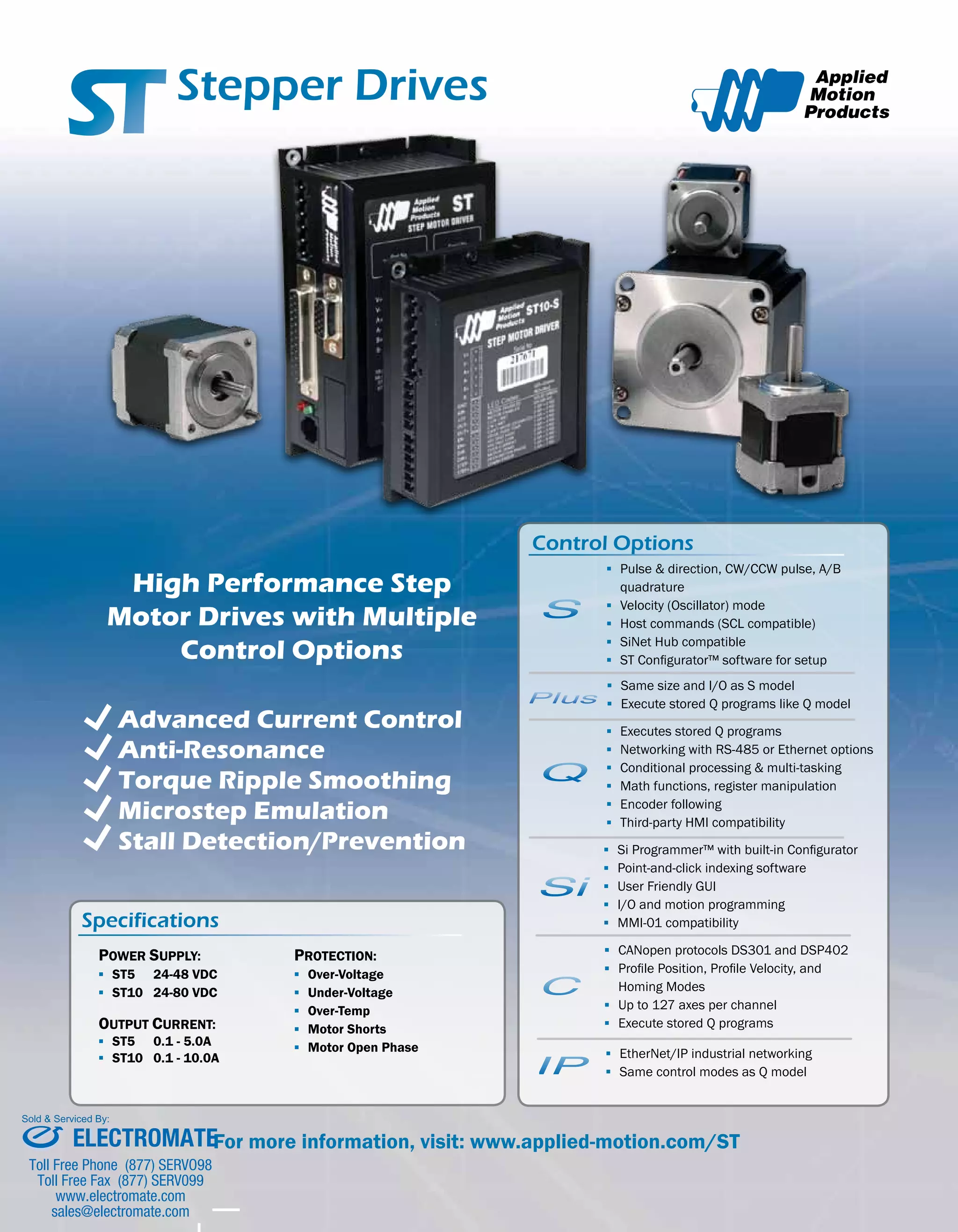
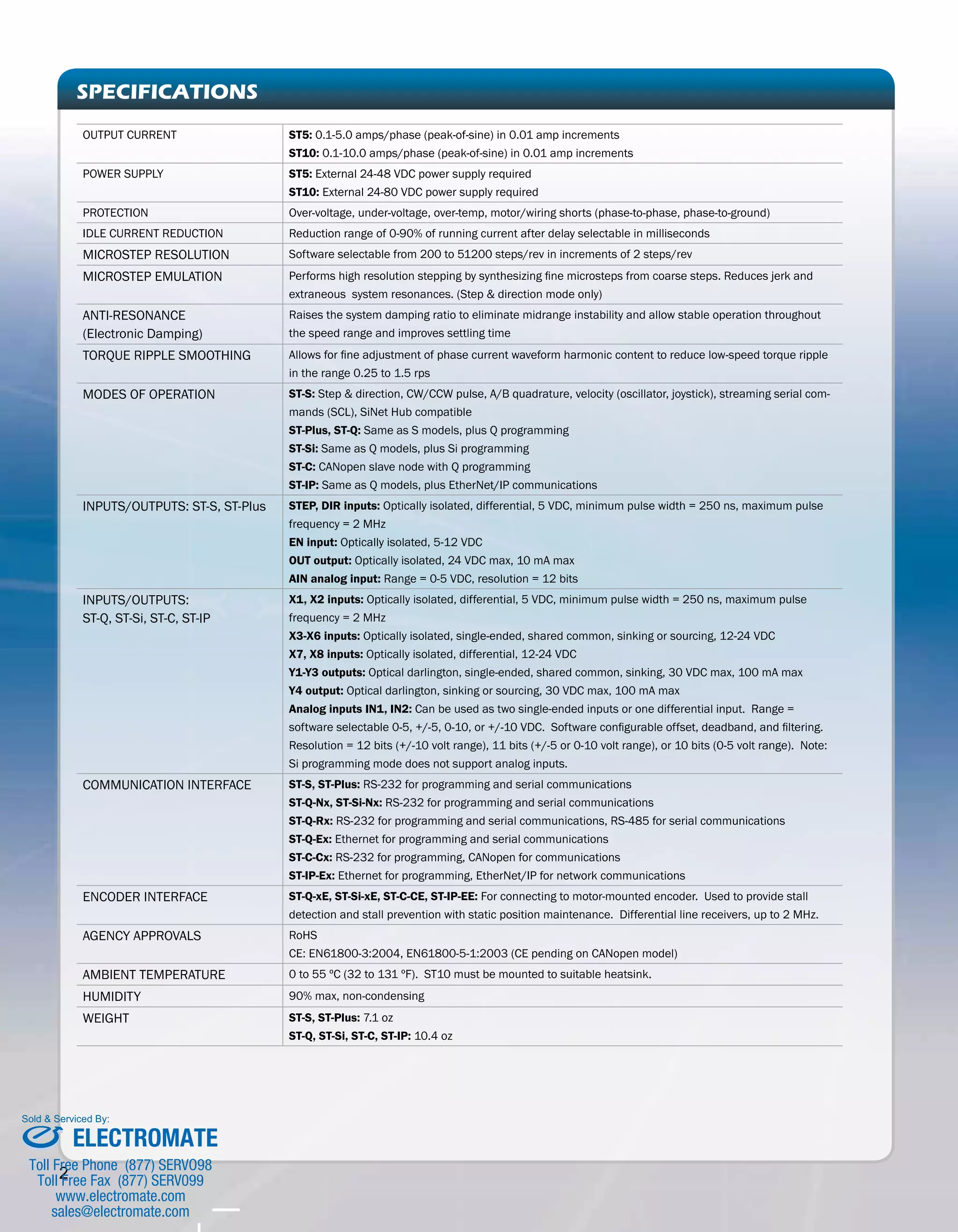
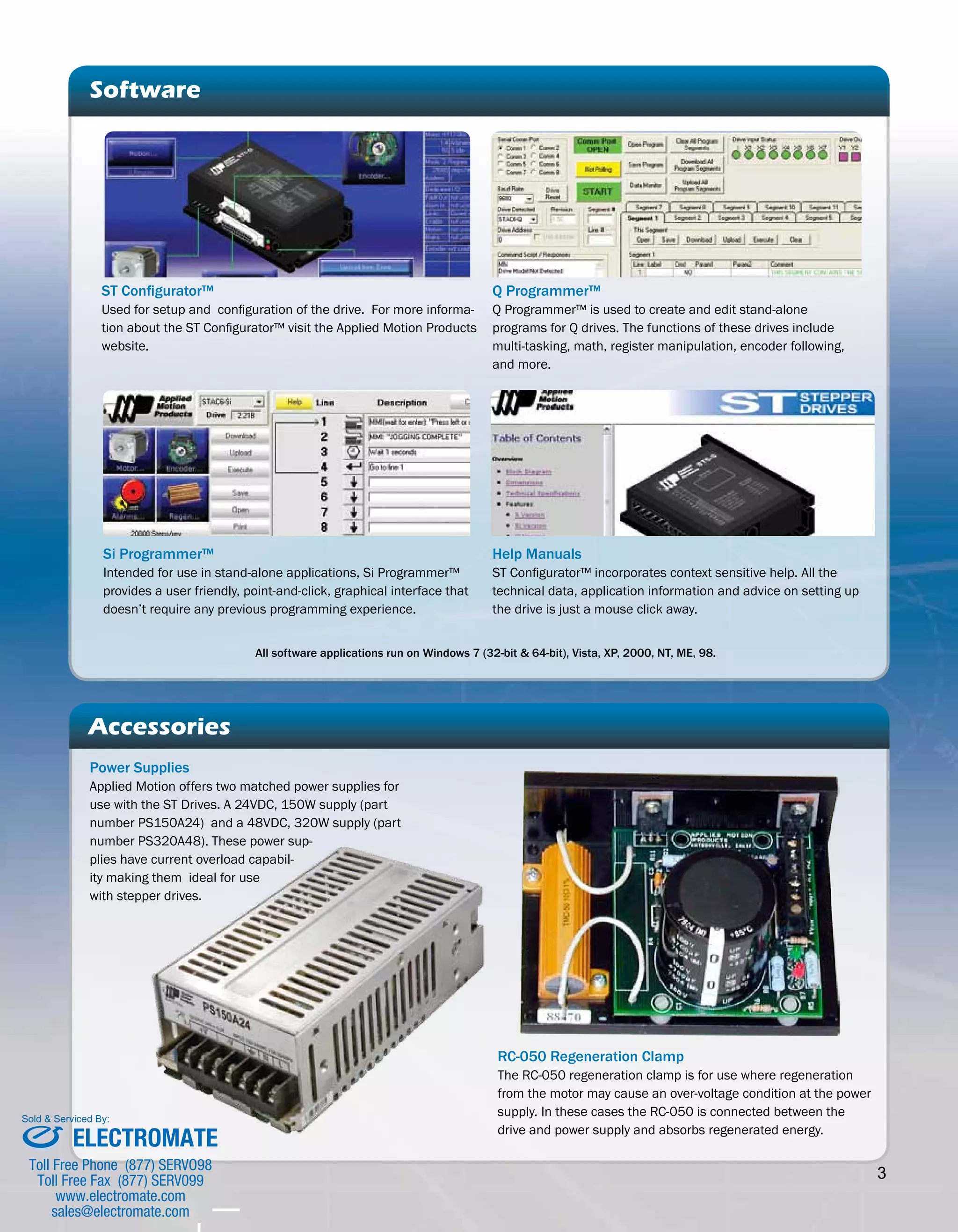

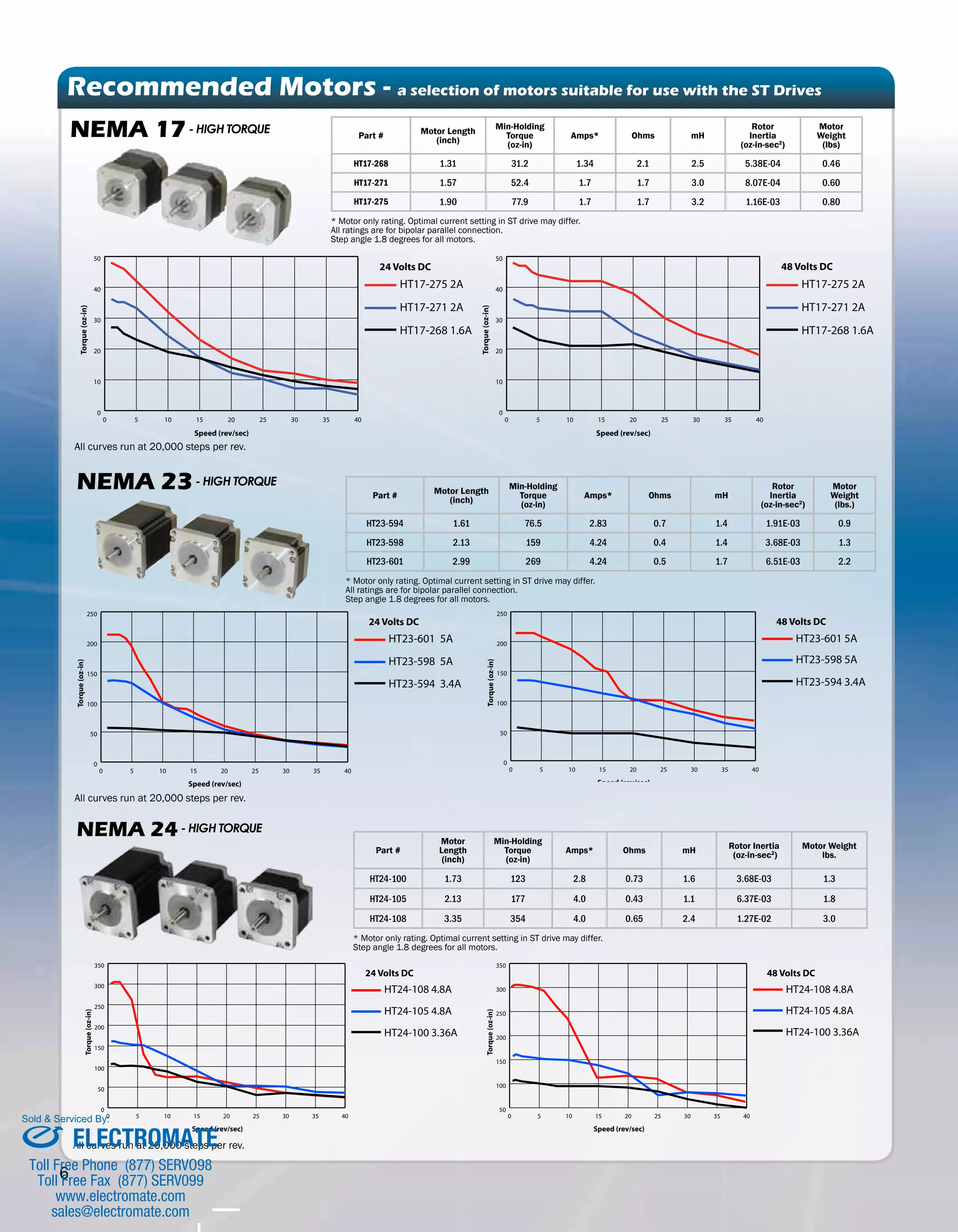

This document describes several step motor drive models with various control options. The ST drives can be controlled via pulse and direction, velocity mode, or host commands. Higher-level models also allow for programming, networking, and advanced motion control. The drives provide features like anti-resonance control, torque ripple smoothing, and stall prevention. Accessories include power supplies, regeneration clamps, and programming software.


![Coded Agents – with UiPath SDK + LangGraph [Virtual Hands-on Workshop]](https://cdn.slidesharecdn.com/ss_thumbnails/codedagentsdeck-251215155422-5497c599-thumbnail.jpg?width=640&height=640&fit=bounds)


