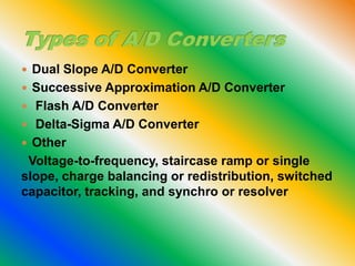
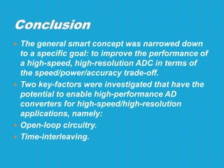
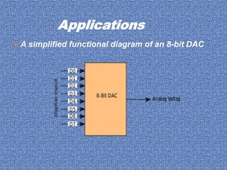
 An electronic integrated circuit which transforms
a signal from analog (continuous) to digital
(discrete) form.
 Analog signals are directly measurable
quantities.
 Digital signals only have two states. For digital
computer, we refer to binary states, 0 and 1.
 Microprocessors can only perform complex
processing on digitized signals.
 When signals are in digital form they are less
susceptible to the deleterious effects of additive
noise.
 ADC Provides a link between the analog world of
transducers and the digital world of signal
processing and data handling.
 ADC are used virtually everywhere where an
analog signal has to be processed, stored, or
transported in digital form.
 Some examples of ADC usage are digital volt
meters, cell phone, thermocouples, and digital
oscilloscope.
 Microcontrollers commonly use 8, 10, 12, or 16
bit ADCs, our micro controller uses an 8 or 10 bit
ADC.
 Dual Slope A/D Converter
 Successive Approximation A/D Converter
 Flash A/D Converter
 Delta-Sigma A/D Converter
 Other
Voltage-to-frequency, staircase ramp or single
slope, charge balancing or redistribution, switched
capacitor, tracking, and synchro or resolver
 The general smart concept was narrowed down
to a specific goal: to improve the performance of
a high-speed, high-resolution ADC in terms of
the speed/power/accuracy trade-off.
 Two key-factors were investigated that have the
potential to enable high-performance AD
converters for high-speed/high-resolution
applications, namely:
 Open-loop circuitry.
 Time-interleaving.
 In electronics, a digital-to-analog converter (DAC
or D-to-A) is a device that converts a digital
(usually binary) code to an analog signal
(current, voltage, or electric charge). An analog-
to-digital converter (ADC) performs the reverse
operation. Signals are easily stored and
transmitted in digital form, but a DAC is needed
for the signal to be recognized by human senses
or other non-digital systems.
 A common use of digital-to-analog converters is
generation of audio signals from digital
information in music players.
 A simplified functional diagram of an 8-bit DAC
 The pulse-width modulator, the simplest DAC type.
 A stable current or voltage is switched into a low-
pass analog filter with a duration determined by the
digital input code.
 This technique is often used for electric motor speed
control, but has many other applications as well.
 Resolution:
 Maximum sampling rate
 Monotonicity:
 THD+N :
 Dynamic range:
 The smart concept was applied to DA converters
with as aim to minimize the analog area as much
as possible, and to use digital processing
instead to solve the related accuracy problem.
Ad and da convertor

Ad and da convertor

  • 3.
     An electronicintegrated circuit which transforms a signal from analog (continuous) to digital (discrete) form.  Analog signals are directly measurable quantities.  Digital signals only have two states. For digital computer, we refer to binary states, 0 and 1.
  • 4.
     Microprocessors canonly perform complex processing on digitized signals.  When signals are in digital form they are less susceptible to the deleterious effects of additive noise.  ADC Provides a link between the analog world of transducers and the digital world of signal processing and data handling.
  • 5.
     ADC areused virtually everywhere where an analog signal has to be processed, stored, or transported in digital form.  Some examples of ADC usage are digital volt meters, cell phone, thermocouples, and digital oscilloscope.  Microcontrollers commonly use 8, 10, 12, or 16 bit ADCs, our micro controller uses an 8 or 10 bit ADC.
  • 6.
     Dual SlopeA/D Converter  Successive Approximation A/D Converter  Flash A/D Converter  Delta-Sigma A/D Converter  Other Voltage-to-frequency, staircase ramp or single slope, charge balancing or redistribution, switched capacitor, tracking, and synchro or resolver
  • 8.
     The generalsmart concept was narrowed down to a specific goal: to improve the performance of a high-speed, high-resolution ADC in terms of the speed/power/accuracy trade-off.  Two key-factors were investigated that have the potential to enable high-performance AD converters for high-speed/high-resolution applications, namely:  Open-loop circuitry.  Time-interleaving.
  • 10.
     In electronics,a digital-to-analog converter (DAC or D-to-A) is a device that converts a digital (usually binary) code to an analog signal (current, voltage, or electric charge). An analog- to-digital converter (ADC) performs the reverse operation. Signals are easily stored and transmitted in digital form, but a DAC is needed for the signal to be recognized by human senses or other non-digital systems.  A common use of digital-to-analog converters is generation of audio signals from digital information in music players.
  • 11.
     A simplifiedfunctional diagram of an 8-bit DAC
  • 12.
     The pulse-widthmodulator, the simplest DAC type.  A stable current or voltage is switched into a low- pass analog filter with a duration determined by the digital input code.  This technique is often used for electric motor speed control, but has many other applications as well.
  • 13.
     Resolution:  Maximumsampling rate  Monotonicity:  THD+N :  Dynamic range:
  • 15.
     The smartconcept was applied to DA converters with as aim to minimize the analog area as much as possible, and to use digital processing instead to solve the related accuracy problem.