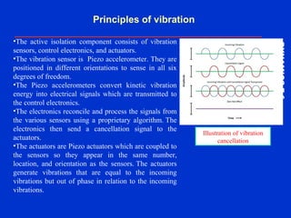
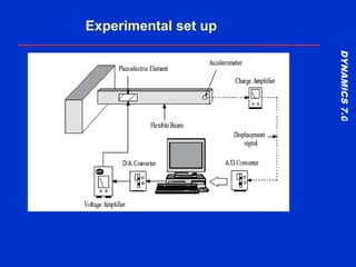
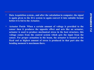
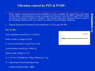
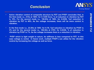
PVDF as an actuator
DYNAMICS7.0DYNAMICS7.0
Training Manual
Displacement and block force by PVDF
• Generally, Piezo film actuator designs, depend on the
application requirements such as operating speed,
displacement, generated force, and available electrical
power.
• When a voltage is applied to a sheet of Piezo film, it
causes the film to change dimensions due to the
attraction or repulsion of internal dipoles to the applied
field. With one voltage polarity is applied, the Piezo
film becomes thinner, longer and wider. The opposite
polarity causes the film to contract in length and width
and become thicker. An ac voltage causes the film to
"vibrate".
DYNAMICS7.0DYNAMICS7.0
Training Manual
The amount of deformation is given by the piezoelectric "d3n"
constant:
• For length change:
– Δ l= change in film length in meters
– L=original film length in meters
– d31= piezoelectric coefficient for length (n=1 direction) change in
meters per volt
– V=applied voltage across the thickness (t)
• For width change :
– Δ l = change in film length in meters
– d32= piezoelectric coefficient for length ( n=1 direction)change in
meters per volt
• For thickness change :
– d33= piezoelectric coefficient for length (n=3 direction) change in meters per volt
DYNAMICS7.0DYNAMICS7.0
Training Manual
Comparing with Numerical calculation
and Ansys results
Where δ= displacement
n=number of layers
d33
=Piezoelectric charge coefficient C/N
Ev= Voltage
Numerical calculation:
The blocking force Fmax
is the maximum force generated by the actuator. This
force is achieved when the displacement of the actuator is completely blocked, i.e. it
works against a load with an infinitely high stiffness. Since such stiffness does not
exist in reality, the blocking force is measured as shown in above equation.
The actuator length before operation is recorded. The actuator is displaced
without a load to the nominal displacement and then pushed back to the initial
position with an increasing external force. The force required for this is the blocking
force.
DYNAMICS7.0DYNAMICS7.0
Training Manual
Ansys results
Displacement 0.0169µ
DYNAMICS7.0DYNAMICS7.0
Training Manual
Conclusion:
• Block force calculated is 1420N
• Block force obtained is 1366N from Ansys
• Calculated deflection is 0.011microns
• Deflection from Ansys 0.0169microns
Note: Experiment should carry out to validate the results obtained
from numerical and Ansys.
Active vibration control
DYNAMICS7.0DYNAMICS7.0
Training Manual
• Active vibration control also called active vibration cancellation
isolation systems that dynamically react to incoming vibrations.
That is it senses the incoming vibrations and react to them.
• There are two types of active vibration cancellation systems
– Feed forward system: for regular periodic vibrations
– Feedback system: have a sensing mechanism which senses
incoming vibrations and an actuator which reacts to these
vibrations, either by tuning an isolator to reduce the incoming
vibrations or creating a signal which cancels them out.
DYNAMICS7.0DYNAMICS7.0
Training Manual
Principles of vibration
•The active isolation component consists of vibration
sensors, control electronics, and actuators.
•The vibration sensor is Piezo accelerometer. They are
positioned in different orientations to sense in all six
degrees of freedom.
•The Piezo accelerometers convert kinetic vibration
energy into electrical signals which are transmitted to
the control electronics.
•The electronics reconcile and process the signals from
the various sensors using a proprietary algorithm. The
electronics then send a cancellation signal to the
actuators.
•The actuators are Piezo actuators which are coupled to
the sensors so they appear in the same number,
location, and orientation as the sensors. The actuators
generate vibrations that are equal to the incoming
vibrations but out of phase in relation to the incoming
vibrations.
Illustration of vibration
cancellation
DYNAMICS7.0DYNAMICS7.0
Training Manual
Experimental set up
DYNAMICS7.0DYNAMICS7.0
Training Manual
• Aluminum Beam- This is the object on which the experiments are
done and our findings will be based. It is a simple beam with a
certain density and strength and dimension (31×2.5×0.5) cm.
• Set Table- As the beam has to be made a cantilever beam hence
we need to clamp it on set table, a set table is a modern clamping
apparatus on which we can make adjustments and move it in any
axis, even the rotation of the beam is possible.
• The standard experimental setup for the active
vibration control consists of several parts described
below:-
DYNAMICS7.0DYNAMICS7.0
Training Manual
• Accelerometer: this sensor sense or capture the vibration generated by
shaker and feed back to the actuator.
• Function Generator – An electronic function generator is used to generate
a function usually sinusoidal, Square or triangular wave form, the profile
of wave form generated lets us induce similar kind of vibration In the
beam.
• Amplifier- the signal received from the function generator is very weak
and is not enough to drive the exciter, hence the function generator is
coupled with an amplifier where the signals are amplified and finally fed
to the exciter.
• A/D convertor : A/D system is responsible for the encryption of the
input/output system, the signal which we receive form the sensor is an
electrical signal, and is not compatible with the computer, hence the A/D
system is used to convert this signal into acceptable form and then fed to
the computer
DYNAMICS7.0DYNAMICS7.0
Training Manual
• Data Acquisition system-, and after the calculation in computer, the signal
is again given to the D/A system to again convert it into suitable format
before it is fed to the Actuator.
• Actuator Patch- When a certain amount of voltage is provided to the
sensor then it produces the opposite effect and acts like an actuator,
actuator is used to produce mechanical stress in the host structure, this
voltage comes from the control system which gets the input from the
sensor. For proper actuation in the beam, the actuator is located at the
fixed end as highest amount of stress is produced in that part also the
bending moment is maximum there.
DYNAMICS7.0DYNAMICS7.0
Training Manual
• When signal is processing the power amplifier is used to amplify the signal that is the input
for the shaker. Accelerometer is used to capture the vibration. Here the PZT and PVDF which
is used as an actuator control the vibration. The actuators generate vibrations that are equal to
the incoming vibrations but out of phase in relation to the incoming vibrations.
• Natural frequencies obtained for the cantilever is 21 Hz and 106.5Hz
For 21 Hz.
Force transducer sensitivity is 112mV/N
Peak to peak is voltage 0.15mV
F= 0.15/10=0.015mV/112mV/N=0.133N
Accelerometer sensitivity is 99mV/g
Peak to peak voltage is 1.7V
A=1.7V/10=1.7X1000/10=170mV/99mV/g=1.71g
% = Open loop-Closed loop/Open loop
= 0.0043-0.0035/0.0043 =18%
Vibration control by PZT & PVDF:
DYNAMICS7.0DYNAMICS7.0
Training Manual
Graph for For 21 Hz
DYNAMICS7.0DYNAMICS7.0
Training Manual
For 106.8Hz
Force transducer sensitivity is 112mV/N
Peak to peak is voltage 40mV
F= 40/10=4mV/112mV/N=0.035N
Accelerometer sensitivity is 99mV/g
Peak to peak voltage is 5.12V
A=5.12V/10=5.12X1000/10
=512mV/99mV/g=5.17g
• Open loop (with no control): X = 106.187
Y = 0.025g2/Hz
• Closed loop: X = 106.195
Y = 0.013g2/Hz
% = Open loop-Closed loop/Open loop
= 0.025-0.013/0.025
=48%
DYNAMICS7.0DYNAMICS7.0
Training Manual
• Natural frequencies for PVDF attached cantilever beam is 23.5Hz & 106.5
• At 23.5Hz
Force transducer sensitivity is 112mV/N
Peak to peak is voltage 120mV
– F= 120/10=12mV/112mV/N=0.1N
Accelerometer sensitivity is 99mV/g
Peak to peak voltage is 8.48V
– A=8.48V/10=8.48X1000/10=848mV/99mV/g=8.56g
% = Open loop-Closed loop/Open loop
= 0.04567-0.0443/0.04567
=3%
Vibration control by PVDF
DYNAMICS7.0DYNAMICS7.0
Training Manual
At 23.5 Hz
DYNAMICS7.0DYNAMICS7.0
Training Manual
At 106.5Hz
Force transducer sensitivity is 112mV/N
Peak to peak is voltage 38mV
F= 38/10=3.8mV/112mV/N=0.033N
Accelerometer sensitivity is 99mV/g
Peak to peak voltage is 5.8V
A=5.8V/10=5.8X1000/10=580mV/99mV/g=5.85g
% = Open loop-Closed loop/Open loop
= 0.01842-0.017/0.01842
=7%
DYNAMICS7.0DYNAMICS7.0
Training Manual
% of reduction vibration in both PZT and
PVDF is shown below
DYNAMICS7.0DYNAMICS7.0
Training Manual
Conclusion
• Active vibration control of composite structure by PZT and PVDF concludes that, in
the first mode i.e., 21Hz at 160V, for 0.133N force, % of reduction in vibration by PZT
is 18%. For the second mode i.e., 106.8Hz at 196V, for 0.035N, %of reduction in
vibration by PZT is 48%. As the voltage increases, there will be more control in
vibration.
• In the first mode i.e., 23.5Hz at 150V, for 0.1N, %of reduction in vibration by PVDF is
3% and for the second mode i.e., 106.5Hz at 370V, for 0.033N, % of reduction in
vibration by PVDF is 7%. As the voltage increases there is a reduction in vibration.
• PVDF which is light weight in nature, its stiffness is less compared to PZT. In this
case voltage is varied. In future work, multiple PVDF’s can utilize for the vibration
control by increasing the voltage as well as force.

Active vibration control

  • 1.
    PVDF as anactuator
  • 2.
    DYNAMICS7.0DYNAMICS7.0 Training Manual Displacement andblock force by PVDF • Generally, Piezo film actuator designs, depend on the application requirements such as operating speed, displacement, generated force, and available electrical power. • When a voltage is applied to a sheet of Piezo film, it causes the film to change dimensions due to the attraction or repulsion of internal dipoles to the applied field. With one voltage polarity is applied, the Piezo film becomes thinner, longer and wider. The opposite polarity causes the film to contract in length and width and become thicker. An ac voltage causes the film to "vibrate".
  • 3.
    DYNAMICS7.0DYNAMICS7.0 Training Manual The amountof deformation is given by the piezoelectric "d3n" constant: • For length change: – Δ l= change in film length in meters – L=original film length in meters – d31= piezoelectric coefficient for length (n=1 direction) change in meters per volt – V=applied voltage across the thickness (t) • For width change : – Δ l = change in film length in meters – d32= piezoelectric coefficient for length ( n=1 direction)change in meters per volt • For thickness change : – d33= piezoelectric coefficient for length (n=3 direction) change in meters per volt
  • 4.
    DYNAMICS7.0DYNAMICS7.0 Training Manual Comparing withNumerical calculation and Ansys results Where δ= displacement n=number of layers d33 =Piezoelectric charge coefficient C/N Ev= Voltage Numerical calculation: The blocking force Fmax is the maximum force generated by the actuator. This force is achieved when the displacement of the actuator is completely blocked, i.e. it works against a load with an infinitely high stiffness. Since such stiffness does not exist in reality, the blocking force is measured as shown in above equation. The actuator length before operation is recorded. The actuator is displaced without a load to the nominal displacement and then pushed back to the initial position with an increasing external force. The force required for this is the blocking force.
  • 5.
  • 6.
    DYNAMICS7.0DYNAMICS7.0 Training Manual Conclusion: • Blockforce calculated is 1420N • Block force obtained is 1366N from Ansys • Calculated deflection is 0.011microns • Deflection from Ansys 0.0169microns Note: Experiment should carry out to validate the results obtained from numerical and Ansys.
  • 7.
  • 8.
    DYNAMICS7.0DYNAMICS7.0 Training Manual • Activevibration control also called active vibration cancellation isolation systems that dynamically react to incoming vibrations. That is it senses the incoming vibrations and react to them. • There are two types of active vibration cancellation systems – Feed forward system: for regular periodic vibrations – Feedback system: have a sensing mechanism which senses incoming vibrations and an actuator which reacts to these vibrations, either by tuning an isolator to reduce the incoming vibrations or creating a signal which cancels them out.
  • 9.
    DYNAMICS7.0DYNAMICS7.0 Training Manual Principles ofvibration •The active isolation component consists of vibration sensors, control electronics, and actuators. •The vibration sensor is Piezo accelerometer. They are positioned in different orientations to sense in all six degrees of freedom. •The Piezo accelerometers convert kinetic vibration energy into electrical signals which are transmitted to the control electronics. •The electronics reconcile and process the signals from the various sensors using a proprietary algorithm. The electronics then send a cancellation signal to the actuators. •The actuators are Piezo actuators which are coupled to the sensors so they appear in the same number, location, and orientation as the sensors. The actuators generate vibrations that are equal to the incoming vibrations but out of phase in relation to the incoming vibrations. Illustration of vibration cancellation
  • 10.
  • 11.
    DYNAMICS7.0DYNAMICS7.0 Training Manual • AluminumBeam- This is the object on which the experiments are done and our findings will be based. It is a simple beam with a certain density and strength and dimension (31×2.5×0.5) cm. • Set Table- As the beam has to be made a cantilever beam hence we need to clamp it on set table, a set table is a modern clamping apparatus on which we can make adjustments and move it in any axis, even the rotation of the beam is possible. • The standard experimental setup for the active vibration control consists of several parts described below:-
  • 12.
    DYNAMICS7.0DYNAMICS7.0 Training Manual • Accelerometer:this sensor sense or capture the vibration generated by shaker and feed back to the actuator. • Function Generator – An electronic function generator is used to generate a function usually sinusoidal, Square or triangular wave form, the profile of wave form generated lets us induce similar kind of vibration In the beam. • Amplifier- the signal received from the function generator is very weak and is not enough to drive the exciter, hence the function generator is coupled with an amplifier where the signals are amplified and finally fed to the exciter. • A/D convertor : A/D system is responsible for the encryption of the input/output system, the signal which we receive form the sensor is an electrical signal, and is not compatible with the computer, hence the A/D system is used to convert this signal into acceptable form and then fed to the computer
  • 13.
    DYNAMICS7.0DYNAMICS7.0 Training Manual • DataAcquisition system-, and after the calculation in computer, the signal is again given to the D/A system to again convert it into suitable format before it is fed to the Actuator. • Actuator Patch- When a certain amount of voltage is provided to the sensor then it produces the opposite effect and acts like an actuator, actuator is used to produce mechanical stress in the host structure, this voltage comes from the control system which gets the input from the sensor. For proper actuation in the beam, the actuator is located at the fixed end as highest amount of stress is produced in that part also the bending moment is maximum there.
  • 14.
    DYNAMICS7.0DYNAMICS7.0 Training Manual • Whensignal is processing the power amplifier is used to amplify the signal that is the input for the shaker. Accelerometer is used to capture the vibration. Here the PZT and PVDF which is used as an actuator control the vibration. The actuators generate vibrations that are equal to the incoming vibrations but out of phase in relation to the incoming vibrations. • Natural frequencies obtained for the cantilever is 21 Hz and 106.5Hz For 21 Hz. Force transducer sensitivity is 112mV/N Peak to peak is voltage 0.15mV F= 0.15/10=0.015mV/112mV/N=0.133N Accelerometer sensitivity is 99mV/g Peak to peak voltage is 1.7V A=1.7V/10=1.7X1000/10=170mV/99mV/g=1.71g % = Open loop-Closed loop/Open loop = 0.0043-0.0035/0.0043 =18% Vibration control by PZT & PVDF:
  • 15.
  • 16.
    DYNAMICS7.0DYNAMICS7.0 Training Manual For 106.8Hz Forcetransducer sensitivity is 112mV/N Peak to peak is voltage 40mV F= 40/10=4mV/112mV/N=0.035N Accelerometer sensitivity is 99mV/g Peak to peak voltage is 5.12V A=5.12V/10=5.12X1000/10 =512mV/99mV/g=5.17g • Open loop (with no control): X = 106.187 Y = 0.025g2/Hz • Closed loop: X = 106.195 Y = 0.013g2/Hz % = Open loop-Closed loop/Open loop = 0.025-0.013/0.025 =48%
  • 17.
    DYNAMICS7.0DYNAMICS7.0 Training Manual • Naturalfrequencies for PVDF attached cantilever beam is 23.5Hz & 106.5 • At 23.5Hz Force transducer sensitivity is 112mV/N Peak to peak is voltage 120mV – F= 120/10=12mV/112mV/N=0.1N Accelerometer sensitivity is 99mV/g Peak to peak voltage is 8.48V – A=8.48V/10=8.48X1000/10=848mV/99mV/g=8.56g % = Open loop-Closed loop/Open loop = 0.04567-0.0443/0.04567 =3% Vibration control by PVDF
  • 18.
  • 19.
    DYNAMICS7.0DYNAMICS7.0 Training Manual At 106.5Hz Forcetransducer sensitivity is 112mV/N Peak to peak is voltage 38mV F= 38/10=3.8mV/112mV/N=0.033N Accelerometer sensitivity is 99mV/g Peak to peak voltage is 5.8V A=5.8V/10=5.8X1000/10=580mV/99mV/g=5.85g % = Open loop-Closed loop/Open loop = 0.01842-0.017/0.01842 =7%
  • 20.
    DYNAMICS7.0DYNAMICS7.0 Training Manual % ofreduction vibration in both PZT and PVDF is shown below
  • 21.
    DYNAMICS7.0DYNAMICS7.0 Training Manual Conclusion • Activevibration control of composite structure by PZT and PVDF concludes that, in the first mode i.e., 21Hz at 160V, for 0.133N force, % of reduction in vibration by PZT is 18%. For the second mode i.e., 106.8Hz at 196V, for 0.035N, %of reduction in vibration by PZT is 48%. As the voltage increases, there will be more control in vibration. • In the first mode i.e., 23.5Hz at 150V, for 0.1N, %of reduction in vibration by PVDF is 3% and for the second mode i.e., 106.5Hz at 370V, for 0.033N, % of reduction in vibration by PVDF is 7%. As the voltage increases there is a reduction in vibration. • PVDF which is light weight in nature, its stiffness is less compared to PZT. In this case voltage is varied. In future work, multiple PVDF’s can utilize for the vibration control by increasing the voltage as well as force.

Editor's Notes

  • #15 This results in cancellation of the incoming noise, leaving the load on top of the system undisturbed. This process occurs within 5 – 20 milliseconds of a vibration entering the system. This results in cancellation of the incoming noise, leaving the load on top of the system undisturbed. This process occurs within 5 – 20 milliseconds of a vibration entering the system.