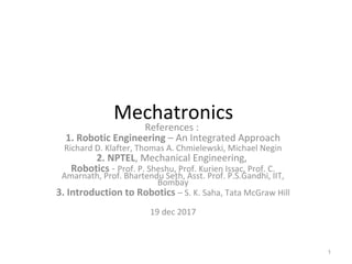
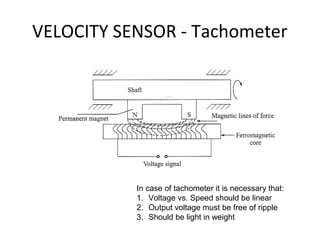
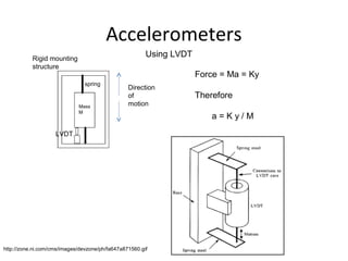
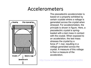
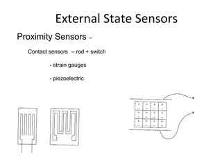
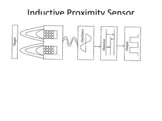
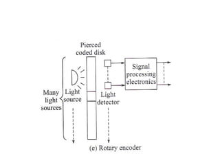
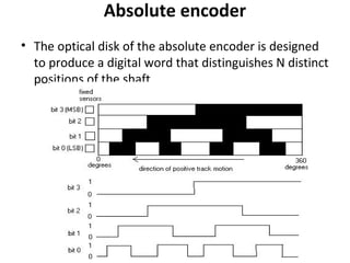
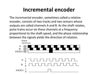
Mechatronics
References :
1. Robotic Engineering – An Integrated Approach
Richard D. Klafter, Thomas A. Chmielewski, Michael Negin
2. NPTEL, Mechanical Engineering,
Robotics - Prof. P. Sheshu, Prof. Kurien Issac, Prof. C.
Amarnath, Prof. Bhartendu Seth, Asst. Prof. P.S.Gandhi, IIT,
Bombay
3. Introduction to Robotics – S. K. Saha, Tata McGraw Hill
19 dec 2017
1
http://www.linear.com/solutions/1180
VELOCITY SENSOR - Tachometer
In case of tachometer it is necessary that:
1. Voltage vs. Speed should be linear
2. Output voltage must be free of ripple
3. Should be light in weight
VELOCITY SENSOR – Hall Effect
sensor
Hall Effect Sensor
This component can be used in a circuit to open
and close a contact when exposed to
alternating N and S poles of a magnet. Will also
work if exposed to the same pole on alternative
sides of the sensor.
Many uses including:
Counting revolutions, oscillations, or sequences
Turning LEDs, alarms, or other devices on/off
Detecting presence of magnetized materials
Intruder/theft alarms
Monitor start/stop of a moving process
Robotic effects and magic tricks!
Source: http://www.lessemf.com
Accelerometers
LVDT
Mass
M
spring
Direction
of
motion
Rigid mounting
structure
Force = Ma = Ky
Therefore
a = K y / M
http://zone.ni.com/cms/images/devzone/ph/fa647a871560.gif
Using LVDT
Accelerometers
The piezoelectric accelerometer is
based on a property exhibited by
certain crystals where a voltage is
generated across the crystal when
stressed. For accelerometers, the
principle is shown in figure. Here, a
piezoelectric crystal is spring-
loaded with a test mass in contact
with the crystal. When exposed to
an acceleration, the test mass
stresses the crystal by a
force (F = ma), resulting in a
voltage generated across the
crystal. A measure of this voltage
is then a measure of the
acceleration.
http://zone.ni.com/devzone/cda/ph/p/id/284
Accelerometer
Digital Accelerometer
Example: LIS302 is a 3-axis digital accelerometer
■ 2.16V to 3.6V supply voltage
Application
■ Free-Fall detection
■ Motion activated functions
■ Gaming and virtual reality input devices
■ Vibration monitoring and compensation
Description
The LIS302DL is an ultra compact low-power
three axes linear accelerometer. It includes a
sensing element and an IC interface able to
provide the measured acceleration to the
external World
http://www.st.com/
21 Dec 2017
External State Sensors
Proximity Sensors –
Contact sensors – rod + switch
- strain gauges
- piezoelectric
External Sensors
Proximity Sensors -
Non-contact type
- reflected light sensors
*two different object positions produce same
voltage – giving incorrect value
* ambient light
* sensitivity depends on reflectivity of object
* errors due to variations in light-source output,
drift in detector characteristics, environmentally aused
changes in reflectivity of object
Inductive Proximity Sensor
http://www.slideshare.net/satyanaveenvyas/proximity-sensors
Optical proximity sensors
Davis Instruments
Ecdcontrols.com
Fibre – Optic Scanning sensors
• Opposed or beam break configuration
• Retroreflective
• Reflective
Digital Sensors for Motion
Measurement
Ref: Introduction to Mechatronics and Measurement Systems, Histand & Alciatore,
1999 McGraw Hill
Digital Encoder
• A digital optical encoder converts motion into
a sequence of digital pulses.
• By decoding a set of bits, the pulses can be
converted to relative or absolute position
measurements.
• Encoders have both linear and rotary
configurations.
Rotary Optical Encoder
Absolute encoder
• The optical disk of the absolute encoder is designed
to produce a digital word that distinguishes N distinct
positions of the shaft.
Incremental encoder
The incremental encoder, sometimes called a relative
encoder, consists of two tracks and two sensors whose
outputs are called channels A and B. As the shaft rotates,
pulse trains occur on these channels at a frequency
proportional to the shaft speed, and the phase relationship
between the signals yields the direction of rotation.
Moire Fringe Transducer

Mechatronics sensors3.1

  • 1.
    Mechatronics References : 1. RoboticEngineering – An Integrated Approach Richard D. Klafter, Thomas A. Chmielewski, Michael Negin 2. NPTEL, Mechanical Engineering, Robotics - Prof. P. Sheshu, Prof. Kurien Issac, Prof. C. Amarnath, Prof. Bhartendu Seth, Asst. Prof. P.S.Gandhi, IIT, Bombay 3. Introduction to Robotics – S. K. Saha, Tata McGraw Hill 19 dec 2017 1
  • 2.
  • 3.
    VELOCITY SENSOR -Tachometer In case of tachometer it is necessary that: 1. Voltage vs. Speed should be linear 2. Output voltage must be free of ripple 3. Should be light in weight
  • 4.
    VELOCITY SENSOR –Hall Effect sensor
  • 5.
    Hall Effect Sensor Thiscomponent can be used in a circuit to open and close a contact when exposed to alternating N and S poles of a magnet. Will also work if exposed to the same pole on alternative sides of the sensor. Many uses including: Counting revolutions, oscillations, or sequences Turning LEDs, alarms, or other devices on/off Detecting presence of magnetized materials Intruder/theft alarms Monitor start/stop of a moving process Robotic effects and magic tricks! Source: http://www.lessemf.com
  • 6.
    Accelerometers LVDT Mass M spring Direction of motion Rigid mounting structure Force =Ma = Ky Therefore a = K y / M http://zone.ni.com/cms/images/devzone/ph/fa647a871560.gif Using LVDT
  • 7.
    Accelerometers The piezoelectric accelerometeris based on a property exhibited by certain crystals where a voltage is generated across the crystal when stressed. For accelerometers, the principle is shown in figure. Here, a piezoelectric crystal is spring- loaded with a test mass in contact with the crystal. When exposed to an acceleration, the test mass stresses the crystal by a force (F = ma), resulting in a voltage generated across the crystal. A measure of this voltage is then a measure of the acceleration. http://zone.ni.com/devzone/cda/ph/p/id/284
  • 8.
    Accelerometer Digital Accelerometer Example: LIS302is a 3-axis digital accelerometer ■ 2.16V to 3.6V supply voltage Application ■ Free-Fall detection ■ Motion activated functions ■ Gaming and virtual reality input devices ■ Vibration monitoring and compensation Description The LIS302DL is an ultra compact low-power three axes linear accelerometer. It includes a sensing element and an IC interface able to provide the measured acceleration to the external World http://www.st.com/
  • 9.
  • 10.
    External State Sensors ProximitySensors – Contact sensors – rod + switch - strain gauges - piezoelectric
  • 11.
    External Sensors Proximity Sensors- Non-contact type - reflected light sensors *two different object positions produce same voltage – giving incorrect value * ambient light * sensitivity depends on reflectivity of object * errors due to variations in light-source output, drift in detector characteristics, environmentally aused changes in reflectivity of object
  • 12.
  • 13.
  • 14.
    Optical proximity sensors DavisInstruments Ecdcontrols.com
  • 15.
    Fibre – OpticScanning sensors • Opposed or beam break configuration • Retroreflective • Reflective
  • 17.
    Digital Sensors forMotion Measurement Ref: Introduction to Mechatronics and Measurement Systems, Histand & Alciatore, 1999 McGraw Hill
  • 20.
    Digital Encoder • Adigital optical encoder converts motion into a sequence of digital pulses. • By decoding a set of bits, the pulses can be converted to relative or absolute position measurements. • Encoders have both linear and rotary configurations.
  • 21.
  • 22.
    Absolute encoder • Theoptical disk of the absolute encoder is designed to produce a digital word that distinguishes N distinct positions of the shaft.
  • 23.
    Incremental encoder The incrementalencoder, sometimes called a relative encoder, consists of two tracks and two sensors whose outputs are called channels A and B. As the shaft rotates, pulse trains occur on these channels at a frequency proportional to the shaft speed, and the phase relationship between the signals yields the direction of rotation.
  • 24.

Editor's Notes

  • #3 An LVDT transformer is exited with a fixed frequency sine wave. The distance of displacement of the movable core will change the amplitude of the transformer output which is is converted to a dc voltage by the LT1967 True RMS converter. The direction of the core movement is indicated by the phase shift of the sine wave and is detected by a simple phase comparator circuit.