The document provides an overview of chilled beam systems, including their design, components, and applications for heating and cooling in large buildings. It explains different types of chilled beams, such as active and passive, and outlines their benefits and limitations, emphasizing energy savings and thermal comfort. Specific design and operational considerations are discussed, alongside practical applications in various settings.

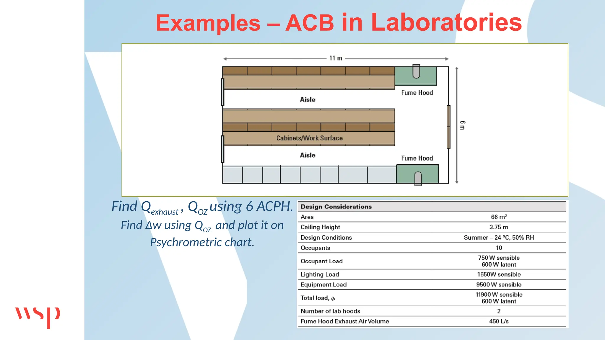
![Examples – ACB in Laboratories
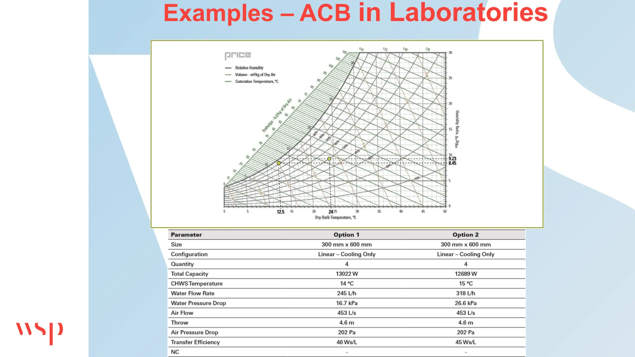
Qexhaust = max[450 l/s,{(11 m)*(6 m)*(3.75 m)*(6 acph)*h/3.6}]
= max(450 l/s, 413 l/s)
= 450 l/s.
QOZ = (1-20%)*Qexhaust = 360 l/s = Qs
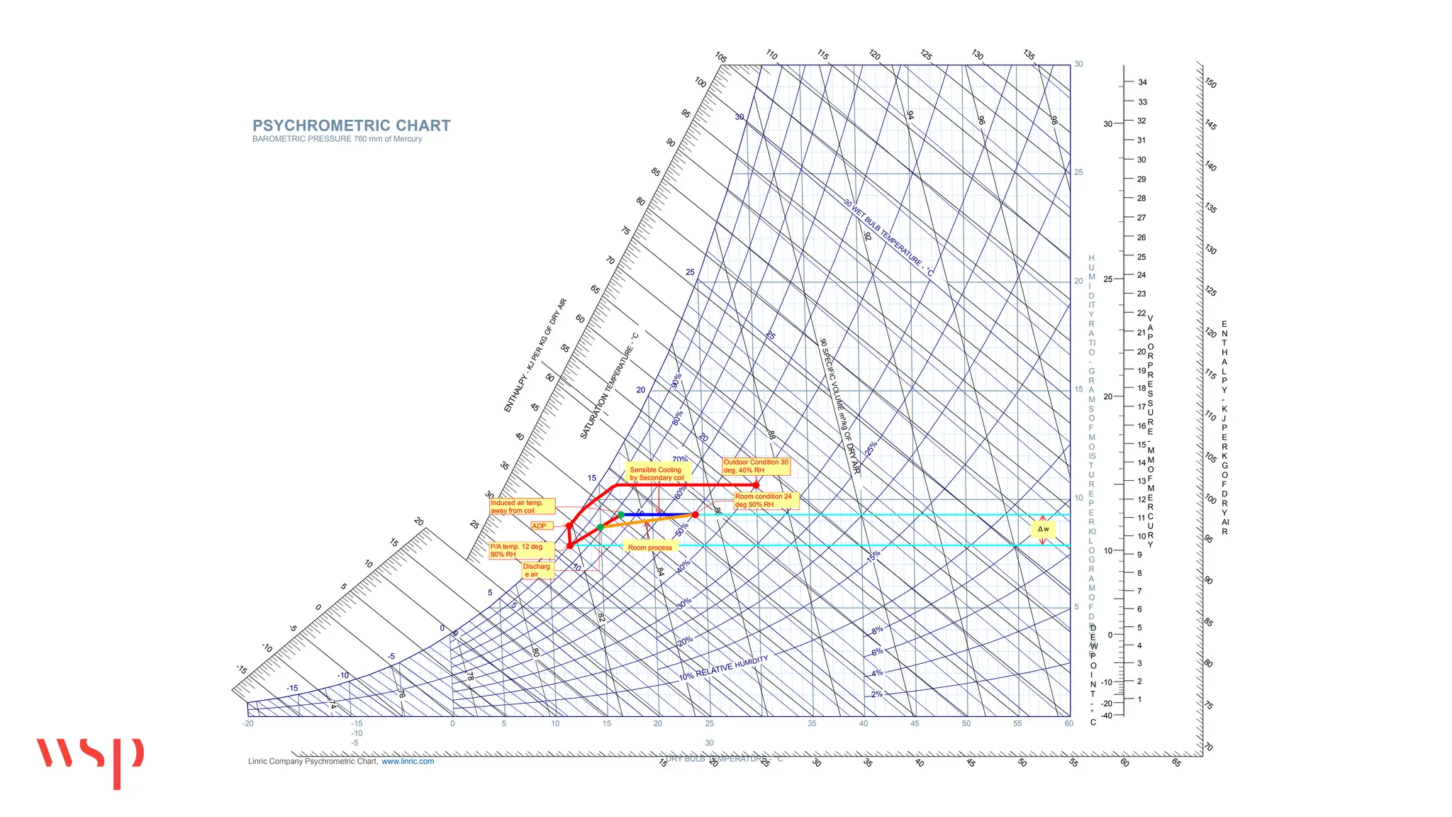
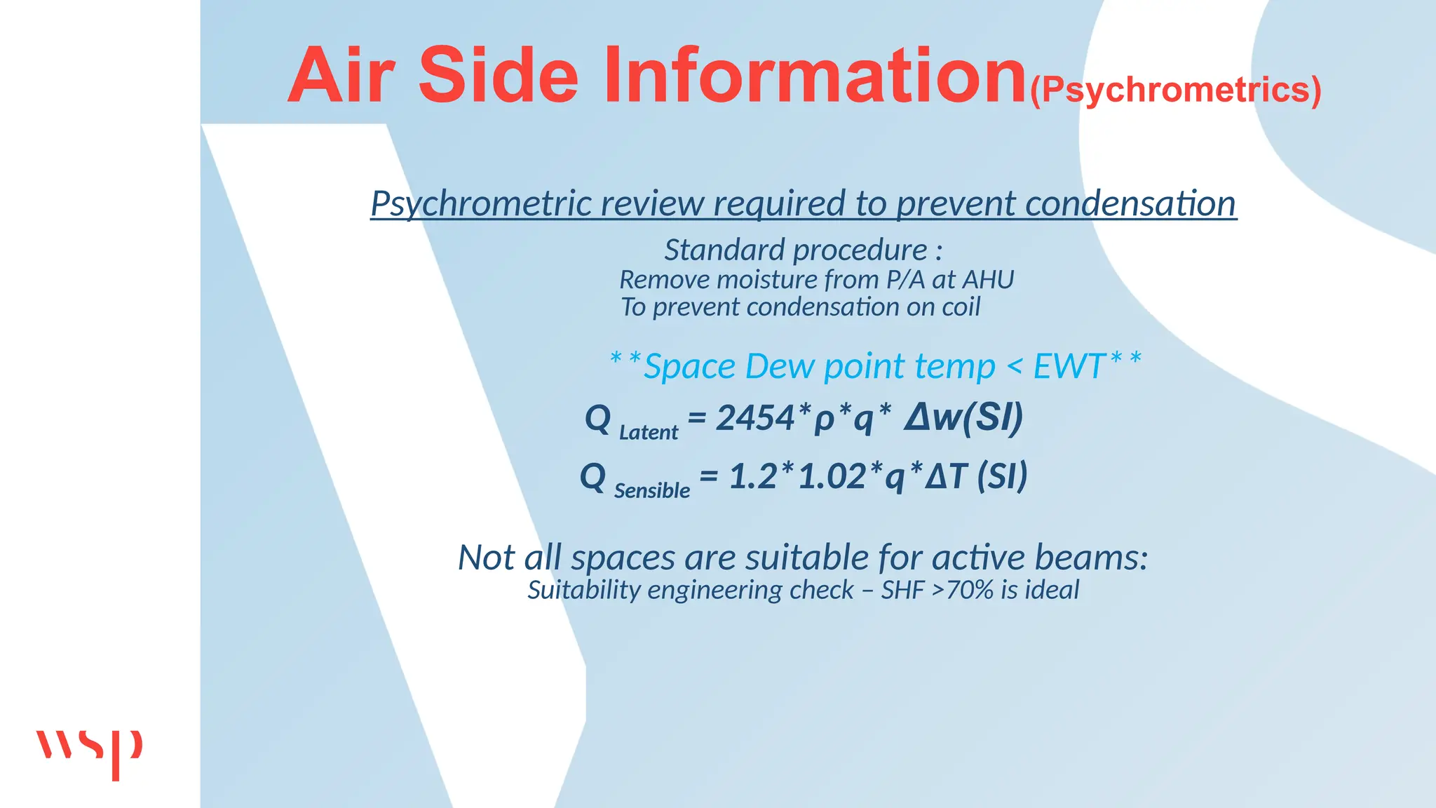
QL = 2500*ρ*Qs* Δw
ΔW = 0.55 g/kg
at 240
C, 50%RH humidity ratio is 9.5 g/kg
Ws = 9.5 – 0.55 = 8.95 g/kg (plotting it in psychrometric chart)](https://image.slidesharecdn.com/2007-chilledbeampresentation-241029064235-34185132/75/Chilled-Beam-System-Design-and-Applications-24-2048.jpg)