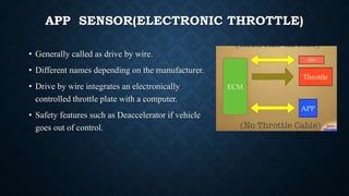
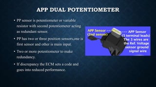
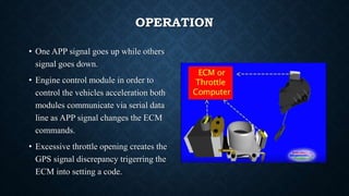
ACCELERATOR PEDAL
POSITION SENSOR
Video link :https://youtu.be/pjSLQJRZ7UA
Presented by
Sakthigurusamy.S
INTRODUCTION
The APP sensor is fixed to the throttle body of the electronic throttle control
system with intelligence (ETCSi).
The functional principle to the AAP sensor involves conversion of the
accelerator pedal movement into a voltage signal.
The accelerator position information is transferred to the throttle actuator control
(TAC) module and the powertrain control module (PCM).
The accelerator position sensor is made up of two individual sensors, with both
sensors designed to have individual sensor return wiring and each have a varying
voltage range.
CONTD…
The PCM system receives and processes the electrical signals from the ACC
sensors along with signals from the direct current (DC) motor, which sets the
throttle plate via a throttle cable.
As the air travels through the throttle passage to the intake manifold, it activates
airflow sensors that manipulates the engine control unit and forces fuel into the
fluid injector system.
The AAP sensor system is typically known as the ‘drive by wire’ system and, as
mentioned, delivers information to the engine control module systems about the
accelerator pedal position in addition to the information about the speed at which
the driver is pushing on the gas pedal.
WORKING PRINCIPLE
 The application of alternating voltage to the
transmission coil produces a magnetic field
which induces voltages in the receiver
coils.
 A current is also induced in the rotor
conductive loops which, in turn, influences
the magnetic field of the receiver coils.
 Voltage amplitudes are produced depending
on the position of the rotor relative to the
receiver coils in the stator.
 These are processed in an electronic
evaluation unit and then transmitted to the
control unit in the form of direct-current
voltage.
APP SENSOR(ELECTRONIC THROTTLE)
• Generally called as drive by wire.
• Different names depending on the manufacturer.
• Drive by wire integrates an electronically
controlled throttle plate with a computer.
• Safety features such as Deaccelerator if vehicle
goes out of control.
FEATURES
• This sensor is importance to drive by wire
system.
• ECM with accelerator pedal position as well as
rate of change or how fast the driver is pushing
the gas pedal
• ECM with cruise control,automatic idle
adjustment and deaccelerator as safety.
APP DUAL POTENTIOMETER
• PP sensor is potentiometer or variable
resistor with second potentiometer acting
as redundant sensor.
• PP has two or three position sensors,one is
first sensor and other is main input.
• Two or more potentiometer to make
redundancy.
• If discrepancy the ECM sets a code and
goes into reduced performance.
OPERATION MODE
• Reverse mode:
• ECM changes the accelerator pattern of the
vehicle when backing up.
• If PP sensor fails,ECM cuts rejector
pulsation every other revolution is the event
of PP failure reduces performance
LIMP IN MODE
• APP 1&2 discrepancy will set the system in Limp in
mode.
• If reference voltage or ground is lost to one of the
potentiometer, others are still able to perform the
operation.
• The series of potentiometer within PP sensor are
wired differently for redundancy.
• Understanding the wiring pattern is important for
diagnosis.
OPERATION
• One APP signal goes up while others
signal goes down.
• Engine control module in order to
control the vehicles acceleration both
modules communicate via serial data
line as APP signal changes the ECM
commands.
• Excessive throttle opening creates the
GPS signal discrepancy trigerring the
ECM into setting a code.
SYMPTOMS OF A FAULTY
If the accelerator pedal sensor fails, the following fault symptoms may occur:
Increased engine idling speed
Vehicle does not respond if the accelerator pedal is pressed
Vehicle switches to "limp-home mode"
Engine warning light in the cockpit illuminates
CAUSE OF FAILURE
A failure could have a number of different causes:
Damaged cables or connections on the accelerator pedal sensor
Missing voltage and ground supply
Faulty electronic evaluation unit in the sensor
THANK YOU

Accelerator pedal position sensor

  • 1.
    ACCELERATOR PEDAL POSITION SENSOR Videolink :https://youtu.be/pjSLQJRZ7UA Presented by Sakthigurusamy.S
  • 2.
    INTRODUCTION The APP sensoris fixed to the throttle body of the electronic throttle control system with intelligence (ETCSi). The functional principle to the AAP sensor involves conversion of the accelerator pedal movement into a voltage signal. The accelerator position information is transferred to the throttle actuator control (TAC) module and the powertrain control module (PCM). The accelerator position sensor is made up of two individual sensors, with both sensors designed to have individual sensor return wiring and each have a varying voltage range.
  • 3.
    CONTD… The PCM systemreceives and processes the electrical signals from the ACC sensors along with signals from the direct current (DC) motor, which sets the throttle plate via a throttle cable. As the air travels through the throttle passage to the intake manifold, it activates airflow sensors that manipulates the engine control unit and forces fuel into the fluid injector system. The AAP sensor system is typically known as the ‘drive by wire’ system and, as mentioned, delivers information to the engine control module systems about the accelerator pedal position in addition to the information about the speed at which the driver is pushing on the gas pedal.
  • 4.
    WORKING PRINCIPLE  Theapplication of alternating voltage to the transmission coil produces a magnetic field which induces voltages in the receiver coils.  A current is also induced in the rotor conductive loops which, in turn, influences the magnetic field of the receiver coils.  Voltage amplitudes are produced depending on the position of the rotor relative to the receiver coils in the stator.  These are processed in an electronic evaluation unit and then transmitted to the control unit in the form of direct-current voltage.
  • 5.
    APP SENSOR(ELECTRONIC THROTTLE) •Generally called as drive by wire. • Different names depending on the manufacturer. • Drive by wire integrates an electronically controlled throttle plate with a computer. • Safety features such as Deaccelerator if vehicle goes out of control.
  • 6.
    FEATURES • This sensoris importance to drive by wire system. • ECM with accelerator pedal position as well as rate of change or how fast the driver is pushing the gas pedal • ECM with cruise control,automatic idle adjustment and deaccelerator as safety.
  • 7.
    APP DUAL POTENTIOMETER •PP sensor is potentiometer or variable resistor with second potentiometer acting as redundant sensor. • PP has two or three position sensors,one is first sensor and other is main input. • Two or more potentiometer to make redundancy. • If discrepancy the ECM sets a code and goes into reduced performance.
  • 8.
    OPERATION MODE • Reversemode: • ECM changes the accelerator pattern of the vehicle when backing up. • If PP sensor fails,ECM cuts rejector pulsation every other revolution is the event of PP failure reduces performance
  • 9.
    LIMP IN MODE •APP 1&2 discrepancy will set the system in Limp in mode. • If reference voltage or ground is lost to one of the potentiometer, others are still able to perform the operation. • The series of potentiometer within PP sensor are wired differently for redundancy. • Understanding the wiring pattern is important for diagnosis.
  • 10.
    OPERATION • One APPsignal goes up while others signal goes down. • Engine control module in order to control the vehicles acceleration both modules communicate via serial data line as APP signal changes the ECM commands. • Excessive throttle opening creates the GPS signal discrepancy trigerring the ECM into setting a code.
  • 11.
    SYMPTOMS OF AFAULTY If the accelerator pedal sensor fails, the following fault symptoms may occur: Increased engine idling speed Vehicle does not respond if the accelerator pedal is pressed Vehicle switches to "limp-home mode" Engine warning light in the cockpit illuminates
  • 12.
    CAUSE OF FAILURE Afailure could have a number of different causes: Damaged cables or connections on the accelerator pedal sensor Missing voltage and ground supply Faulty electronic evaluation unit in the sensor
  • 13.