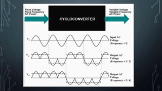
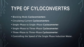
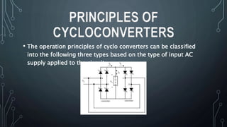
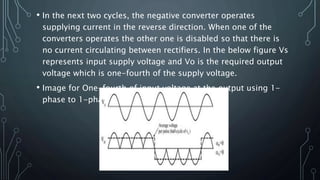
2. • Basically, cyclo-converters are AC to AC converters
and are used to vary the frequency of a supply to a
desired load frequency. These are naturally
commutated, direct frequency converters that use
naturally commutated thyristors . These are mainly
used in high power applications up to tens of
megawatts for frequency reduction.
INTRODUCTION
5. • Due to the DC-link storage element, there is the advantage that
both converter stages are to a large extent decoupled for
control purposes. Furthermore, a constant, AC line independent
input quantity exists for the PWM inverter stage, which results
in high utilization of the converter’s power capability. On the
other hand, the DC-link energy storage element has a relatively
large physical volume, and when electrolytic capacitors are
used, in the case of a voltage DC-link, there is potentially a
reduced system lifetime
DC LINK CONVERTERS
6. • converter uses an induction generator motor, in that it rotates
to transform single-phase utility power into three-
phase electricity. A rotary phase converter generates one line of
power from the induction generator motor and merges that
with two single-phase lines
CONVERTERS
7. • There are mainly two types of cycloconverters blocking mode
type and circulating mode type. When the load current is
positive, the positive converter supplies the required voltage,
and the negative converter is blocked. Suppose if the load
current is negative, then the negative converter supplies the
voltage and the positive converter is blocked. This operation is
called blocking mode operation. The cycloconverters which are
using this method are called blocking mode cycloconverters.
APPLICATION
CYLOCONVERTERS
8. • Blocking Mode Cyclocornverters:
• Circulating Current Cycloconverters:
• Single-Phase to Single-Phase Cycloconverter:
• Single-Phase to Three-Phase Cycloconverter:
• Three-Phase to Three-Phase Cycloconverter:
• Controlling the Speed of the Single Phase Induction Motor.
TYPE OF CYLOCONVERTRS
9. • Blocking mode cycloconverters don’t need any intergroup reactor
(IGR). Depends on the polarity, one of the converters is enabled.
The blocking mode operation has some advantages and
disadvantages over circulating mode operation. They don’t need
any reactors hence size and cost is less. Only one converter is in
conduction at all times rather than two.
• During delay time current stays at zero distorting the voltage and
current waveforms. This distortion means complex harmonic
patterns.
BLOCKING
MODE CYLOCONVERTRS
10. • Both the converters operate at all times in this case. The big
disadvantage is an IGR is needed. The number of devices
connecting to this is twice than of blocking current
cycloconverter .
CIRCULATING
CURRENT CYLOCONVERTRS
11. • The operation principles of cyclo converters can be classified
into the following three types based on the type of input AC
supply applied to the circuit.
PRINCIPLES OF
CYCLOCONVERTERS
12. • Understanding of operation principles of cyclo
converters should begin with single-phase to single-
phase cycloconverter. This converter is having back to
back connection of two full-wave rectifiers. Suppose for
getting one-fourth of input voltage at the output, for
the first two cycles of Vs the positive converter operates
supplying current to the load and it rectifies the input
voltage.
SINGLE-PHASE TO SINGLE-PHASE
CYCLOCONVERTER:
13. • In the next two cycles, the negative converter operates
supplying current in the reverse direction. When one of the
converters operates the other one is disabled so that there is
no current circulating between rectifiers. In the below figure Vs
represents input supply voltage and Vo is the required output
voltage which is one-fourth of the supply voltage.
• Image for One-fourth of input voltage at the output using 1-
phase to 1-phase Cycloconverte.
14. • Like as above converters, three-phase to single-phase cycloconverter
applies rectified voltage to the load. Positive Cycloconverters will
supply positive current only while negative converters will supply
negative current only. The cyclo converters can operate in four
quadrants as (+v, +i), (+v, -i) rectification modes and (-v, +i), (-v, -i)
inverting modes. The polarity of the current determines if the
positive or negative converter should be supplying power to the load.
When there is a change in current polarity, the converter previously
supplying current is disabled and the other one is enabled. During
the current polarity reversal, the average voltage supplied by both
the converters should be equal
SINGLE-PHASE TO THREE-PHASE
CYCLOCONVERTER:
15. • Two basic configurations are available for three-phase cyclo
converters such as delta and wye. If the outputs of the above
converter are connected in wye or delta and if the output
voltages are 120º phase-shifted the resulting converter is
three-phase to the three-phase converter. The three-phase
converters are mainly used in machine drive systems running
three-phase synchronous and induction machines.
THREE-PHASE TO THREE-PHASE
CYCLOCONVERTER:
16. • ingle-phase induction motors are widely used in many
applications. Improvements in its performance mean a great
saving in electrical energy consumption. A speed controller
based on cycloconverter is proposed.
• The above circuit diagram can be used to control the speed of a
single-phase induction motor in three steps by using cyclo
converters and thyristors. The circuit uses a thyristor controlled
cycloconverter which enabling the control of speed in steps of
an induction motor.
CONTROLLING THE SPEED
OF THE SINGLE PHASE
INDUCTION MOTOR.
17. • For the 8051 series of microcontrollers, a pair of slide switches
are provided to select the required speed range of operation of
induction motor. These switches are interfacing with the
microcontroller to deliver the pulses to trigger the SCRs in a
dual bridge. Thus the speed of the motor can be achieved in
three steps.
• Some other applications where Cycloconverters can be used are
cement mill drives, ship propulsion drives, Rolling mills, and
mine winders, washing machines, water pumps, and used in
industries as well. If any further more queries on this topic or
on the electrical and electronic projects leave the comments
section below.
19. •ADVANTAGES
• Efficiency is very high compared to other converters
• AC power at one frequency is directly converted to a lower frequency in a
single conversion
• If one of the SCR fails, the cyclo-converter operates with a distorted output
• In this converter, power transfer is possible from supply load and vice versa
at any power factor
• Dynamic response is good
• Smooth low-speed operation
ADVANTAGES AND DISADVANTAGES
OF CYCLOCONVERTER
20. •DISADVANTEGES
• Control circuit become complex so difficult to design
• The output frequency of the cycloconverter is 1/3th or 1/2th for
responsible
power output and efficiency
• Power factor is too much poor at large values of α
• More distortion at low frequencies