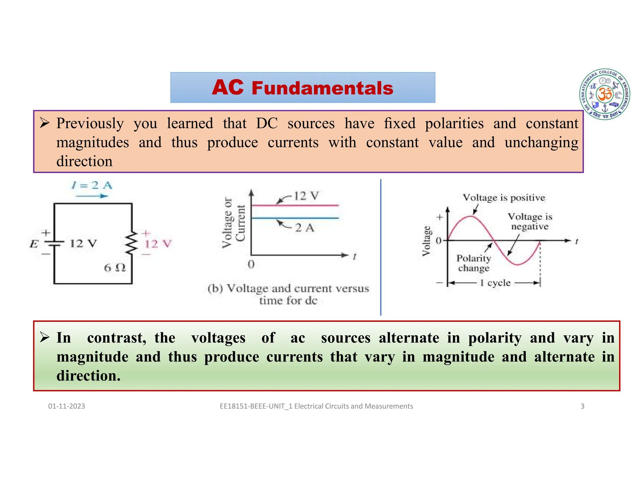
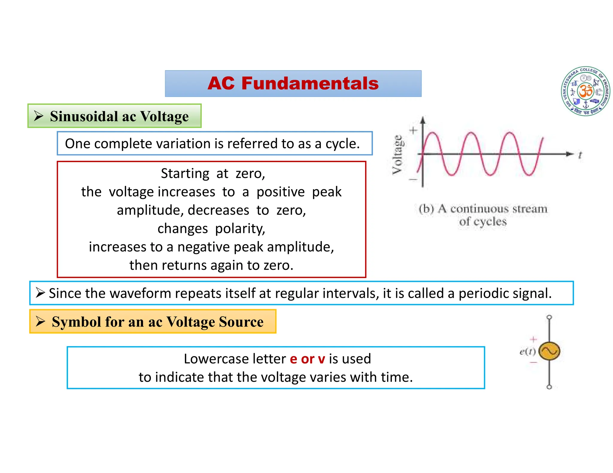
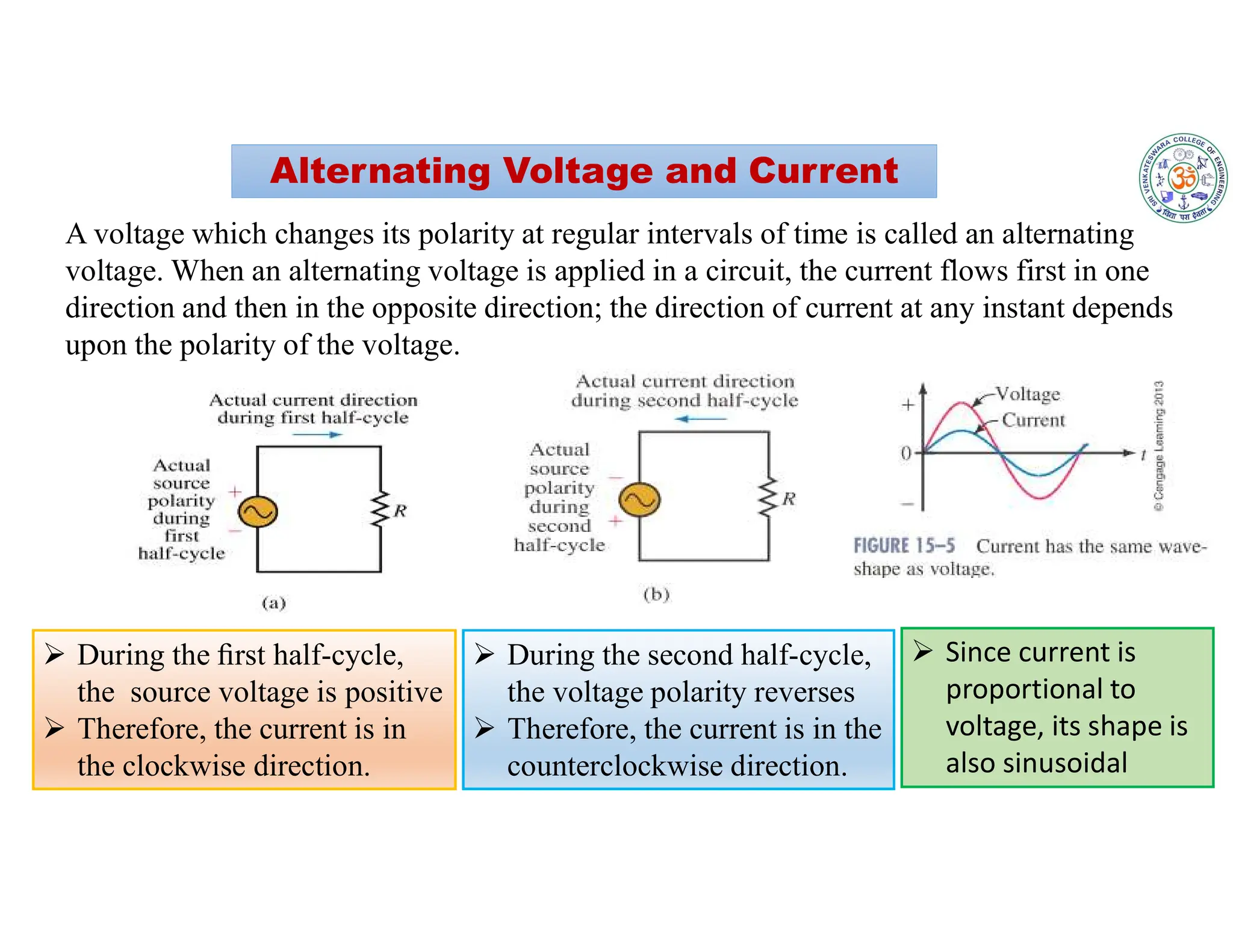
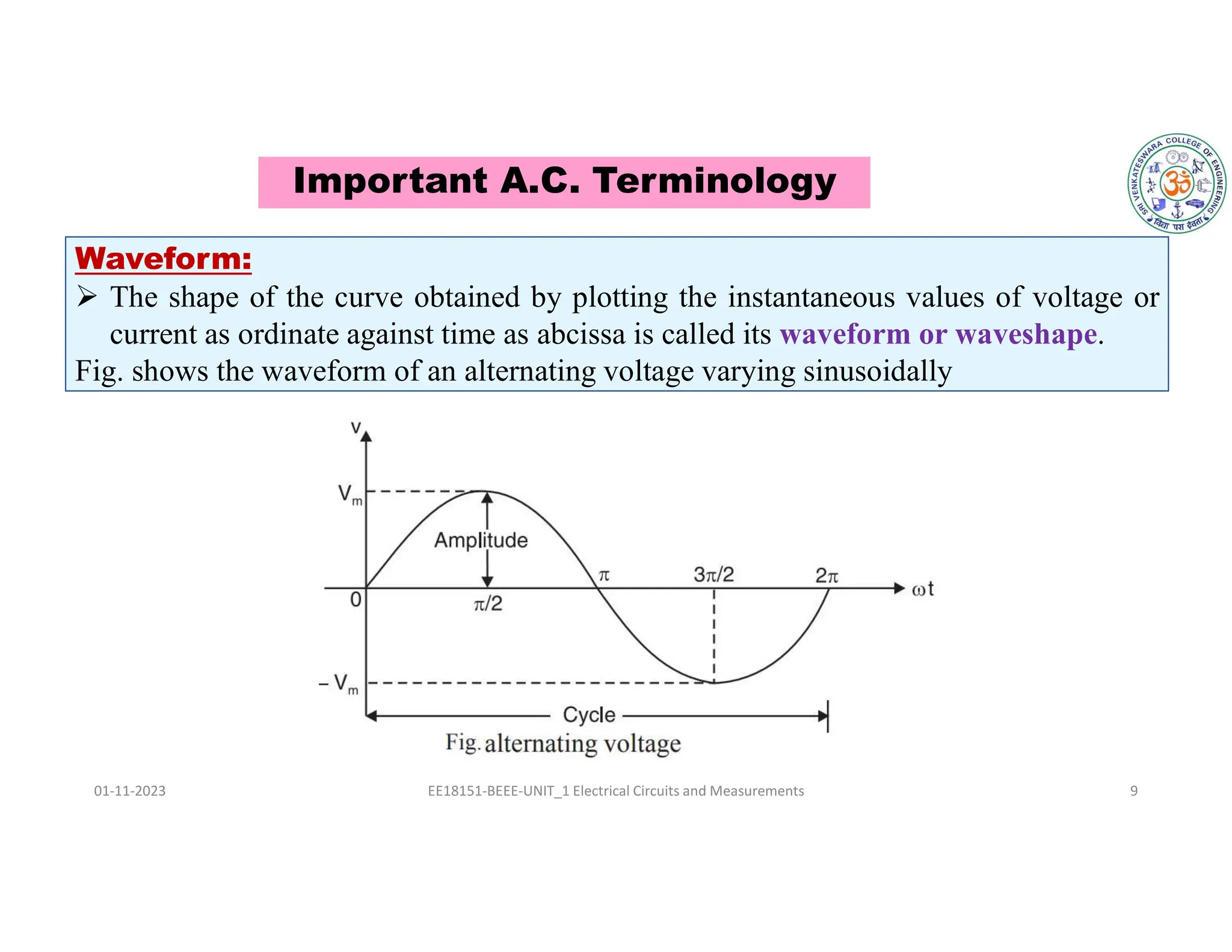
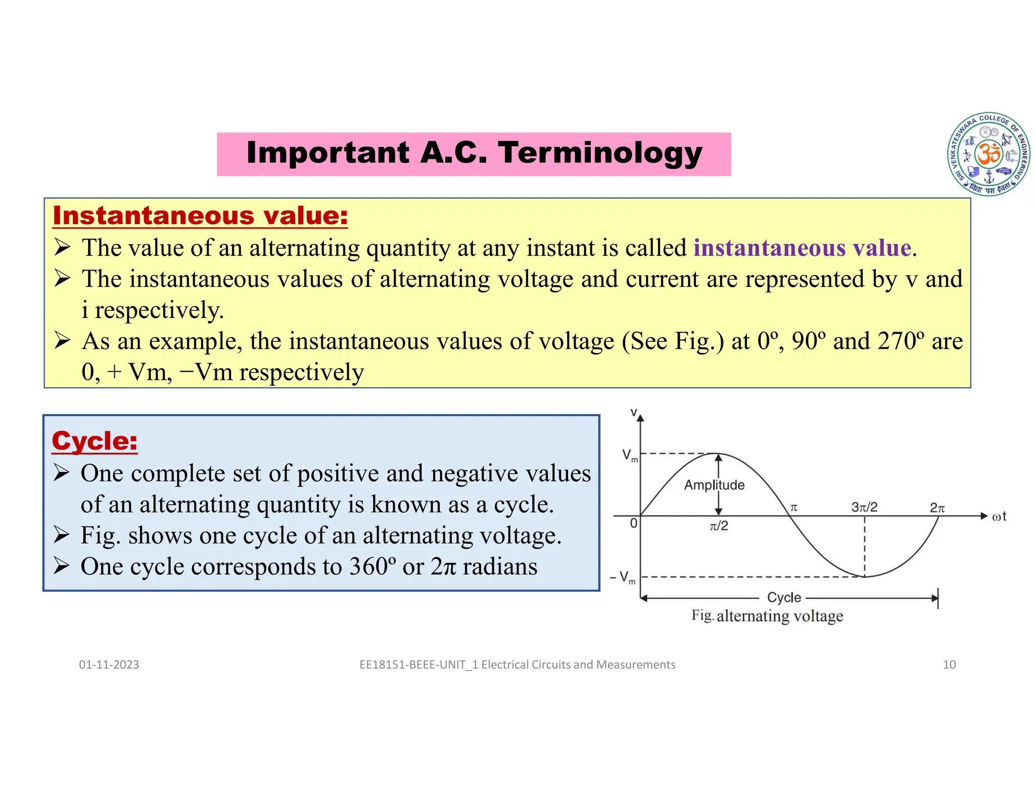
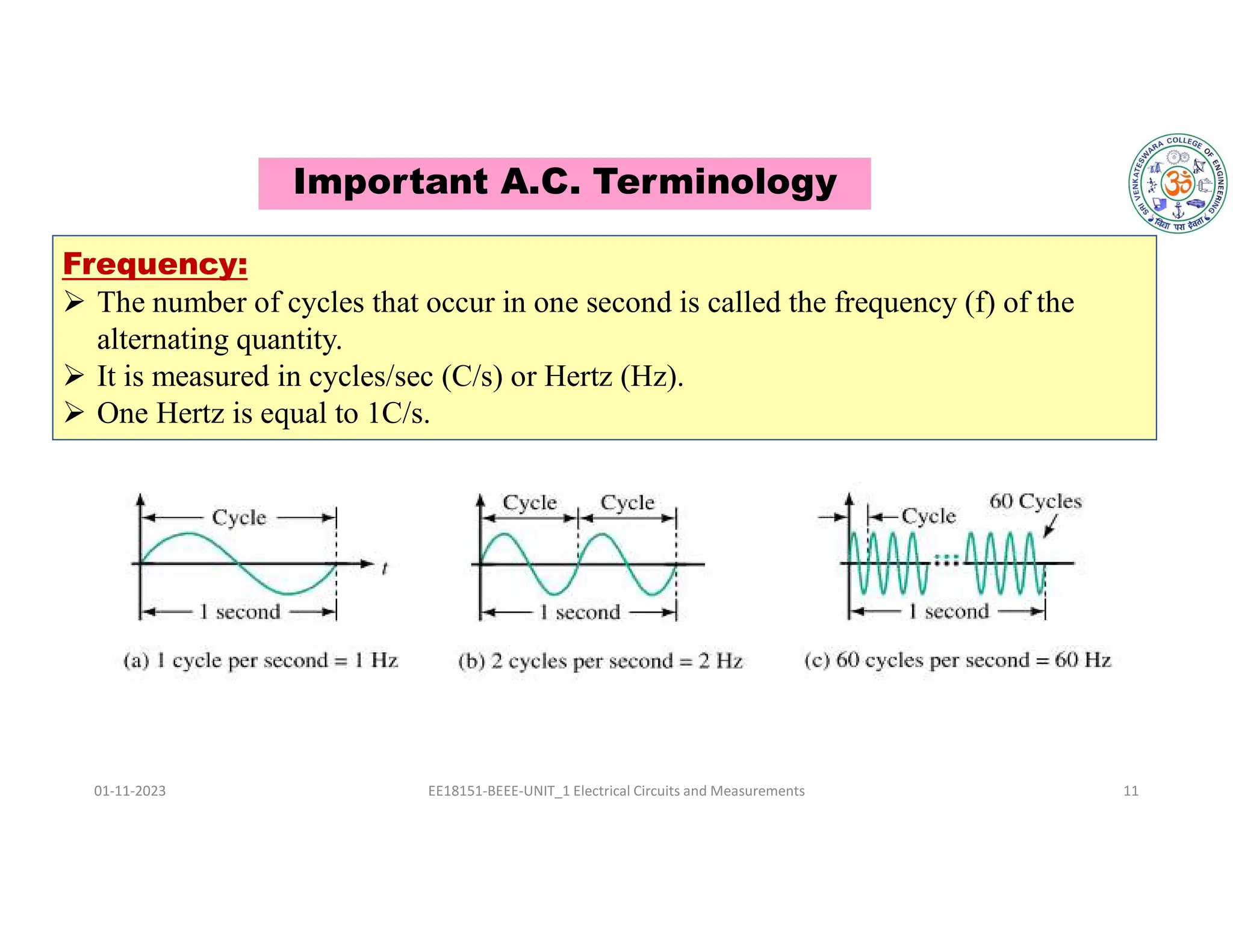
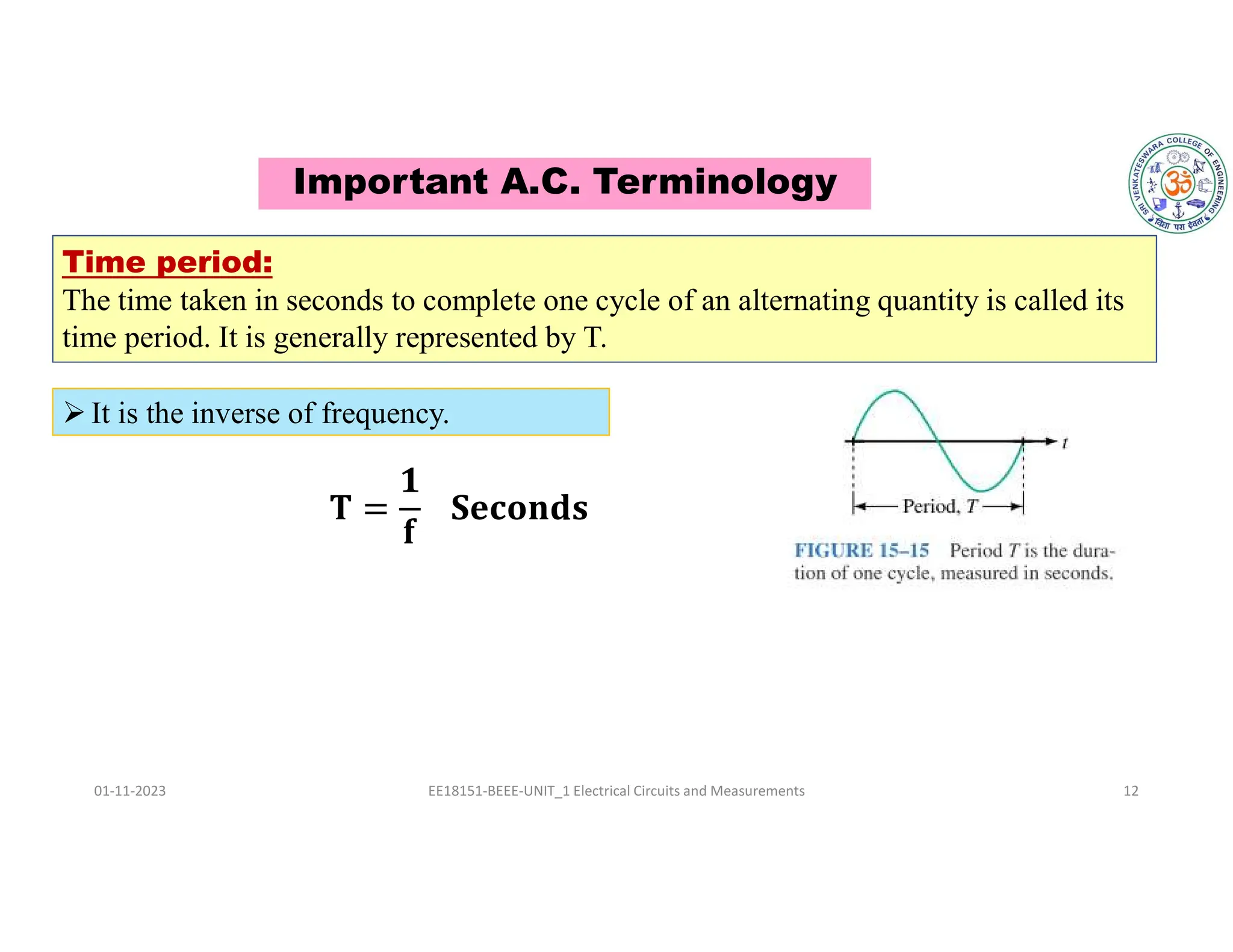
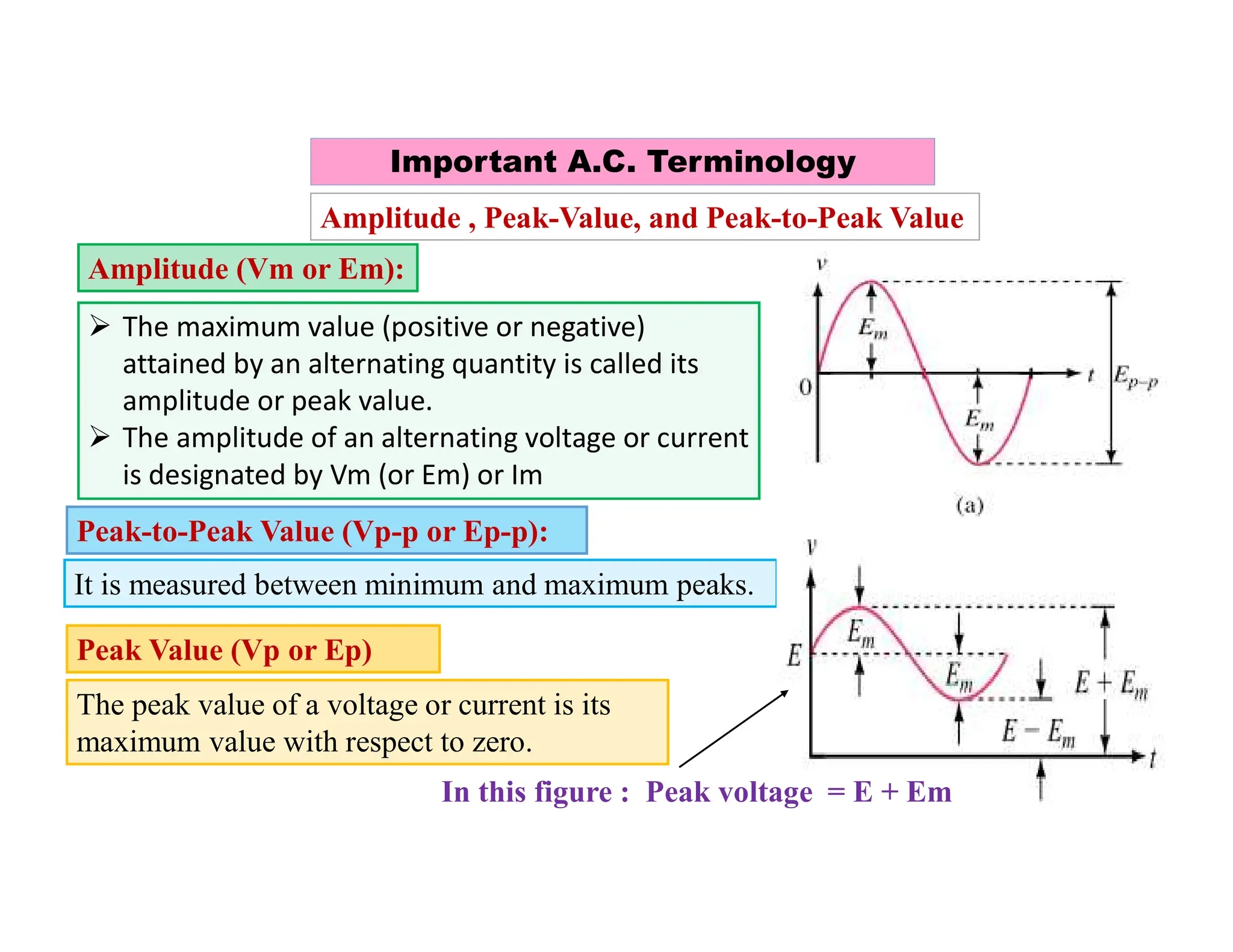
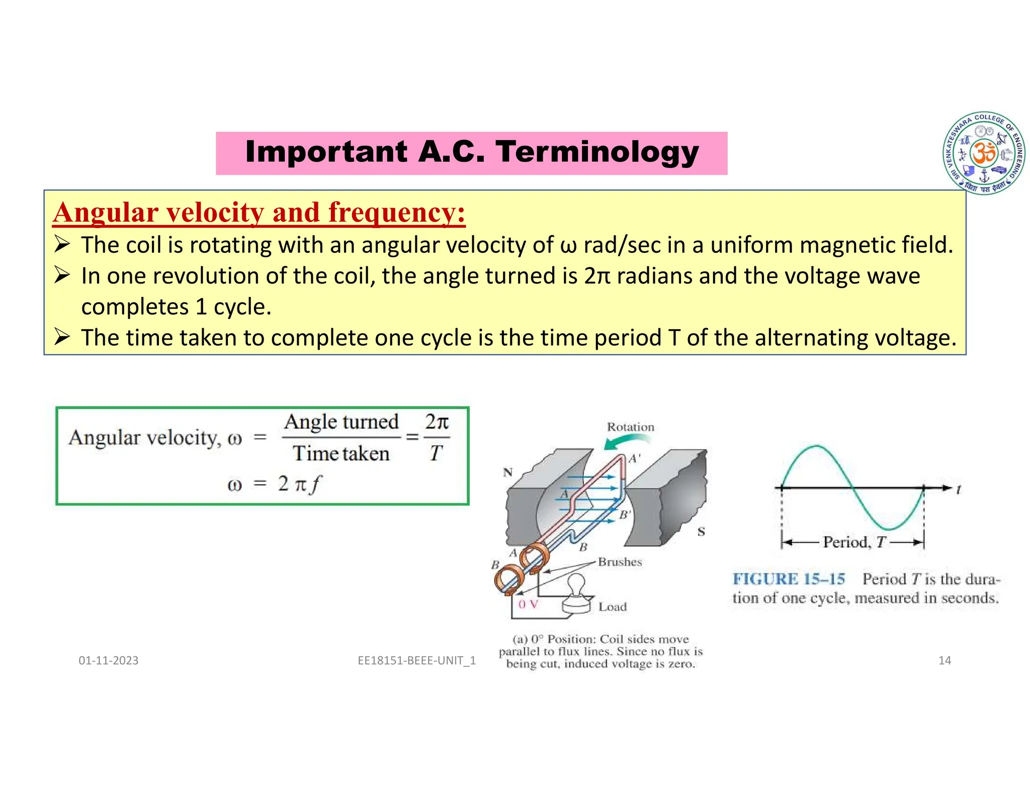
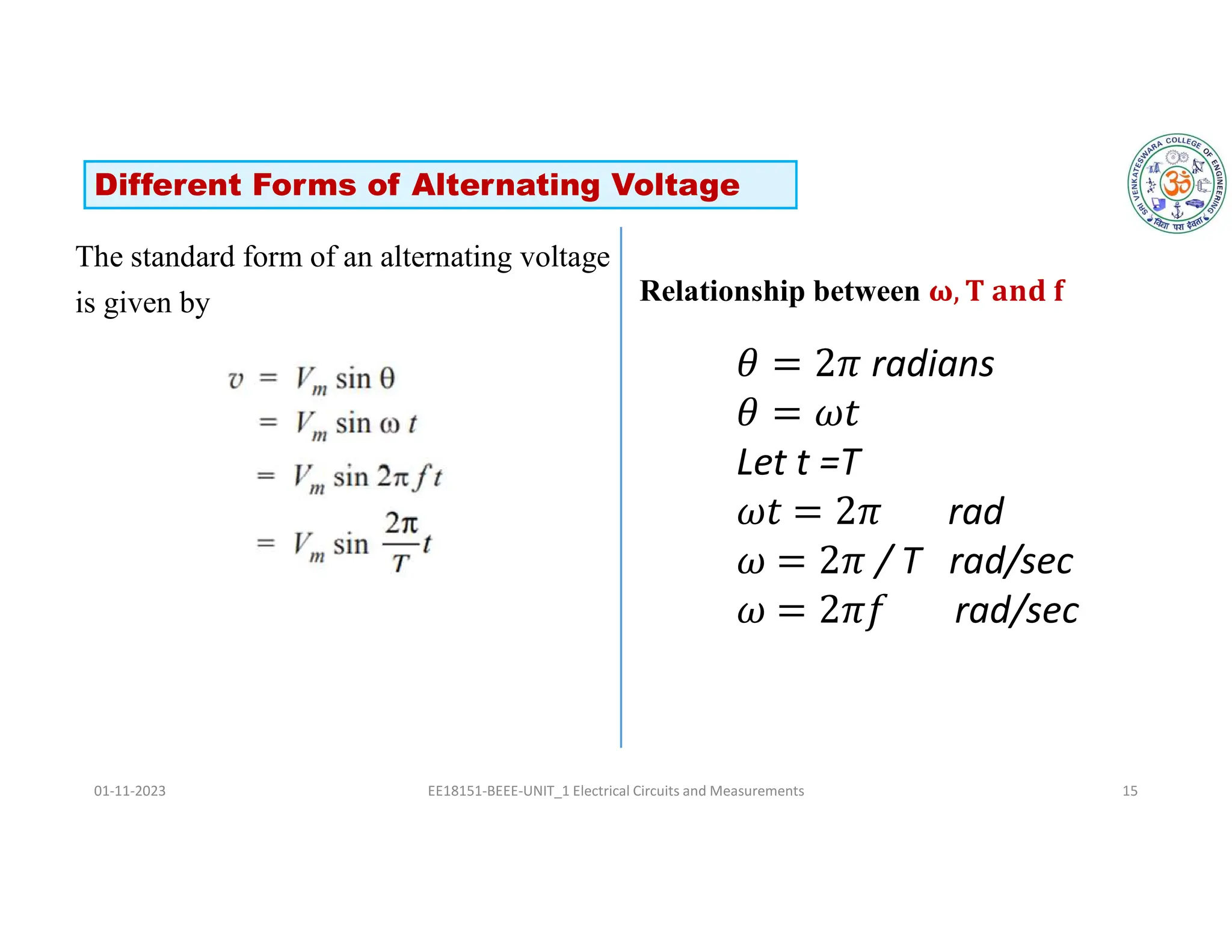
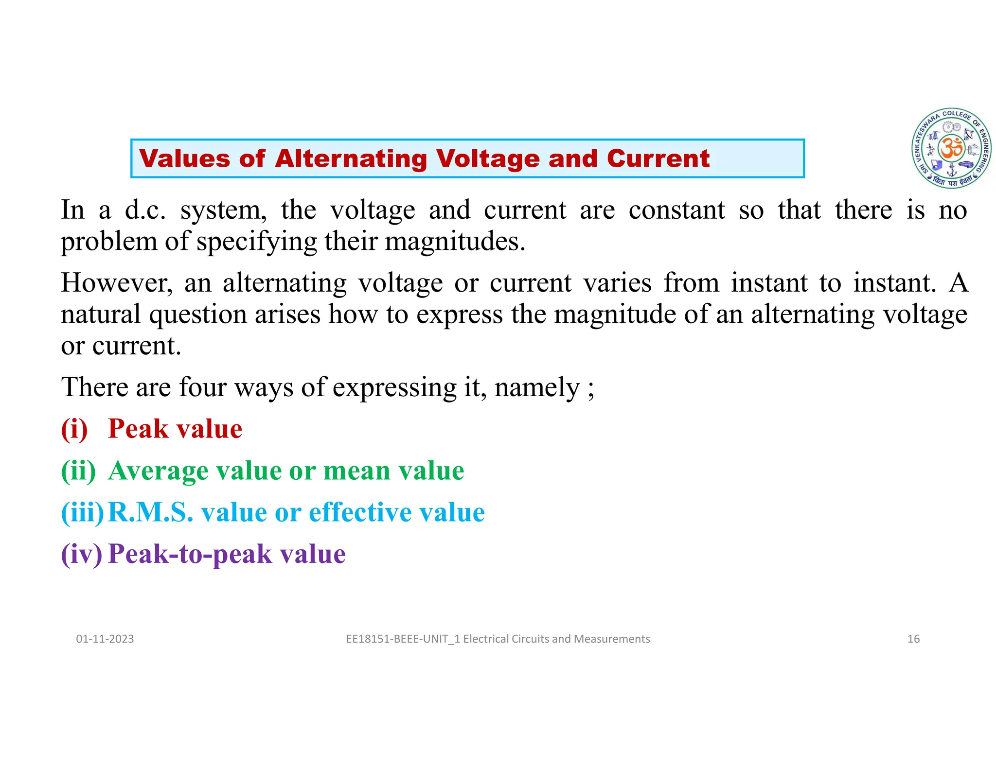
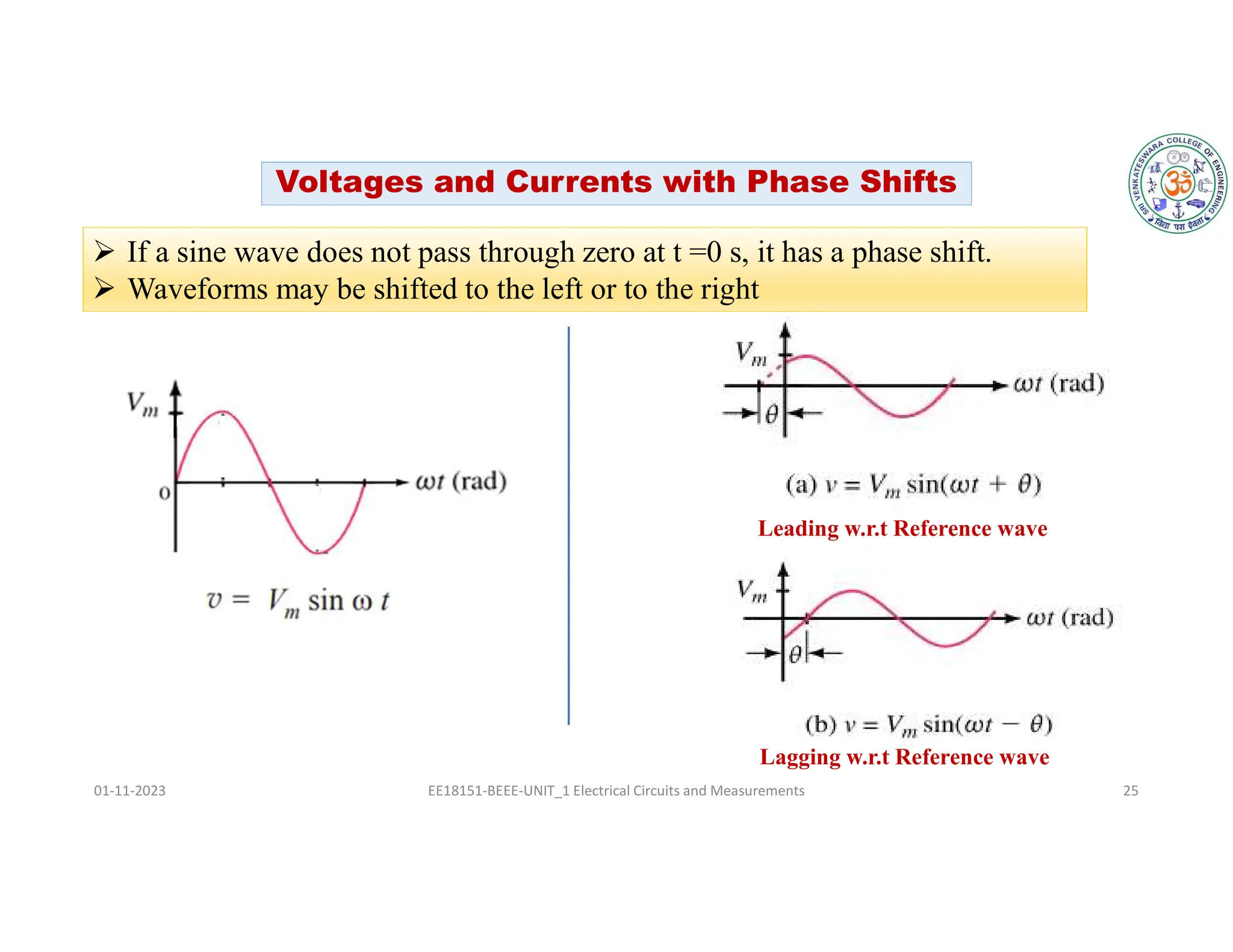
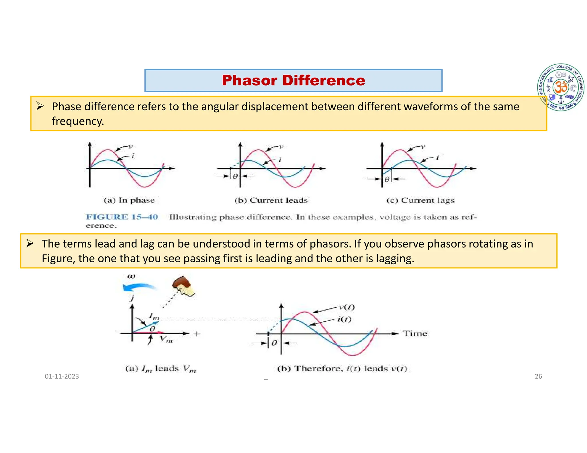
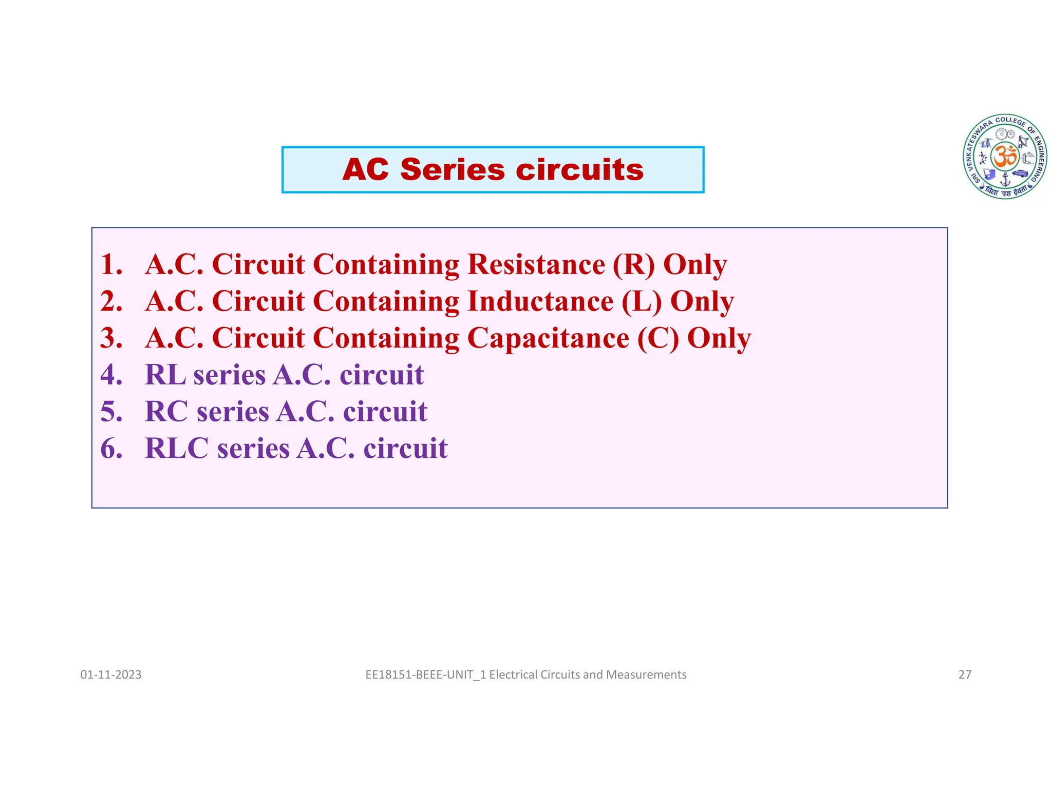
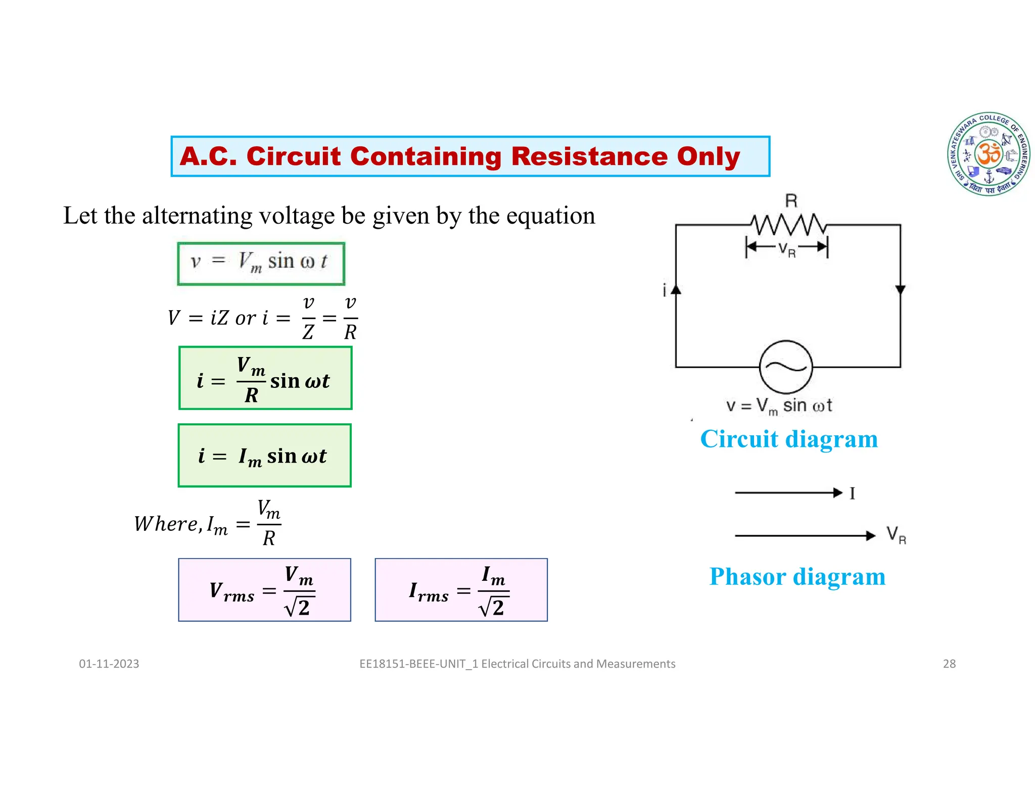
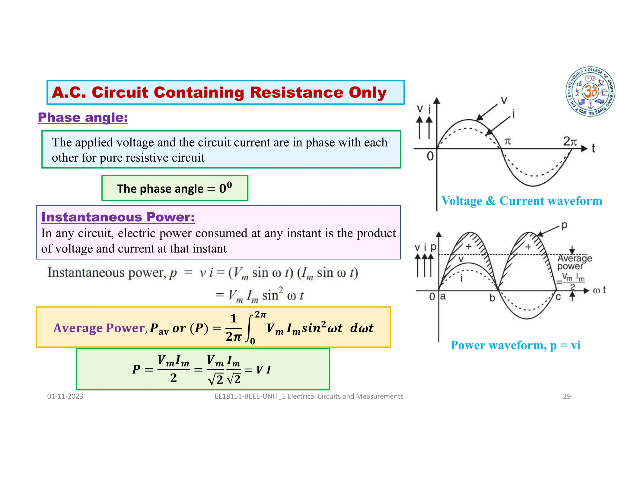
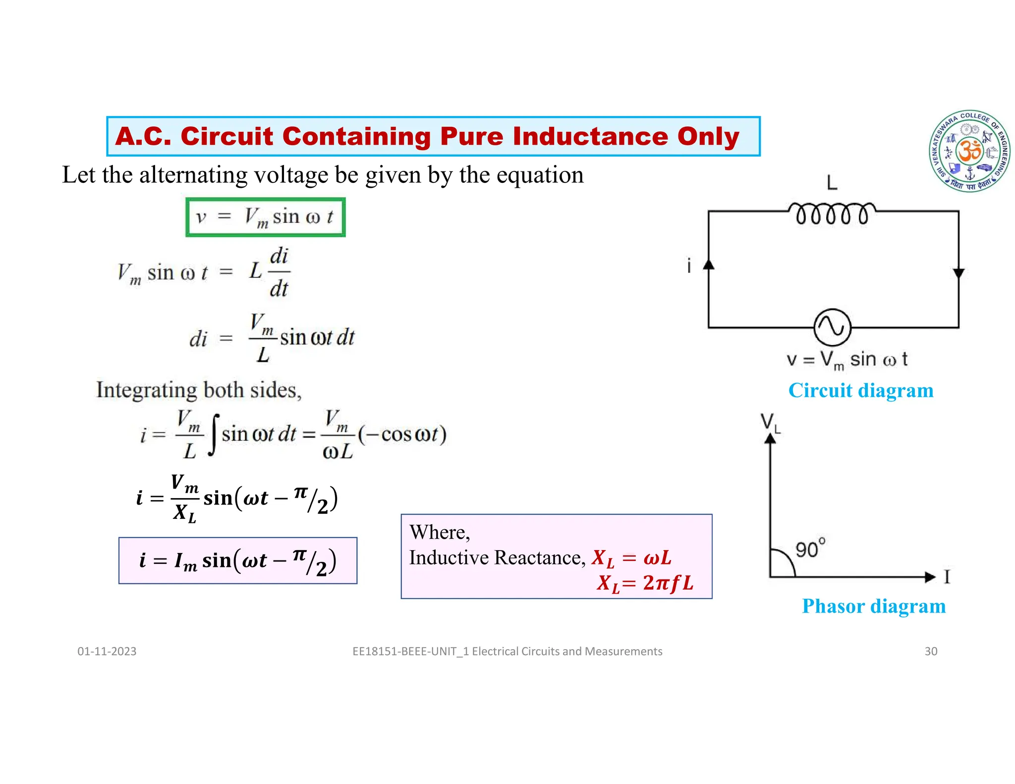
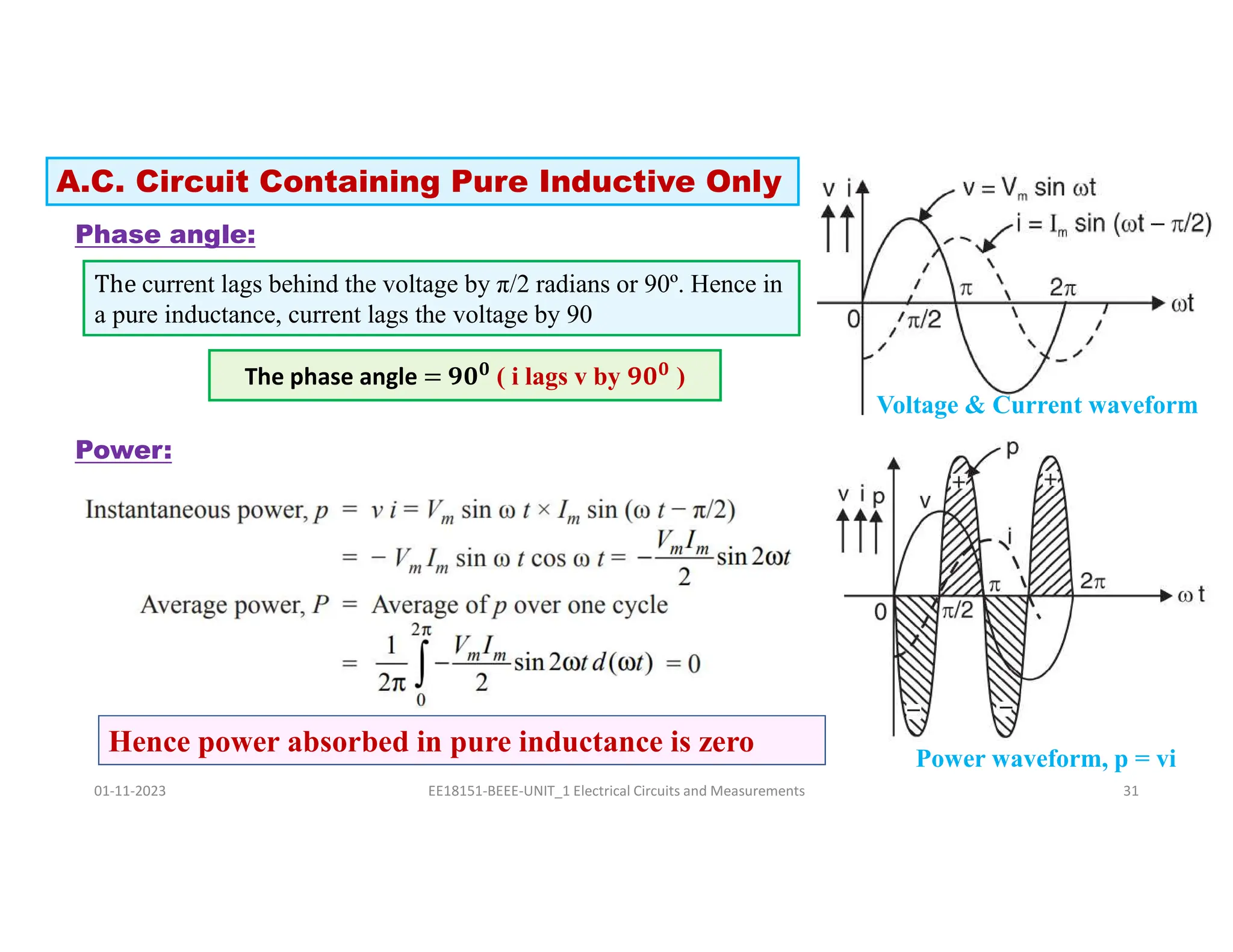
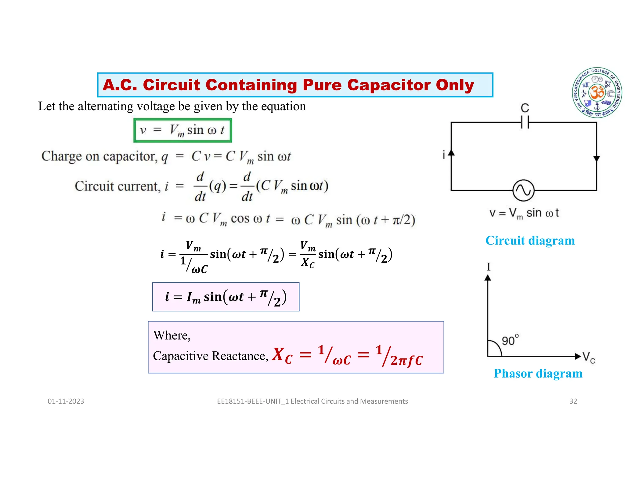
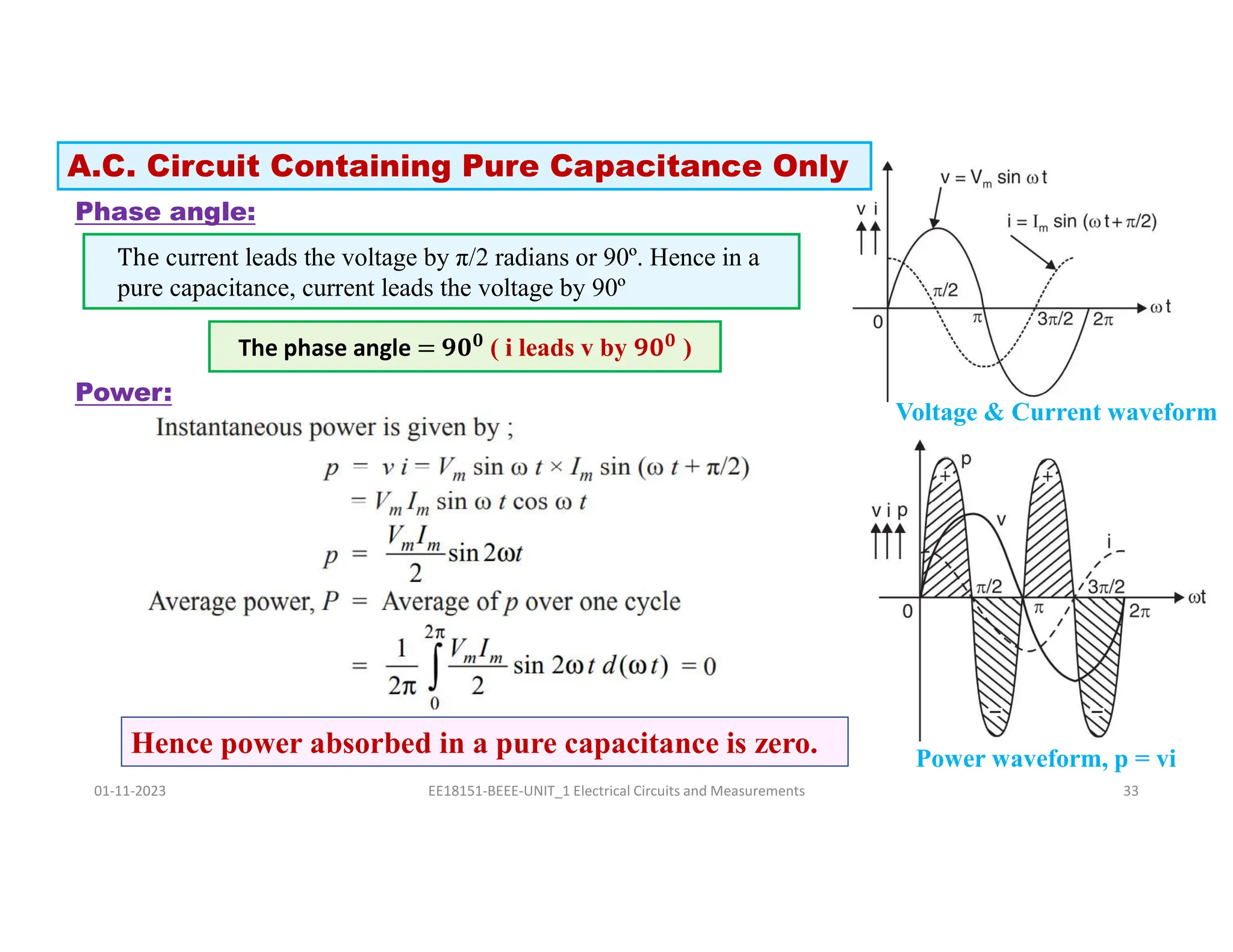
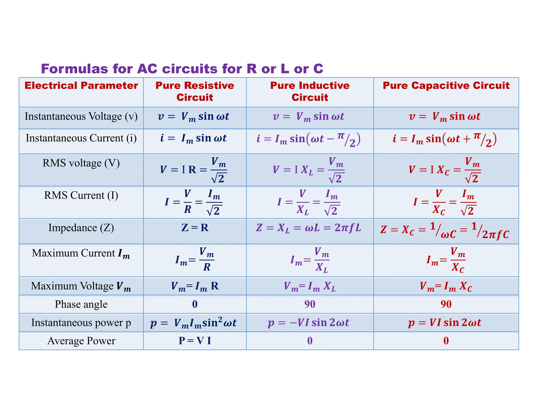
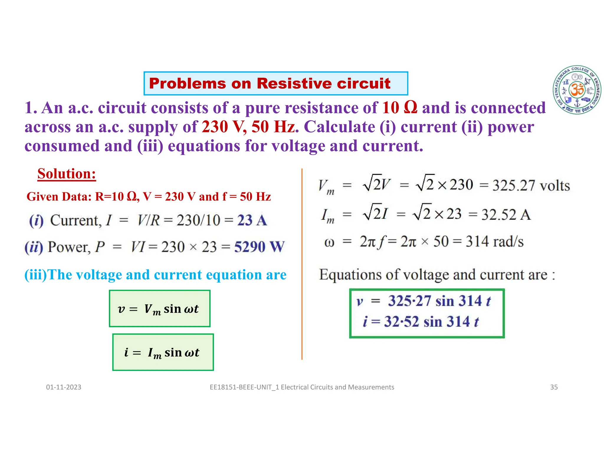
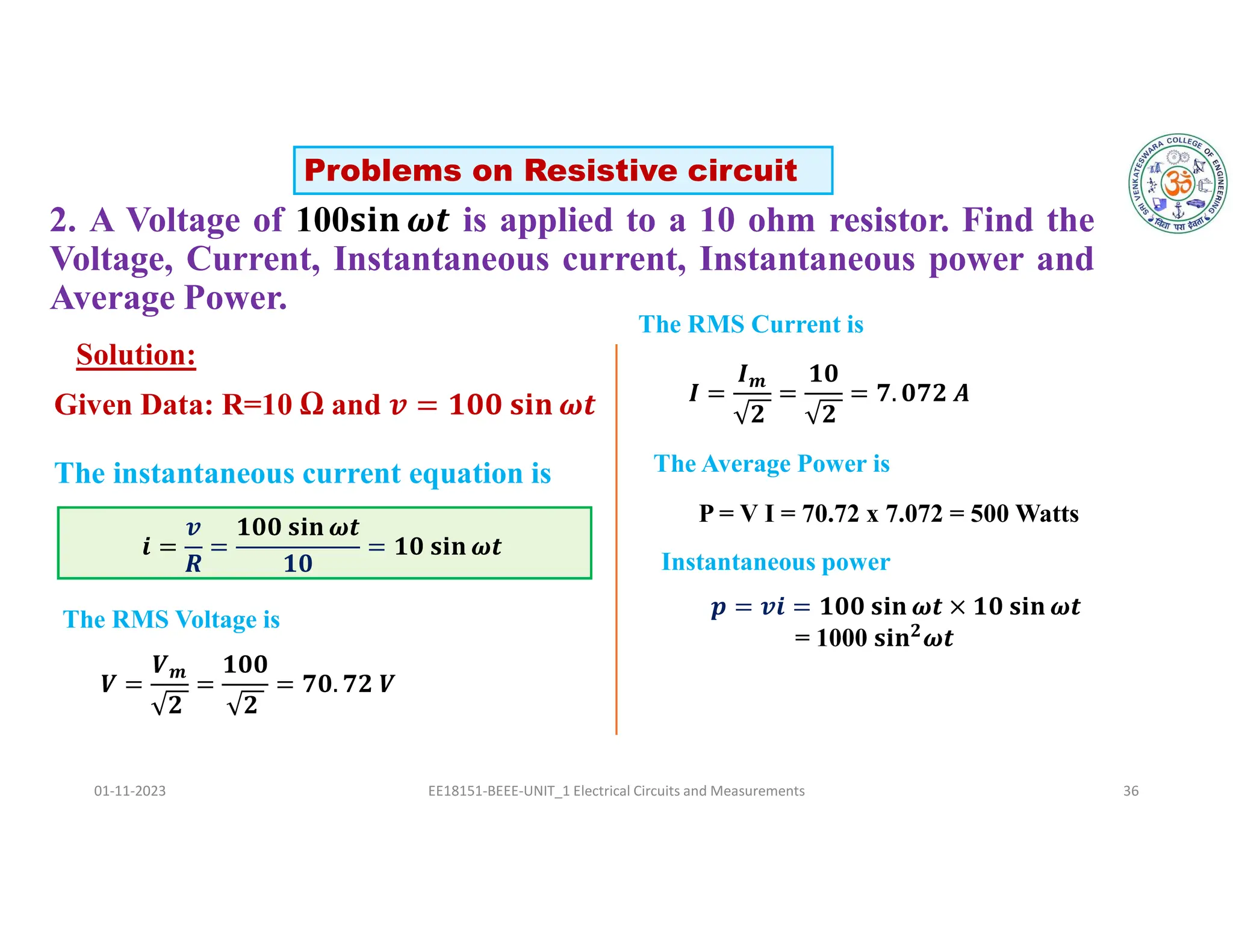
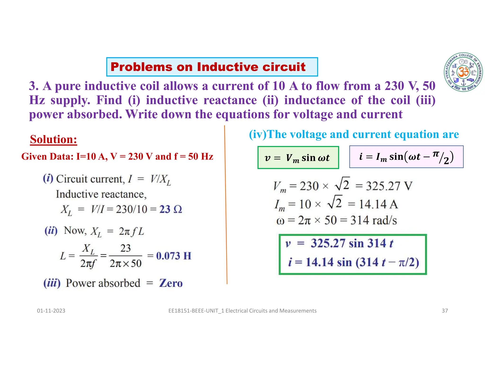
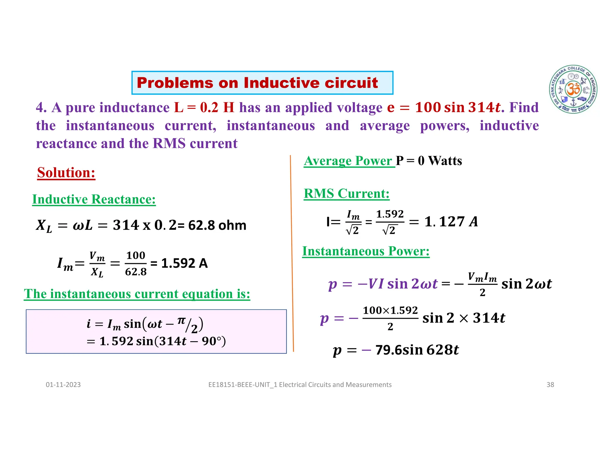
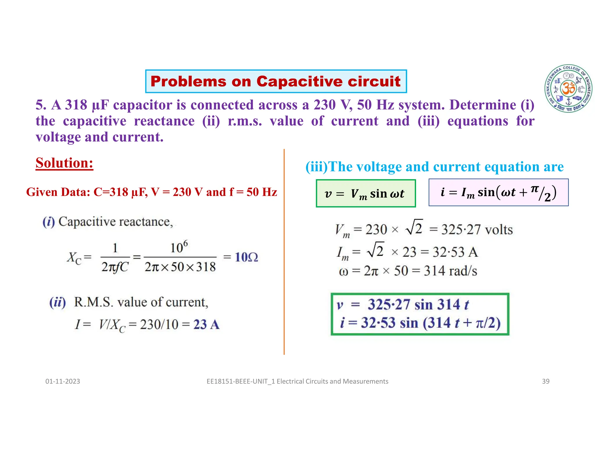
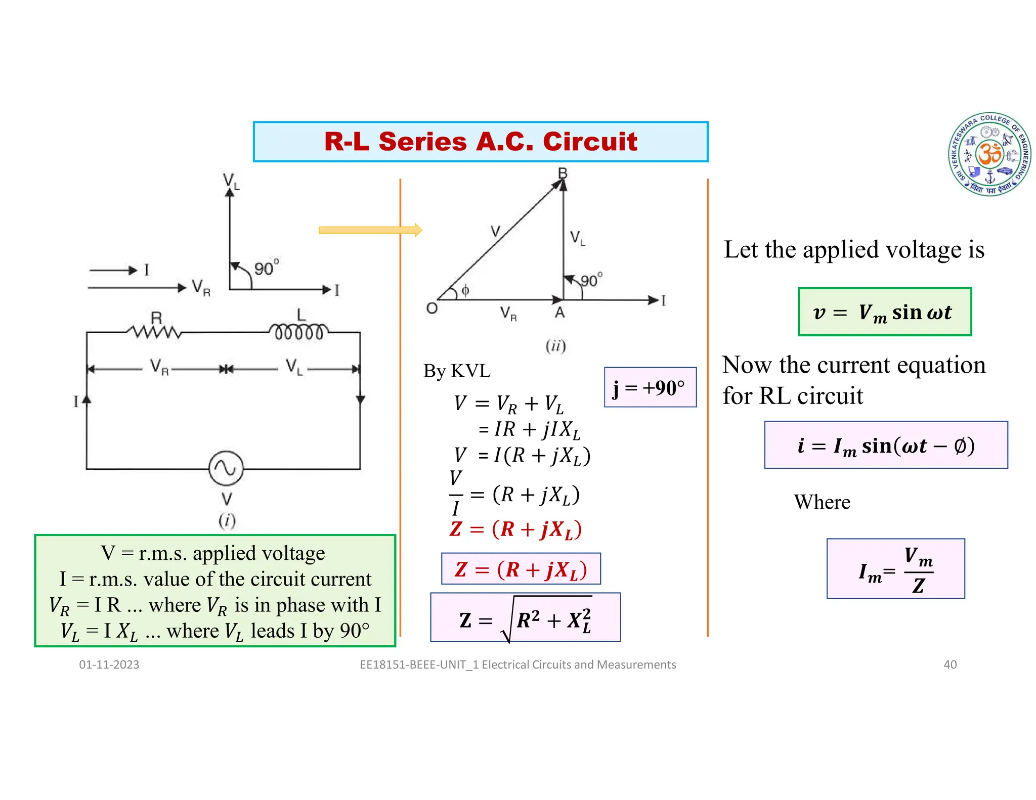
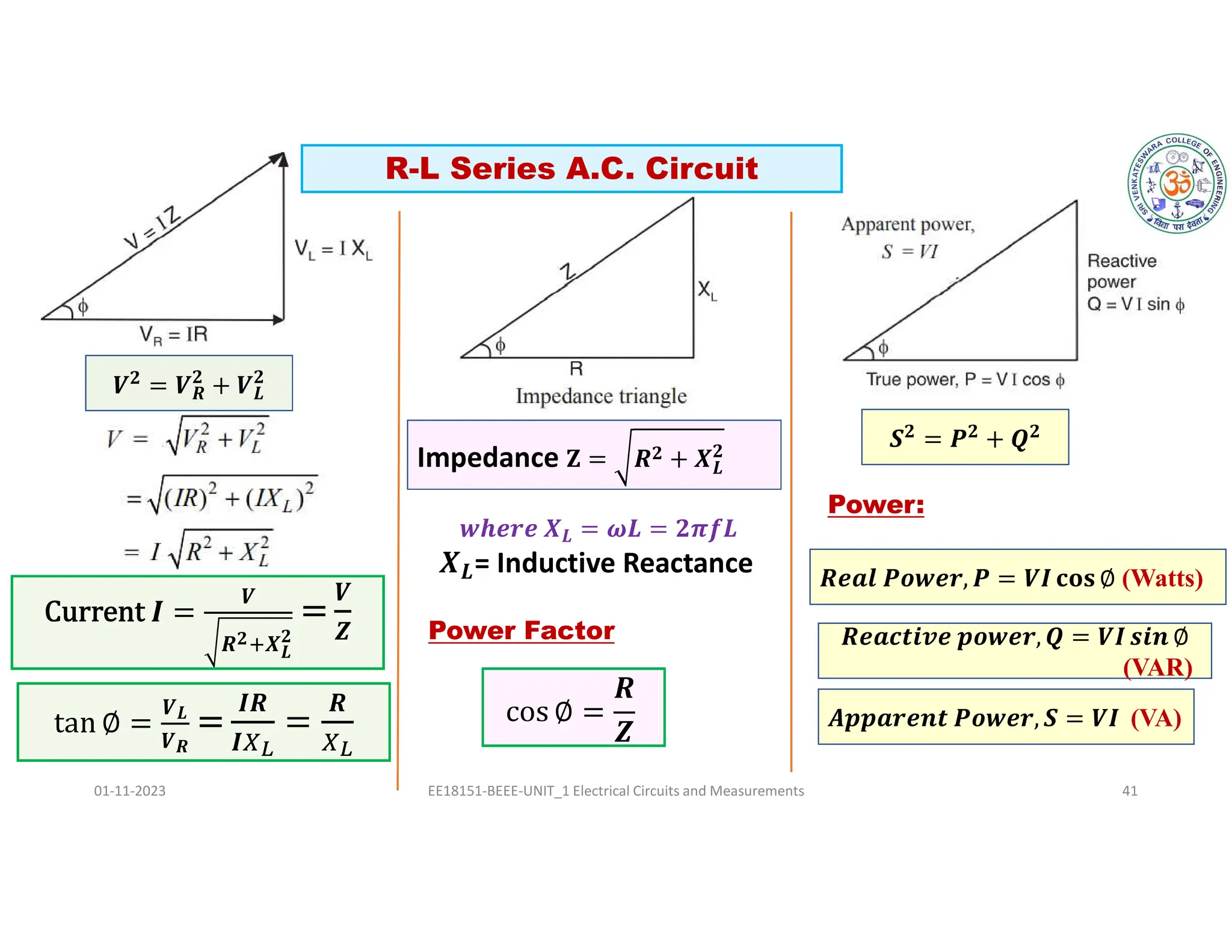
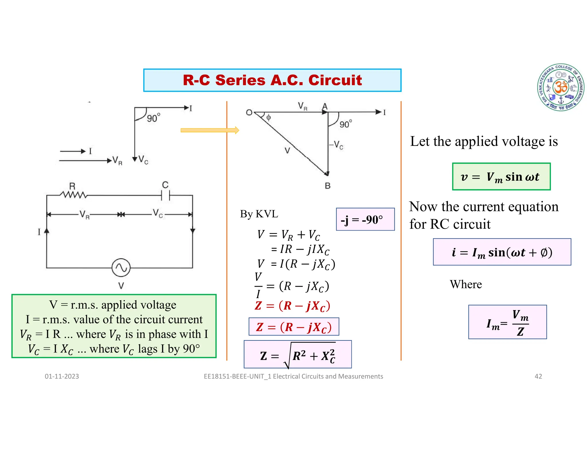
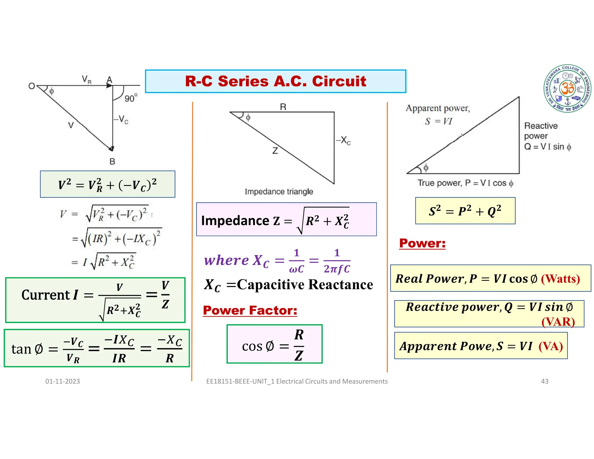
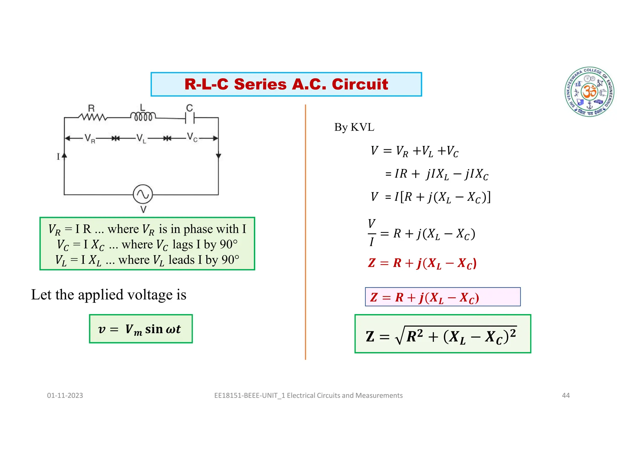
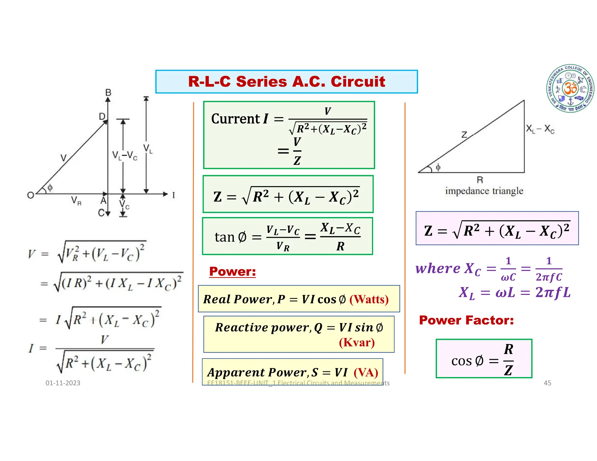
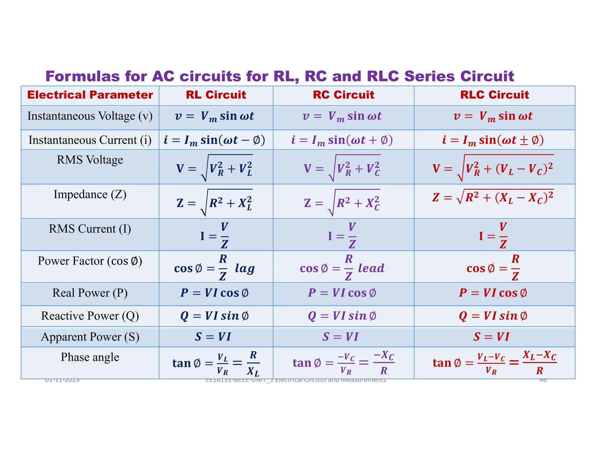
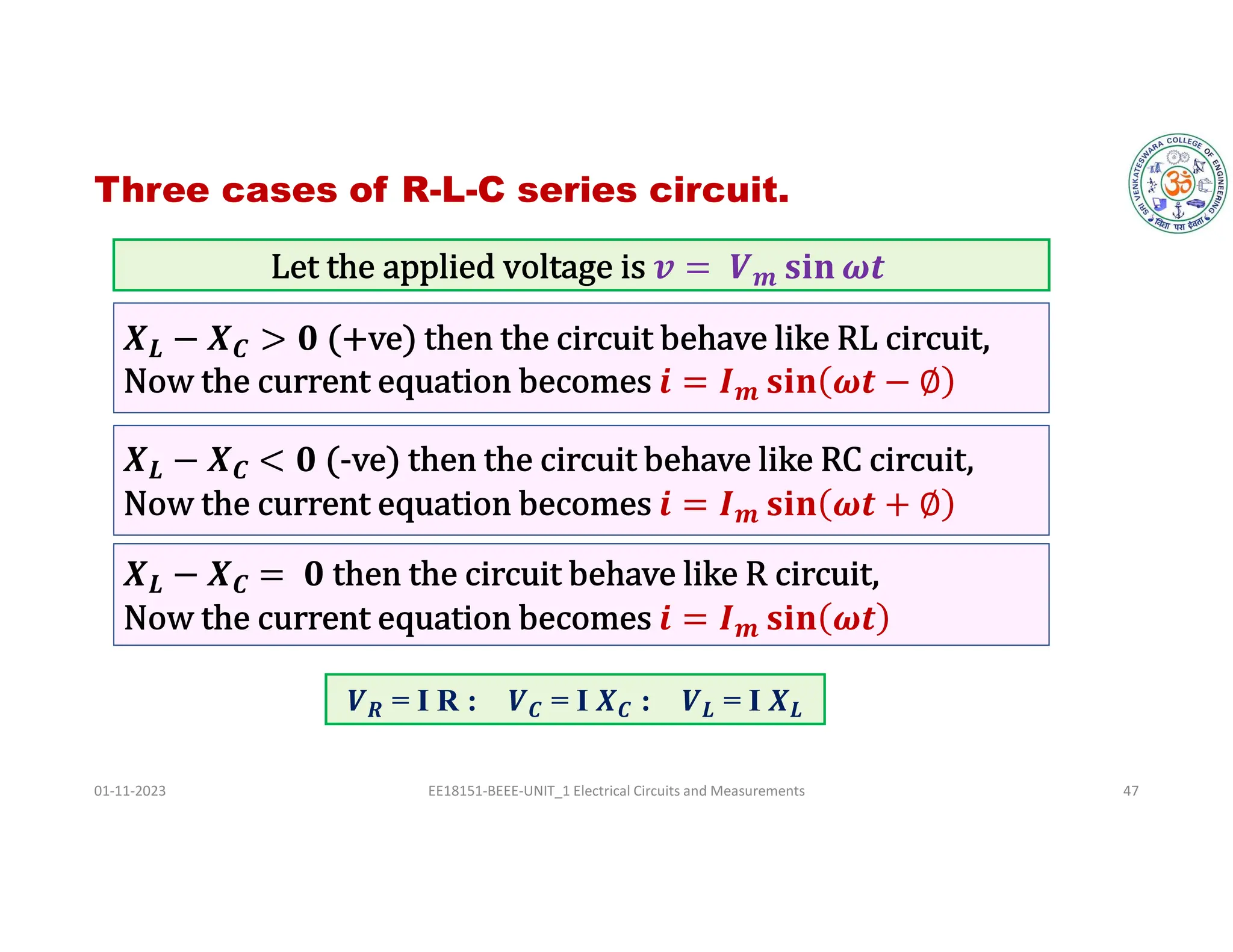
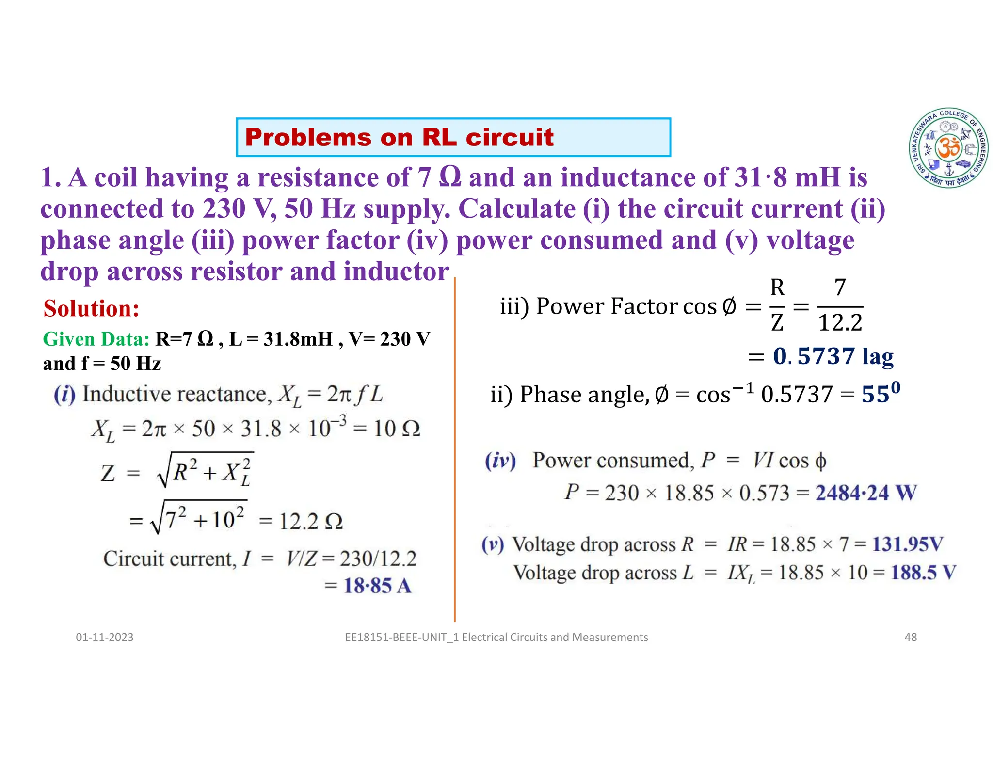
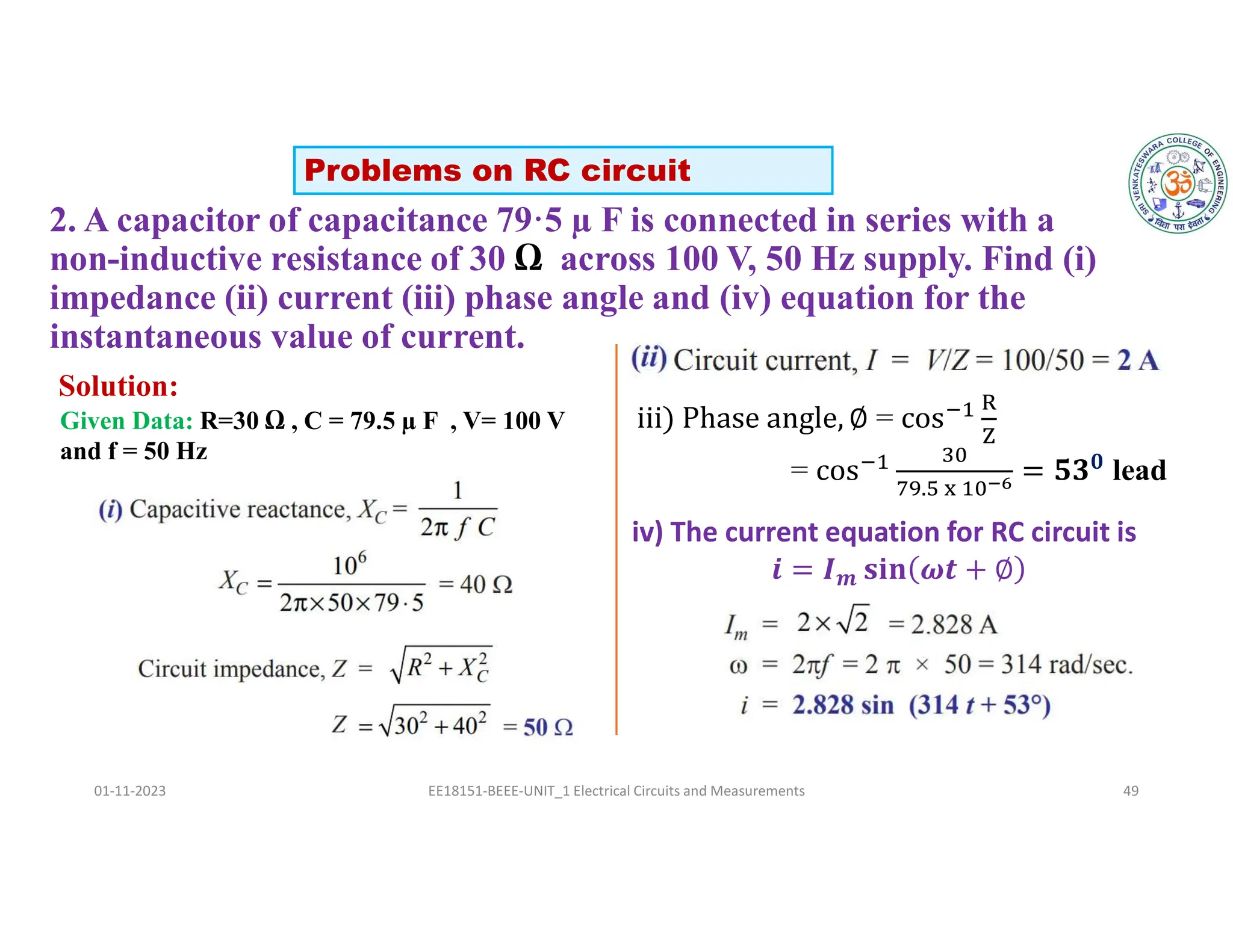
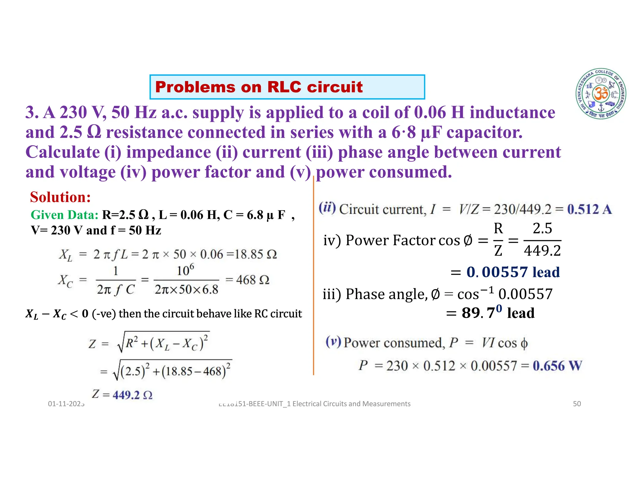
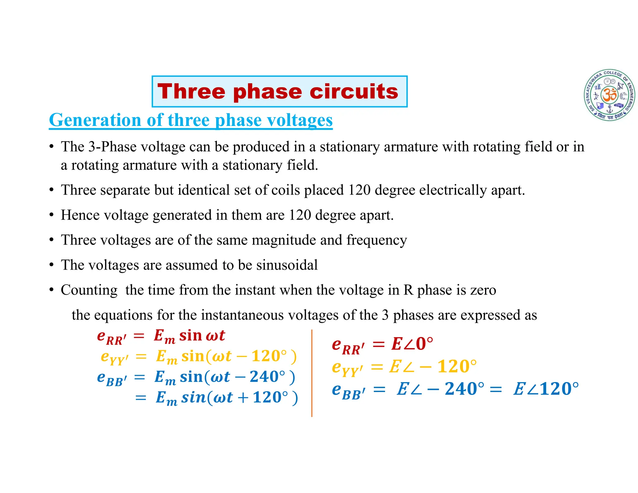
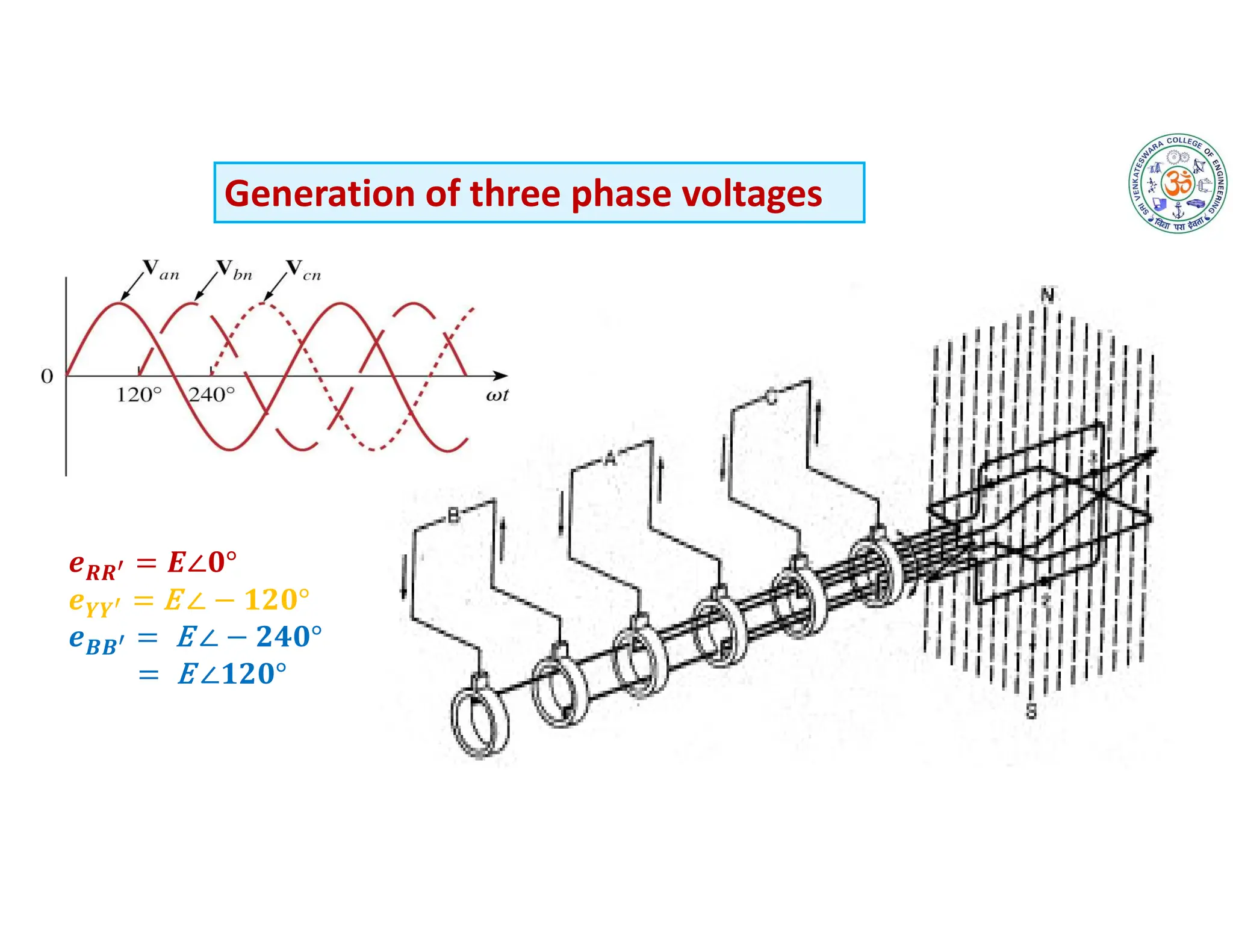
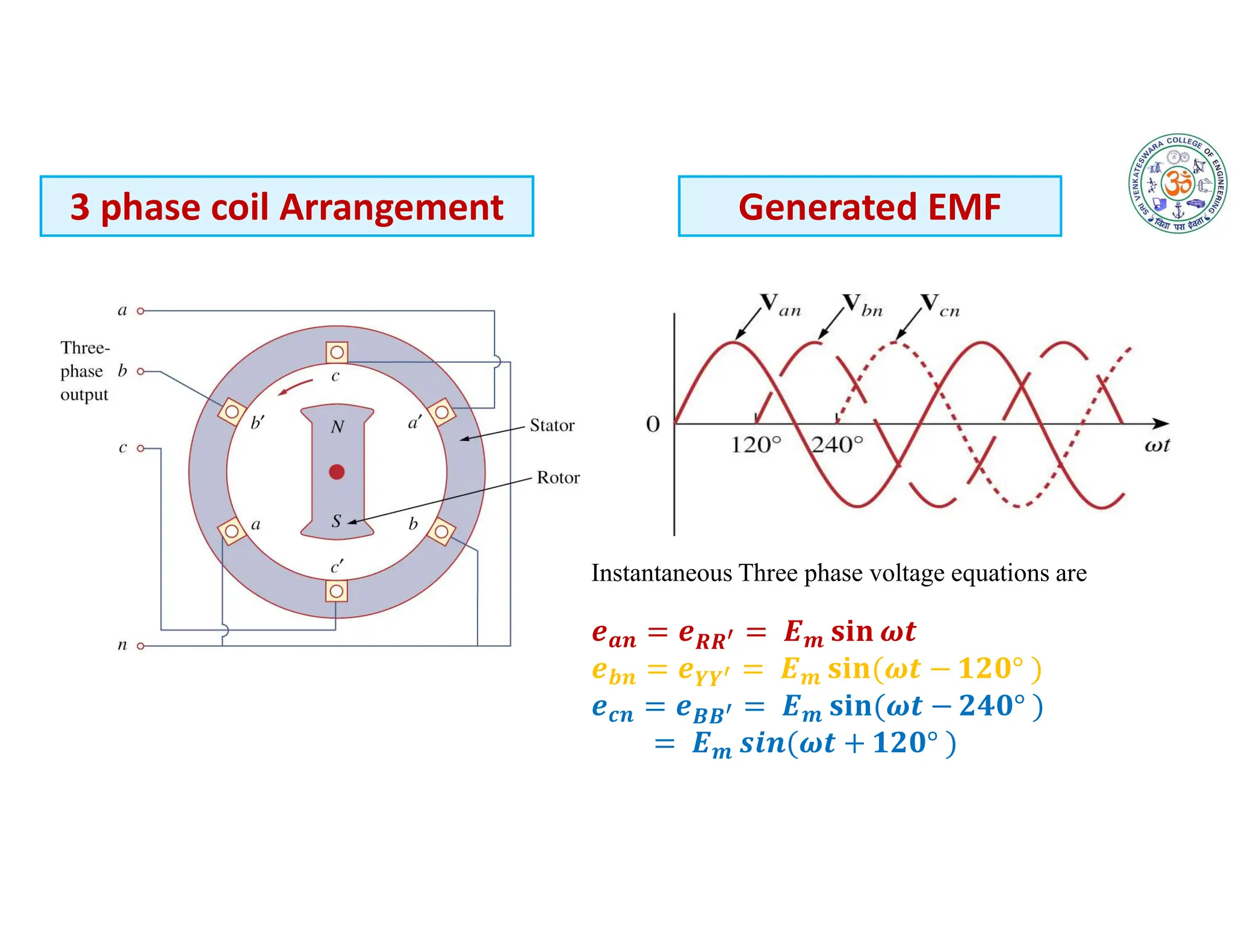
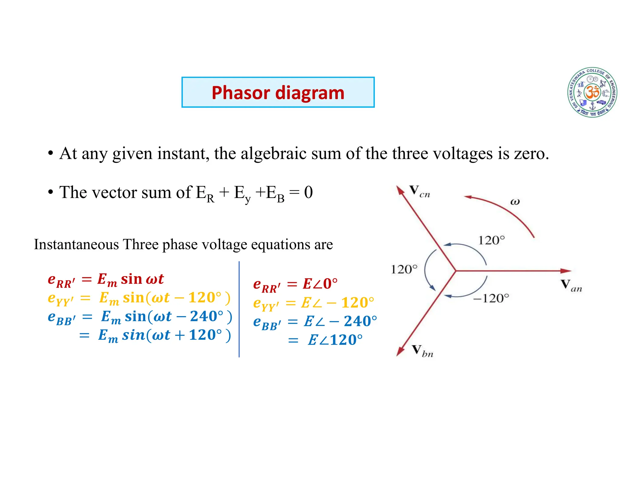
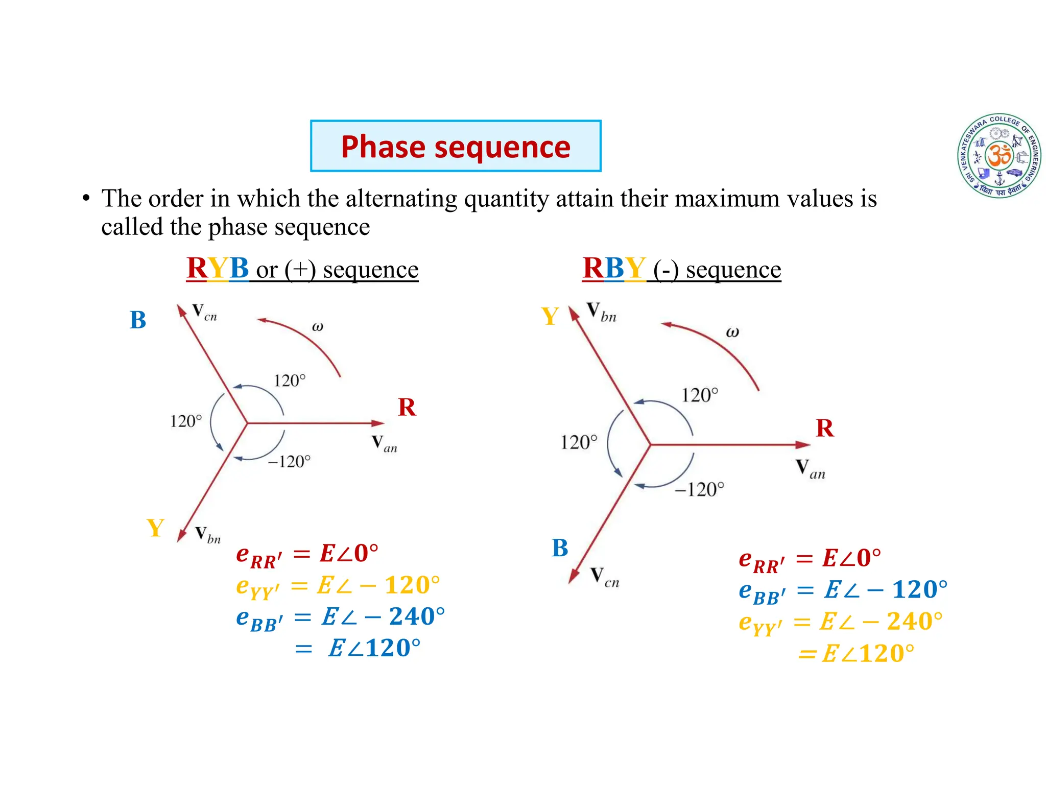
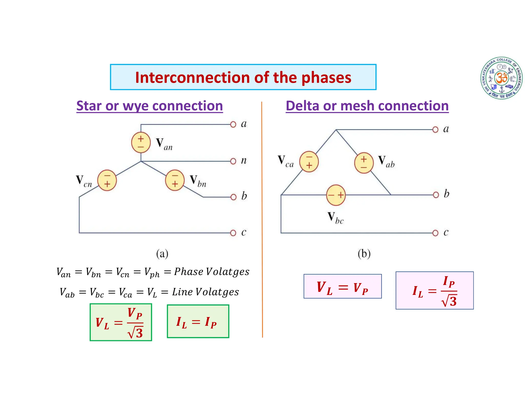
B.TECH โ€“ INFORMATION TECHNOLOGY
EE22151 โ€“ BASIC ELECTRICAL AND ELECTRONICS
ENGINEERING
(UNIT- 1)
ELECTRICAL CIRCUITS
(PART-2: AC CIRCUIT ANALYSIS)
COURSE INSTRUCTOR
THAMIZMANI S
AP/EEE,SVCE
UNIT I
ELECTRICAL CIRCUITS
โ€ข Ohmโ€™s Law โ€“ Kirchhoffโ€™s Laws โ€“ Steady State Solution of DC
Circuits using Mesh Analysis
โ€ข Introduction to AC Circuits โ€“ Waveforms and RMS Value โ€“ Power
and Power factor, Single Phase and Three Phase AC Balanced
Circuits.
01-11-2023 EE18151-BEEE-UNIT_1 Electrical Circuits and Measurements 3
๏ƒ˜ Previously you learned that DC sources have ๏ฌxed polarities and constant
magnitudes and thus produce currents with constant value and unchanging
direction
AC Fundamentals
๏ƒ˜ In contrast, the voltages of ac sources alternate in polarity and vary in
magnitude and thus produce currents that vary in magnitude and alternate in
direction.
๏ƒ˜ Sinusoidal ac Voltage
One complete variation is referred to as a cycle.
Starting at zero,
the voltage increases to a positive peak
amplitude, decreases to zero,
changes polarity,
increases to a negative peak amplitude,
then returns again to zero.
๏ƒ˜Since the waveform repeats itself at regular intervals, it is called a periodic signal.
๏ƒ˜ Symbol for an ac Voltage Source
Lowercase letter e or v is used
to indicate that the voltage varies with time.
AC Fundamentals
๏ƒ˜ During the ๏ฌrst half-cycle,
the source voltage is positive
๏ƒ˜ Therefore, the current is in
the clockwise direction.
๏ƒ˜ During the second half-cycle,
the voltage polarity reverses
๏ƒ˜ Therefore, the current is in the
counterclockwise direction.
๏ƒ˜ Since current is
proportional to
voltage, its shape is
also sinusoidal
A voltage which changes its polarity at regular intervals of time is called an alternating
voltage. When an alternating voltage is applied in a circuit, the current flows first in one
direction and then in the opposite direction; the direction of current at any instant depends
upon the polarity of the voltage.
Alternating Voltage and Current
Generating ac Voltages
๏ƒ˜ One way to generate an ac voltage is to rotate a coil of wire at
constant angular velocity in a ๏ฌxed magnetic ๏ฌeld
๏ƒ˜ The magnitude of the resulting voltage is proportional to the rate at which ๏ฌ‚ux
lines are cut
๏ƒ˜ its polarity is dependent on the direction the coil sides move through the ๏ฌeld.
Generating ac Voltages
Sinusoidal Alternating Voltage and Current
The sinusoidal alternating voltage can be expressed by the equation
A sinusoidal current can be expressed in the same way as voltage
01-11-2023 EE18151-BEEE-UNIT_1 Electrical Circuits and Measurements 8
Important A.C. Terminology
01-11-2023 EE18151-BEEE-UNIT_1 Electrical Circuits and Measurements 9
Waveform:
๏ƒ˜ The shape of the curve obtained by plotting the instantaneous values of voltage or
current as ordinate against time as abcissa is called its waveform or waveshape.
Fig. shows the waveform of an alternating voltage varying sinusoidally
Important A.C. Terminology
01-11-2023 EE18151-BEEE-UNIT_1 Electrical Circuits and Measurements 10
Instantaneous value:
๏ƒ˜ The value of an alternating quantity at any instant is called instantaneous value.
๏ƒ˜ The instantaneous values of alternating voltage and current are represented by v and
i respectively.
๏ƒ˜ As an example, the instantaneous values of voltage (See Fig.) at 0ยบ, 90ยบ and 270ยบ are
0, + Vm, โˆ’Vm respectively
Cycle:
๏ƒ˜ One complete set of positive and negative values
of an alternating quantity is known as a cycle.
๏ƒ˜ Fig. shows one cycle of an alternating voltage.
๏ƒ˜ One cycle corresponds to 360ยบ or 2ฯ€ radians
Important A.C. Terminology
01-11-2023 EE18151-BEEE-UNIT_1 Electrical Circuits and Measurements 11
Frequency:
๏ƒ˜ The number of cycles that occur in one second is called the frequency (f) of the
alternating quantity.
๏ƒ˜ It is measured in cycles/sec (C/s) or Hertz (Hz).
๏ƒ˜ One Hertz is equal to 1C/s.
Important A.C. Terminology
01-11-2023 EE18151-BEEE-UNIT_1 Electrical Circuits and Measurements 12
Time period:
The time taken in seconds to complete one cycle of an alternating quantity is called its
time period. It is generally represented by T.
๏ƒ˜It is the inverse of frequency.
Important A.C. Terminology
Amplitude , Peak-Value, and Peak-to-Peak Value
๏ƒ˜ The maximum value (positive or negative)
attained by an alternating quantity is called its
amplitude or peak value.
๏ƒ˜ The amplitude of an alternating voltage or current
is designated by Vm (or Em) or Im
Amplitude (Vm or Em):
It is measured between minimum and maximum peaks.
Peak-to-Peak Value (Vp-p or Ep-p):
Peak Value (Vp or Ep)
The peak value of a voltage or current is its
maximum value with respect to zero.
In this figure : Peak voltage = E + Em
Important A.C. Terminology
01-11-2023 EE18151-BEEE-UNIT_1 Electrical Circuits and Measurements 14
Angular velocity and frequency:
๏ƒ˜ The coil is rotating with an angular velocity of ฯ‰ rad/sec in a uniform magnetic field.
๏ƒ˜ In one revolution of the coil, the angle turned is 2ฯ€ radians and the voltage wave
completes 1 cycle.
๏ƒ˜ The time taken to complete one cycle is the time period T of the alternating voltage.
The standard form of an alternating voltage
is given by
01-11-2023 EE18151-BEEE-UNIT_1 Electrical Circuits and Measurements 15
Relationship between
radians
Let t =T
rad
/ T rad/sec
rad/sec
Different Forms of Alternating Voltage
In a d.c. system, the voltage and current are constant so that there is no
problem of specifying their magnitudes.
However, an alternating voltage or current varies from instant to instant. A
natural question arises how to express the magnitude of an alternating voltage
or current.
There are four ways of expressing it, namely ;
(i) Peak value
(ii) Average value or mean value
(iii)R.M.S. value or effective value
(iv) Peak-to-peak value
01-11-2023 EE18151-BEEE-UNIT_1 Electrical Circuits and Measurements 16
Values of Alternating Voltage and Current
01-11-2023 EE18151-BEEE-UNIT_1 Electrical Circuits and Measurements 17
๏ƒ˜ It is the maximum value attained by an alternating quantity.
๏ƒ˜ The peak or maximum value of an alternating voltage or current is represented
by Vm or Im.
๏ƒ˜ The knowledge of peak value is important in case of testing materials
Peak Value
01-11-2023 EE18151-BEEE-UNIT_1 Electrical Circuits and Measurements 18
๏ƒ˜ The average value of a waveform is the average of all its values over a
period of time.
๏ƒ˜ In performing such a computation, we regard the area above the time axis
as positive area and area below the time axis as negative area.
๏ƒ˜ The algebraic signs of the areas must be taken into account when
computing the total (net) area.
๏ƒ˜ The time interval over which the net area is computed is the period T of the
waveform.
Average Value
The equation of an alternating current varying sinusoidally is given by
๐š๐ฏ
โˆซ ๐’Š ๐’…๐œฝ
๐…
๐ŸŽ
๐…
โˆซ ๐‘ฐ๐’Ž ๐œฝ ๐’…๐œฝ
๐…
๐ŸŽ
๐…
๐š๐ฏ
๐’Ž
๐ŸŽ
๐…
01-11-2023 EE18151-BEEE-UNIT_1 Electrical Circuits and Measurements 19
๐š๐ฏ
๐Ÿ๐‘ฐ๐’Ž
๐…
= 0.637 ๐’Ž
Average Value, ๐š๐ฏ
๐€๐ซ๐ž๐š ๐จ๐Ÿ ๐จ๐ง๐ž ๐š๐ฅ๐ญ๐ž๐ซ๐š๐ญ๐ข๐จ๐ง
๐›๐š๐ฌ๐ž ๐ฅ๐ž๐ง๐ ๐ญ๐ก ๐จ๐Ÿ ๐จ๐ง๐ž ๐š๐ฅ๐ญ๐ž๐ซ๐š๐ญ๐ข๐จ๐ง
๐š๐ฏ
๐Ÿ๐‘ฝ๐’Ž
๐…
= 0.637 ๐’Ž
Average Value of Sinusoidal Current
Similarly for Voltage
01-11-2023 EE18151-BEEE-UNIT_1 Electrical Circuits and Measurements 20
๏ƒ˜ The effective or r.m.s. value of an alternating current is that steady current (d.c.)
which when flowing through a given resistance for a given time produces the
same amount of heat as produced by the alternating current when flowing through
the same resistance for the same time.
For example, when we say that the r.m.s. or effective value of an alternating current
is 5A, it means that the alternating current will do work (or produce heat) at the same
rate as 5A direct current under similar conditions.
R.M.S. or Effective Value
The r.m.s. value of symmetrical wave can also be expressed as :
The r.m.s. or effective value of an alternating voltage can similarly be
expressed as :
01-11-2023 EE18151-BEEE-UNIT_1 Electrical Circuits and Measurements 21
R.M.S. or Effective Value
The equation of an alternating current varying sinusoidally is given by
๐’“๐’Ž๐’”
โˆซ ๐’Š๐Ÿ ๐’…๐œฝ
๐…
๐ŸŽ
๐…
โˆซ ๐‘ฐ๐’Ž
๐Ÿ ๐’”๐’Š๐’๐Ÿ๐œฝ ๐’…๐œฝ
๐…
๐ŸŽ
๐…
๐’“๐’Ž๐’”
๐‘ฐ๐’Ž
๐…
๐Ÿ ๐Ÿ๐œฝ
๐Ÿ
๐…
๐ŸŽ
=
๐‘ฐ๐’Ž
๐Ÿ ๐…
๐œฝ
๐Ÿ ๐ŸŽ
๐…
=
๐‘ฐ๐’Ž
๐Ÿ ๐…
01-11-2023 EE18151-BEEE-UNIT_1 Electrical Circuits and Measurements 22
๐’“๐’Ž๐’”
๐‘ฐ๐’Ž
๐Ÿ
= 0.707 ๐’Ž
R.M.S value, ๐’“๐’Ž๐’”
๐€๐ซ๐ž๐š ๐จ๐Ÿ ๐ก๐š๐ฅ๐Ÿ ๐œ๐ฒ๐œ๐ฅ๐ž ๐จ๐Ÿ ๐ฌ๐ช๐ฎ๐š๐ซ๐ž ๐ฐ๐š๐ฏ๐ž
๐ก๐š๐ฅ๐Ÿ ๐œ๐ฒ๐œ๐ฅ๐ž ๐›๐š๐ฌ๐ž
๐’“๐’Ž๐’”
๐‘ฝ๐’Ž
๐Ÿ
= 0.707 ๐’Ž
R.M.S. Value of Sinusoidal Current
Similarly for Voltage
01-11-2023 EE18151-BEEE-UNIT_1 Electrical Circuits and Measurements 23
Form factor:
๏ƒ˜ The ratio of r.m.s. value to the average value of an alternating quantity is known as
form factor
Form Factor and Peak Factor
01-11-2023 EE18151-BEEE-UNIT_1 Electrical Circuits and Measurements 24
Peak factor:
๏ƒ˜ The ratio of maximum value to the r.m.s. value of an alternating quantity is known
as peak factor
๏ƒ˜ Peak factor is also called crest factor or amplitude factor.
Form Factor and Peak Factor
01-11-2023 EE18151-BEEE-UNIT_1 Electrical Circuits and Measurements 25
Voltages and Currents with Phase Shifts
Leading w.r.t Reference wave
๏ƒ˜ If a sine wave does not pass through zero at t =0 s, it has a phase shift.
๏ƒ˜ Waveforms may be shifted to the left or to the right
Lagging w.r.t Reference wave
01-11-2023 EE18151-BEEE-UNIT_1 Electrical Circuits and Measurements 26
Phasor Difference
๏ƒ˜ Phase difference refers to the angular displacement between different waveforms of the same
frequency.
๏ƒ˜ The terms lead and lag can be understood in terms of phasors. If you observe phasors rotating as in
Figure, the one that you see passing first is leading and the other is lagging.
01-11-2023 EE18151-BEEE-UNIT_1 Electrical Circuits and Measurements 27
AC Series circuits
1. A.C. Circuit Containing Resistance (R) Only
2. A.C. Circuit Containing Inductance (L) Only
3. A.C. Circuit Containing Capacitance (C) Only
4. RL series A.C. circuit
5. RC series A.C. circuit
6. RLC series A.C. circuit
Let the alternating voltage be given by the equation
๐‘Šโ„Ž๐‘’๐‘Ÿ๐‘’, ๐ผ =
๐‘‰
๐‘…
01-11-2023 EE18151-BEEE-UNIT_1 Electrical Circuits and Measurements 28
Circuit diagram
Phasor diagram
๐‘‰ = ๐‘–๐‘ ๐‘œ๐‘Ÿ ๐‘– =
๐‘ฃ
๐‘
=
๐‘ฃ
๐‘…
๐’Š =
๐‘ฝ๐’Ž
๐‘น
๐ฌ๐ข๐ง ๐Ž๐’•
๐’Š = ๐‘ฐ๐’Ž ๐ฌ๐ข๐ง ๐Ž๐’•
๐‘ฝ๐’“๐’Ž๐’” =
๐‘ฝ๐’Ž
๐Ÿ
๐‘ฐ๐’“๐’Ž๐’” =
๐‘ฐ๐’Ž
๐Ÿ
A.C. Circuit Containing Resistance Only
Phase angle:
01-11-2023 EE18151-BEEE-UNIT_1 Electrical Circuits and Measurements 29
The phase angle = ๐ŸŽ๐ŸŽ
Instantaneous Power:
In any circuit, electric power consumed at any instant is the product
of voltage and current at that instant
The applied voltage and the circuit current are in phase with each
other for pure resistive circuit
Voltage & Current waveform
Power waveform, p = vi
๐€๐ฏ๐ž๐ซ๐š๐ ๐ž ๐๐จ๐ฐ๐ž๐ซ, ๐‘ท๐š๐ฏ ๐’๐’“ (๐‘ท) =
๐Ÿ
๐Ÿ๐…
๐‘ฝ๐’Ž ๐‘ฐ๐’Ž๐’”๐’Š๐’๐Ÿ
๐Ž๐’• ๐’…๐Ž๐’•
๐Ÿ๐…
๐ŸŽ
๐‘ท =
๐‘ฝ๐’Ž๐‘ฐ๐’Ž
๐Ÿ
=
๐‘ฝ๐’Ž
๐Ÿ
๐‘ฐ๐’Ž
๐Ÿ
= ๐‘ฝ ๐‘ฐ
A.C. Circuit Containing Resistance Only
Let the alternating voltage be given by the equation
01-11-2023 EE18151-BEEE-UNIT_1 Electrical Circuits and Measurements 30
Circuit diagram
Phasor diagram
Where,
Inductive Reactance, ๐‘ฟ๐‘ณ = ๐Ž๐‘ณ
๐‘ฟ๐‘ณ= ๐Ÿ๐…๐’‡๐‘ณ
๐’Š =
๐‘ฝ๐’Ž
๐‘ฟ๐‘ณ
๐ฌ๐ข๐ง ๐Ž๐’• โˆ’ ๐…
๐Ÿ
๐’Š = ๐‘ฐ๐’Ž ๐ฌ๐ข๐ง ๐Ž๐’• โˆ’ ๐…
๐Ÿ
A.C. Circuit Containing Pure Inductance Only
Phase angle:
Power:
01-11-2023 EE18151-BEEE-UNIT_1 Electrical Circuits and Measurements 31
The phase angle = ๐Ÿ—๐ŸŽ๐ŸŽ
( i lags v by ๐Ÿ—๐ŸŽ๐ŸŽ
)
Hence power absorbed in pure inductance is zero
The current lags behind the voltage by ฯ€/2 radians or 90ยบ. Hence in
a pure inductance, current lags the voltage by 90
Power waveform, p = vi
Voltage & Current waveform
A.C. Circuit Containing Pure Inductive Only
Let the alternating voltage be given by the equation
01-11-2023 EE18151-BEEE-UNIT_1 Electrical Circuits and Measurements 32
Circuit diagram
Phasor diagram
Where,
Capacitive Reactance, ๐‘ช
๐Ÿ
๐Ž๐‘ช
๐Ÿ
๐Ÿ๐…๐’‡๐‘ช
๐’Š =
๐‘ฝ๐’Ž
๐Ÿ
๐Ž๐‘ช
๐ฌ๐ข๐ง ๐Ž๐’• + ๐…
๐Ÿ =
๐‘ฝ๐’Ž
๐‘ฟ๐‘ช
๐ฌ๐ข๐ง ๐Ž๐’• + ๐…
๐Ÿ
๐’Š = ๐‘ฐ๐’Ž ๐ฌ๐ข๐ง ๐Ž๐’• + ๐…
๐Ÿ
A.C. Circuit Containing Pure Capacitor Only
Phase angle:
Power:
01-11-2023 EE18151-BEEE-UNIT_1 Electrical Circuits and Measurements 33
The phase angle = ๐Ÿ—๐ŸŽ๐ŸŽ
( i leads v by ๐Ÿ—๐ŸŽ๐ŸŽ
)
Hence power absorbed in a pure capacitance is zero.
The current leads the voltage by ฯ€/2 radians or 90ยบ. Hence in a
pure capacitance, current leads the voltage by 90ยบ
Power waveform, p = vi
Voltage & Current waveform
A.C. Circuit Containing Pure Capacitance Only
Formulas for AC circuits for R or L or C
01-11-2023 EE18151-BEEE-UNIT_1 Electrical Circuits and Measurements 34
Electrical Parameter Pure Resistive
Circuit
Pure Inductive
Circuit
Pure Capacitive Circuit
Instantaneous Voltage (v) ๐’— = ๐‘ฝ๐’Ž ๐ฌ๐ข๐ง ๐Ž๐’• ๐’— = ๐‘ฝ๐’Ž ๐ฌ๐ข๐ง ๐Ž๐’• ๐’— = ๐‘ฝ๐’Ž ๐ฌ๐ข๐ง ๐Ž๐’•
Instantaneous Current (i) ๐’Š = ๐‘ฐ๐’Ž ๐ฌ๐ข๐ง ๐Ž๐’• ๐’Š = ๐‘ฐ๐’Ž ๐ฌ๐ข๐ง ๐Ž๐’• โˆ’ ๐…
๐Ÿ ๐’Š = ๐‘ฐ๐’Ž ๐ฌ๐ข๐ง ๐Ž๐’• + ๐…
๐Ÿ
RMS voltage (V)
๐‘ฝ = I R =
๐‘ฝ๐’Ž
๐Ÿ
๐‘ฝ = I ๐‘ฟ๐‘ณ =
๐‘ฝ๐’Ž
๐Ÿ
๐‘ฝ = I ๐‘ฟ๐‘ช =
๐‘ฝ๐’Ž
๐Ÿ
RMS Current (I)
๐‘ฐ =
๐‘ฝ
๐‘น
=
๐‘ฐ๐’Ž
๐Ÿ
๐‘ฐ =
๐‘ฝ
๐‘ฟ๐‘ณ
=
๐‘ฐ๐’Ž
๐Ÿ
๐‘ฐ =
๐‘ฝ
๐‘ฟ๐‘ช
=
๐‘ฐ๐’Ž
๐Ÿ
Impedance (Z) Z = R ๐’ = ๐‘ฟ๐‘ณ = ๐Ž๐‘ณ = ๐Ÿ๐…๐’‡๐‘ณ ๐’ = ๐‘ฟ๐‘ช = ๐Ÿ
๐Ž๐‘ช = ๐Ÿ
๐Ÿ๐…๐’‡๐‘ช
Maximum Current ๐‘ฐ๐’Ž
๐‘ฐ๐’Ž=
๐‘ฝ๐’Ž
๐‘น
๐‘ฐ๐’Ž=
๐‘ฝ๐’Ž
๐‘ฟ๐‘ณ
๐‘ฐ๐’Ž=
๐‘ฝ๐’Ž
๐‘ฟ๐‘ช
Maximum Voltage ๐‘ฝ๐’Ž ๐‘ฝ๐’Ž= ๐‘ฐ๐’Ž R ๐‘ฝ๐’Ž= ๐‘ฐ๐’Ž ๐‘ฟ๐‘ณ ๐‘ฝ๐’Ž= ๐‘ฐ๐’Ž ๐‘ฟ๐‘ช
Phase angle 0 90 90
Instantaneous power p ๐’‘ = ๐‘ฝ๐’Ž๐‘ฐ๐’Ž๐ฌ๐ข๐ง๐Ÿ
๐Ž๐’• ๐’‘ = โˆ’๐‘ฝ๐‘ฐ ๐ฌ๐ข๐ง ๐Ÿ๐Ž๐’• ๐’‘ = ๐‘ฝ๐‘ฐ ๐ฌ๐ข๐ง ๐Ÿ๐Ž๐’•
Average Power P = V I 0 0
1. An a.c. circuit consists of a pure resistance of 10 โ„ฆ and is connected
across an a.c. supply of 230 V, 50 Hz. Calculate (i) current (ii) power
consumed and (iii) equations for voltage and current.
01-11-2023 EE18151-BEEE-UNIT_1 Electrical Circuits and Measurements 35
Solution:
๐’Š = ๐‘ฐ๐’Ž ๐ฌ๐ข๐ง ๐Ž๐’•
(iii)The voltage and current equation are
๐’— = ๐‘ฝ๐’Ž ๐ฌ๐ข๐ง ๐Ž๐’•
Problems on Resistive circuit
Given Data: R=10 โ„ฆ, V = 230 V and f = 50 Hz
2. A Voltage of 100 is applied to a 10 ohm resistor. Find the
Voltage, Current, Instantaneous current, Instantaneous power and
Average Power.
01-11-2023 EE18151-BEEE-UNIT_1 Electrical Circuits and Measurements 36
Solution:
๐’Š =
๐’—
๐‘น
=
๐Ÿ๐ŸŽ๐ŸŽ ๐ฌ๐ข๐ง ๐Ž๐’•
๐Ÿ๐ŸŽ
= ๐Ÿ๐ŸŽ ๐ฌ๐ข๐ง ๐Ž๐’•
The instantaneous current equation is
Problems on Resistive circuit
Given Data: R=10 โ„ฆ and
๐‘ฝ =
๐‘ฝ๐’Ž
๐Ÿ
=
๐Ÿ๐ŸŽ๐ŸŽ
๐Ÿ
= ๐Ÿ•๐ŸŽ. ๐Ÿ•๐Ÿ ๐‘ฝ
The RMS Voltage is
The RMS Current is
๐‘ฐ =
๐‘ฐ๐’Ž
๐Ÿ
=
๐Ÿ๐ŸŽ
๐Ÿ
= ๐Ÿ•. ๐ŸŽ๐Ÿ•๐Ÿ ๐‘จ
The Average Power is
P = V I = 70.72 x 7.072 = 500 Watts
Instantaneous power
๐’‘ = ๐’—๐’Š = ๐Ÿ๐ŸŽ๐ŸŽ ๐ฌ๐ข๐ง ๐Ž๐’• ร— ๐Ÿ๐ŸŽ ๐ฌ๐ข๐ง ๐Ž๐’•
= 1000 ๐ฌ๐ข๐ง๐Ÿ
๐Ž๐’•
3. A pure inductive coil allows a current of 10 A to flow from a 230 V, 50
Hz supply. Find (i) inductive reactance (ii) inductance of the coil (iii)
power absorbed. Write down the equations for voltage and current
01-11-2023 EE18151-BEEE-UNIT_1 Electrical Circuits and Measurements 37
Solution: (iv)The voltage and current equation are
๐’— = ๐‘ฝ๐’Ž ๐ฌ๐ข๐ง ๐Ž๐’• ๐’Š = ๐‘ฐ๐’Ž ๐ฌ๐ข๐ง ๐Ž๐’• โˆ’ ๐…
๐Ÿ
Problems on Inductive circuit
Given Data: I=10 A, V = 230 V and f = 50 Hz
4. A pure inductance L = 0.2 H has an applied voltage . Find
the instantaneous current, instantaneous and average powers, inductive
reactance and the RMS current
01-11-2023 EE18151-BEEE-UNIT_1 Electrical Circuits and Measurements 38
Solution:
๐’Š = ๐‘ฐ๐’Ž ๐ฌ๐ข๐ง ๐Ž๐’• โˆ’ ๐…
๐Ÿ
= ๐Ÿ. ๐Ÿ“๐Ÿ—๐Ÿ ๐ฌ๐ข๐ง ๐Ÿ‘๐Ÿ๐Ÿ’๐’• โˆ’ ๐Ÿ—๐ŸŽยฐ
Problems on Inductive circuit
๐‘ณ = 62.8 ohm
Inductive Reactance:
๐’Ž
๐‘ฝ๐’Ž
๐‘ฟ๐‘ณ
๐Ÿ๐ŸŽ๐ŸŽ
๐Ÿ”๐Ÿ.๐Ÿ–
= 1.592 A
The instantaneous current equation is:
Average Power P = 0 Watts
I
๐‘ฐ๐’Ž
๐Ÿ
=
๐Ÿ.๐Ÿ“๐Ÿ—๐Ÿ
๐Ÿ
RMS Current:
Instantaneous Power:
=
๐‘ฝ๐’Ž๐‘ฐ๐’Ž
๐Ÿ
๐Ÿ๐ŸŽ๐ŸŽร—๐Ÿ.๐Ÿ“๐Ÿ—๐Ÿ
๐Ÿ
79.6
5. A 318 ยตF capacitor is connected across a 230 V, 50 Hz system. Determine (i)
the capacitive reactance (ii) r.m.s. value of current and (iii) equations for
voltage and current.
01-11-2023 EE18151-BEEE-UNIT_1 Electrical Circuits and Measurements 39
Solution: (iii)The voltage and current equation are
๐’— = ๐‘ฝ๐’Ž ๐ฌ๐ข๐ง ๐Ž๐’• ๐’Š = ๐‘ฐ๐’Ž ๐ฌ๐ข๐ง ๐Ž๐’• + ๐…
๐Ÿ
Problems on Capacitive circuit
Given Data: C=318 ยตF, V = 230 V and f = 50 Hz
01-11-2023 EE18151-BEEE-UNIT_1 Electrical Circuits and Measurements 40
R-L Series A.C. Circuit
V = r.m.s. applied voltage
I = r.m.s. value of the circuit current
๐‘‰ = I R ... where ๐‘‰ is in phase with I
๐‘‰ = I ๐‘‹ ... where ๐‘‰ leads I by 90ยฐ
๐’— = ๐‘ฝ๐’Ž ๐ฌ๐ข๐ง ๐Ž๐’•
Let the applied voltage is
Now the current equation
for RL circuit
๐’Š = ๐‘ฐ๐’Ž ๐ฌ๐ข๐ง ๐Ž๐’• โˆ’ โˆ…
๐‘ฐ๐’Ž=
๐‘ฝ๐’Ž
๐’
Where
j = +90ยฐ
๐‘‰ = ๐‘‰ + ๐‘‰
= ๐ผ๐‘… + ๐‘—๐ผ๐‘‹
๐‘‰ = ๐ผ(๐‘… + ๐‘—๐‘‹ )
๐‘‰
๐ผ
= ๐‘… + ๐‘—๐‘‹
๐’ = ๐‘น + ๐’‹๐‘ฟ๐‘ณ
By KVL
๐’ = ๐‘น + ๐’‹๐‘ฟ๐‘ณ
๐™ = ๐‘น๐Ÿ + ๐‘ฟ๐‘ณ
๐Ÿ
01-11-2023 EE18151-BEEE-UNIT_1 Electrical Circuits and Measurements 41
Impedance ๐™ = ๐‘น๐Ÿ + ๐‘ฟ๐‘ณ
๐Ÿ
๐‘ฝ๐Ÿ
= ๐‘ฝ๐‘น
๐Ÿ
+ ๐‘ฝ๐‘ณ
๐Ÿ
Power Factor
๐‘ฝ๐‘ณ
๐‘ฝ๐‘น
๐‘ฐ๐‘น
๐‘ฐ
๐‘น
๐’˜๐’‰๐’†๐’“๐’† ๐‘ฟ๐‘ณ = ๐Ž๐‘ณ = ๐Ÿ๐…๐’‡๐‘ณ
๐‘ณ= Inductive Reactance
๐‘ฝ
๐‘น๐Ÿ ๐‘ฟ๐‘ณ
๐Ÿ
๐‘ฝ
๐’
R-L Series A.C. Circuit
๐‘บ๐Ÿ
= ๐‘ท๐Ÿ
+ ๐‘ธ๐Ÿ
๐‘น๐’†๐’‚๐’ ๐‘ท๐’๐’˜๐’†๐’“, ๐‘ท = ๐‘ฝ๐‘ฐ ๐œ๐จ๐ฌ โˆ… (Watts)
๐‘น๐’†๐’‚๐’„๐’•๐’Š๐’—๐’† ๐’‘๐’๐’˜๐’†๐’“, ๐‘ธ = ๐‘ฝ๐‘ฐ ๐’”๐’Š๐’ โˆ…
(VAR)
๐‘จ๐’‘๐’‘๐’‚๐’“๐’†๐’๐’• ๐‘ท๐’๐’˜๐’†๐’“, ๐‘บ = ๐‘ฝ๐‘ฐ (VA)
Power:
01-11-2023 EE18151-BEEE-UNIT_1 Electrical Circuits and Measurements 42
R-C Series A.C. Circuit
๐’— = ๐‘ฝ๐’Ž ๐ฌ๐ข๐ง ๐Ž๐’•
Let the applied voltage is
Now the current equation
for RC circuit
๐’Š = ๐‘ฐ๐’Ž ๐ฌ๐ข๐ง ๐Ž๐’• + โˆ…
๐‘ฐ๐’Ž=
๐‘ฝ๐’Ž
๐’
Where
-j = -90ยฐ
๐‘‰ = ๐‘‰ + ๐‘‰
= ๐ผ๐‘… โˆ’ ๐‘—๐ผ๐‘‹
๐‘‰ = ๐ผ(๐‘… โˆ’ ๐‘—๐‘‹ )
๐‘‰
๐ผ
= ๐‘… โˆ’ ๐‘—๐‘‹
๐’ = ๐‘น โˆ’ ๐’‹๐‘ฟ๐‘ช
By KVL
๐’ = ๐‘น โˆ’ ๐’‹๐‘ฟ๐‘ช
V = r.m.s. applied voltage
I = r.m.s. value of the circuit current
๐‘‰ = I R ... where ๐‘‰ is in phase with I
๐‘‰ = I ๐‘‹ ... where ๐‘‰ lags I by 90ยฐ
๐™ = ๐‘น๐Ÿ + ๐‘ฟ๐‘ช
๐Ÿ
01-11-2023 EE18151-BEEE-UNIT_1 Electrical Circuits and Measurements 43
Impedance ๐™ = ๐‘น๐Ÿ + ๐‘ฟ๐‘ช
๐Ÿ
๐‘ฝ๐Ÿ
= ๐‘ฝ๐‘น
๐Ÿ
+ โˆ’๐‘ฝ๐‘ช
๐Ÿ
Power Factor:
๐‘ฝ๐‘ช
๐‘ฝ๐‘น
๐‘ฐ
๐‘ฐ๐‘น ๐‘น
๐‘ช
๐Ÿ
๐Ž๐‘ช
๐Ÿ
๐Ÿ๐…๐’‡๐‘ช
๐‘ช Capacitive Reactance
๐‘ฝ
๐‘น๐Ÿ ๐‘ฟ๐‘ช
๐Ÿ
๐‘ฝ
๐’
R-C Series A.C. Circuit
๐‘บ๐Ÿ
= ๐‘ท๐Ÿ
+ ๐‘ธ๐Ÿ
๐‘น๐’†๐’‚๐’ ๐‘ท๐’๐’˜๐’†๐’“, ๐‘ท = ๐‘ฝ๐‘ฐ ๐œ๐จ๐ฌ โˆ… (Watts)
๐‘น๐’†๐’‚๐’„๐’•๐’Š๐’—๐’† ๐’‘๐’๐’˜๐’†๐’“, ๐‘ธ = ๐‘ฝ๐‘ฐ ๐’”๐’Š๐’ โˆ…
(VAR)
๐‘จ๐’‘๐’‘๐’‚๐’“๐’†๐’๐’• ๐‘ท๐’๐’˜๐’†, ๐‘บ = ๐‘ฝ๐‘ฐ (VA)
Power:
01-11-2023 EE18151-BEEE-UNIT_1 Electrical Circuits and Measurements 44
๐‘‰ = I R ... where ๐‘‰ is in phase with I
๐‘‰ = I ๐‘‹ ... where ๐‘‰ lags I by 90ยฐ
๐‘‰ = I ๐‘‹ ... where ๐‘‰ leads I by 90ยฐ
๐’— = ๐‘ฝ๐’Ž ๐ฌ๐ข๐ง ๐Ž๐’•
Let the applied voltage is
R-L-C Series A.C. Circuit
๐’ = ๐‘น + ๐’‹(๐‘ฟ๐‘ณ โˆ’ ๐‘ฟ๐‘ช)
๐‘‰ = ๐‘‰ +๐‘‰ +๐‘‰
= ๐ผ๐‘… + ๐‘—๐ผ๐‘‹ โˆ’ ๐‘—๐ผ๐‘‹
๐‘‰ = ๐ผ ๐‘… + ๐‘—(๐‘‹ โˆ’ ๐‘‹ )
๐‘‰
๐ผ
= ๐‘… + ๐‘—(๐‘‹ โˆ’ ๐‘‹ )
๐’ = ๐‘น + ๐’‹(๐‘ฟ๐‘ณ โˆ’ ๐‘ฟ๐‘ช)
By KVL
๐Ÿ
๐‘ณ ๐‘ช
๐Ÿ
01-11-2023 EE18151-BEEE-UNIT_1 Electrical Circuits and Measurements 45
๐Ÿ
๐‘ณ ๐‘ช
๐Ÿ
Power Factor:
๐‘ฝ๐‘ณ ๐‘ฝ๐‘ช
๐‘ฝ๐‘น
๐‘ฟ๐‘ณ
๐‘น
๐‘ช
๐Ÿ
๐Ž๐‘ช
๐Ÿ
๐Ÿ๐…๐’‡๐‘ช
๐‘ณ
๐‘ฝ
๐‘น๐Ÿ ๐‘ฟ๐‘ณ ๐‘ฟ๐‘ช
๐Ÿ
๐‘ฝ
๐’
๐‘น๐’†๐’‚๐’ ๐‘ท๐’๐’˜๐’†๐’“, ๐‘ท = ๐‘ฝ๐‘ฐ ๐œ๐จ๐ฌ โˆ… (Watts)
๐‘น๐’†๐’‚๐’„๐’•๐’Š๐’—๐’† ๐’‘๐’๐’˜๐’†๐’“, ๐‘ธ = ๐‘ฝ๐‘ฐ ๐’”๐’Š๐’ โˆ…
(Kvar)
๐‘จ๐’‘๐’‘๐’‚๐’“๐’†๐’๐’• ๐‘ท๐’๐’˜๐’†๐’“, ๐‘บ = ๐‘ฝ๐‘ฐ (VA)
Power:
๐Ÿ
๐‘ณ ๐‘ช
๐Ÿ
R-L-C Series A.C. Circuit
Formulas for AC circuits for RL, RC and RLC Series Circuit
01-11-2023 EE18151-BEEE-UNIT_1 Electrical Circuits and Measurements 46
Electrical Parameter RL Circuit RC Circuit RLC Circuit
Instantaneous Voltage (v) ๐’— = ๐‘ฝ๐’Ž ๐ฌ๐ข๐ง ๐Ž๐’• ๐’— = ๐‘ฝ๐’Ž ๐ฌ๐ข๐ง ๐Ž๐’• ๐’— = ๐‘ฝ๐’Ž ๐ฌ๐ข๐ง ๐Ž๐’•
Instantaneous Current (i) ๐’Š = ๐‘ฐ๐’Ž ๐ฌ๐ข๐ง ๐Ž๐’• โˆ’ โˆ… ๐’Š = ๐‘ฐ๐’Ž ๐ฌ๐ข๐ง ๐Ž๐’• + โˆ… ๐’Š = ๐‘ฐ๐’Ž ๐ฌ๐ข๐ง ๐Ž๐’• ยฑ โˆ…
RMS Voltage
๐• = ๐‘ฝ๐‘น
๐Ÿ
+ ๐‘ฝ๐‘ณ
๐Ÿ
๐• = ๐‘ฝ๐‘น
๐Ÿ
+ ๐‘ฝ๐‘ช
๐Ÿ
๐• = ๐‘ฝ๐‘น
๐Ÿ
+ ๐‘ฝ๐‘ณ โˆ’ ๐‘ฝ๐‘ช
๐Ÿ
Impedance (Z)
๐™ = ๐‘น๐Ÿ + ๐‘ฟ๐‘ณ
๐Ÿ
๐™ = ๐‘น๐Ÿ + ๐‘ฟ๐‘ช
๐Ÿ ๐’ = ๐‘น๐Ÿ + ๐‘ฟ๐‘ณ โˆ’ ๐‘ฟ๐‘ช
๐Ÿ
RMS Current (I)
๐ˆ =
๐‘ฝ
๐’
๐ˆ =
๐‘ฝ
๐’
๐ˆ =
๐‘ฝ
๐’
Power Factor (cos โˆ…)
๐œ๐จ๐ฌ โˆ… =
๐‘น
๐’
๐’๐’‚๐’ˆ ๐œ๐จ๐ฌ โˆ… =
๐‘น
๐’
๐’๐’†๐’‚๐’… ๐œ๐จ๐ฌ โˆ… =
๐‘น
๐’
Real Power (P) ๐‘ท = ๐‘ฝ๐‘ฐ ๐œ๐จ๐ฌ โˆ… ๐‘ท = ๐‘ฝ๐‘ฐ ๐œ๐จ๐ฌ โˆ… ๐‘ท = ๐‘ฝ๐‘ฐ ๐œ๐จ๐ฌ โˆ…
Reactive Power (Q) ๐‘ธ = ๐‘ฝ๐‘ฐ ๐’”๐’Š๐’ โˆ… ๐‘ธ = ๐‘ฝ๐‘ฐ ๐’”๐’Š๐’ โˆ… ๐‘ธ = ๐‘ฝ๐‘ฐ ๐’”๐’Š๐’ โˆ…
Apparent Power (S) ๐‘บ = ๐‘ฝ๐‘ฐ ๐‘บ = ๐‘ฝ๐‘ฐ ๐‘บ = ๐‘ฝ๐‘ฐ
Phase angle ๐ญ๐š๐ง โˆ… =
๐‘ฝ๐‘ณ
๐‘ฝ๐‘น
๐‘น
๐‘ฟ๐‘ณ
๐ญ๐š๐ง โˆ… =
๐‘ฝ๐‘ช
๐‘ฝ๐‘น
๐‘ฟ๐‘ช
๐‘น
๐ญ๐š๐ง โˆ… =
๐‘ฝ๐‘ณ ๐‘ฝ๐‘ช
๐‘ฝ๐‘น
๐‘ฟ๐‘ณ ๐‘ฟ๐‘ช
๐‘น
Three cases of R-L-C series circuit.
01-11-2023 EE18151-BEEE-UNIT_1 Electrical Circuits and Measurements 47
๐‘ณ ๐‘ช
๐’Ž
๐‘ณ ๐‘ช
๐’Ž
๐‘ณ ๐‘ช
๐’Ž
๐’Ž
๐‘น = I R : ๐‘ช = I ๐‘ช : ๐‘ณ = I ๐‘ณ
1. A coil having a resistance of 7 โ„ฆ and an inductance of 31ยท8 mH is
connected to 230 V, 50 Hz supply. Calculate (i) the circuit current (ii)
phase angle (iii) power factor (iv) power consumed and (v) voltage
drop across resistor and inductor
01-11-2023 EE18151-BEEE-UNIT_1 Electrical Circuits and Measurements 48
Solution:
Problems on RL circuit
Given Data: R=7 โ„ฆ , L = 31.8mH , V= 230 V
and f = 50 Hz lag
= = ๐ŸŽ
2. A capacitor of capacitance 79ยท5 ยต F is connected in series with a
non-inductive resistance of 30 โ„ฆ across 100 V, 50 Hz supply. Find (i)
impedance (ii) current (iii) phase angle and (iv) equation for the
instantaneous value of current.
01-11-2023 EE18151-BEEE-UNIT_1 Electrical Circuits and Measurements 49
Solution:
Problems on RC circuit
Given Data: R=30 โ„ฆ , C = 79.5 ยต F , V= 100 V
and f = 50 Hz
=
=
.
๐ŸŽ
lead
iv) The current equation for RC circuit is
๐’Ž
3. A 230 V, 50 Hz a.c. supply is applied to a coil of 0.06 H inductance
and 2.5 โ„ฆ resistance connected in series with a 6ยท8 ยตF capacitor.
Calculate (i) impedance (ii) current (iii) phase angle between current
and voltage (iv) power factor and (v) power consumed.
01-11-2023 EE18151-BEEE-UNIT_1 Electrical Circuits and Measurements 50
Solution:
Problems on RLC circuit
Given Data: R=2.5 โ„ฆ , L = 0.06 H, C = 6.8 ยต F ,
V= 230 V and f = 50 Hz
=
๐ŸŽ
lead
๐‘ฟ๐‘ณ โˆ’ ๐‘ฟ๐‘ช < ๐ŸŽ (-ve) then the circuit behave like RC circuit
lead
Generation of three phase voltages
โ€ข The 3-Phase voltage can be produced in a stationary armature with rotating field or in
a rotating armature with a stationary field.
โ€ข Three separate but identical set of coils placed 120 degree electrically apart.
โ€ข Hence voltage generated in them are 120 degree apart.
โ€ข Three voltages are of the same magnitude and frequency
โ€ข The voltages are assumed to be sinusoidal
โ€ข Counting the time from the instant when the voltage in R phase is zero
the equations for the instantaneous voltages of the 3 phases are expressed as
๐‘น๐‘น ๐’Ž
๐’€๐’€ ๐’Ž
๐‘ฉ๐‘ฉ ๐’Ž
๐’Ž
Three phase circuits
๐‘น๐‘น
๐’€๐’€
๐‘ฉ๐‘ฉ
Generation of three phase voltages
๐‘น๐‘น
๐’€๐’€
๐‘ฉ๐‘ฉ
3 phase coil Arrangement Generated EMF
๐’‚๐’ ๐‘น๐‘น ๐’Ž
๐’ƒ๐’ ๐’€๐’€ ๐’Ž
๐’„๐’ ๐‘ฉ๐‘ฉ ๐’Ž
๐’Ž
Instantaneous Three phase voltage equations are
โ€ข At any given instant, the algebraic sum of the three voltages is zero.
โ€ข The vector sum of ER + Ey +EB = 0
Phasor diagram
๐‘น๐‘น ๐’Ž
๐’€๐’€ ๐’Ž
๐‘ฉ๐‘ฉ ๐’Ž
๐’Ž
Instantaneous Three phase voltage equations are
๐‘น๐‘น
๐’€๐’€
๐‘ฉ๐‘ฉ
โ€ข The order in which the alternating quantity attain their maximum values is
called the phase sequence
RYB or (+) sequence RBY (-) sequence
Phase sequence
R
Y
B
R
B
Y
๐‘น๐‘น
๐’€๐’€
๐‘ฉ๐‘ฉ
๐‘น๐‘น
๐‘ฉ๐‘ฉ
๐’€๐’€
Star or wye connection Delta or mesh connection
Interconnection of the phases
๐‘‰ = ๐‘‰ = ๐‘‰ = ๐‘‰ = ๐‘ƒโ„Ž๐‘Ž๐‘ ๐‘’ ๐‘‰๐‘œ๐‘™๐‘Ž๐‘ก๐‘”๐‘’๐‘ 
๐‘‰ = ๐‘‰ = ๐‘‰ = ๐‘‰ = ๐ฟ๐‘–๐‘›๐‘’ ๐‘‰๐‘œ๐‘™๐‘Ž๐‘ก๐‘”๐‘’๐‘ 
๐‘ณ
๐‘ท
๐‘ณ ๐‘ท
๐‘ณ ๐‘ท
๐‘ณ
๐‘ท
Balanced star connected voltage source
Notation Defined:
๐‘ท
๐‘ณ
๐‘ณ ๐‘ท
Balanced star connected voltage source
๐‘ท๐’๐’˜๐’†๐’“ ๐’„๐’๐’๐’”๐’–๐’Ž๐’†๐’… ๐’Š๐’ ๐’๐’๐’† ๐’‘๐’‰๐’‚๐’”๐’†, ๐‘ท = ๐‘ฌ๐‘ท ๐‘ฐ๐‘ท ๐œ๐จ๐ฌ โˆ…
๐‘ท๐’๐’˜๐’†๐’“ ๐’„๐’๐’๐’”๐’–๐’Ž๐’†๐’… ๐’Š๐’ ๐‘ป๐’‰๐’“๐’†๐’† ๐’‘๐’‰๐’‚๐’”๐’†, ๐‘ท = ๐Ÿ‘ ๐‘ฌ๐‘ท ๐‘ฐ๐‘ท ๐œ๐จ๐ฌ โˆ…
๐‘น๐’†๐’‚๐’„๐’•๐’Š๐’—๐’† ๐’‘๐’๐’˜๐’†๐’“, ๐‘ธ = ๐Ÿ‘ ๐‘ฝ๐‘ณ ๐‘ฐ๐‘ณ ๐’”๐’Š๐’ โˆ…
(Kvar)
๐‘จ๐’‘๐’‘๐’‚๐’“๐’†๐’๐’• ๐‘ท๐’๐’˜๐’†, ๐‘บ = ๐Ÿ‘ ๐‘ฝ๐‘ณ ๐‘ฐ๐‘ณ(VA)
Power Relations:
Let Consider be the power factor of the system
๐‘ท = ๐Ÿ‘ ๐‘ฝ๐‘ณ ๐‘ฐ๐‘ณ ๐œ๐จ๐ฌ โˆ… (Watts)
๐‘ณ ๐‘ท
Balanced Delta connected voltage source
Notation Defined:
๐‘ณ ๐‘ท ๐‘ณ
๐‘ท
๐‘ท๐’๐’˜๐’†๐’“ ๐’„๐’๐’๐’”๐’–๐’Ž๐’†๐’… ๐’Š๐’ ๐’๐’๐’† ๐’‘๐’‰๐’‚๐’”๐’†, ๐‘ท = ๐‘ฌ๐‘ท ๐‘ฐ๐‘ท ๐œ๐จ๐ฌ โˆ…
๐‘ท๐’๐’˜๐’†๐’“ ๐’„๐’๐’๐’”๐’–๐’Ž๐’†๐’… ๐’Š๐’ ๐‘ป๐’‰๐’“๐’†๐’† ๐’‘๐’‰๐’‚๐’”๐’†, ๐‘ท = ๐Ÿ‘ ๐‘ฌ๐‘ท ๐‘ฐ๐‘ท ๐œ๐จ๐ฌ โˆ…
๐‘น๐’†๐’‚๐’„๐’•๐’Š๐’—๐’† ๐’‘๐’๐’˜๐’†๐’“, ๐‘ธ = ๐Ÿ‘ ๐‘ฝ๐‘ณ ๐‘ฐ๐‘ณ ๐’”๐’Š๐’ โˆ…
(Var)
๐‘จ๐’‘๐’‘๐’‚๐’“๐’†๐’๐’• ๐‘ท๐’๐’˜๐’†, ๐‘บ = ๐Ÿ‘ ๐‘ฝ๐‘ณ ๐‘ฐ๐‘ณ(VA)
Power Relations:
Let Consider be the power factor of the system
๐‘ท = ๐Ÿ‘ ๐‘ฝ๐‘ณ ๐‘ฐ๐‘ณ ๐œ๐จ๐ฌ โˆ… (Watts)
Balanced Delta connected voltage source
๐‘ณ ๐‘ท
Formulas for balanced Star and Delta Circuit
01-11-2023 EE18151-BEEE-UNIT_1 Electrical Circuits and Measurements 61
Electrical Parameter Star / Wye Delta / Mesh
Phase Voltage
๐‘ฝ๐‘ท =
๐‘ฝ๐‘ณ
๐Ÿ‘
๐‘ฝ๐‘ณ = ๐‘ฝ๐‘ท
Phase Current
๐‘ฐ๐‘ท =
๐‘ฝ๐‘ท
๐’
๐‘ฐ๐‘ท =
๐‘ฝ๐‘ท
๐’
Line Current ๐‘ฐ๐‘ณ = ๐‘ฐ๐‘ท ๐‘ฐ๐‘ณ = ๐Ÿ‘๐‘ฐ๐‘ท
Power Factor (cos โˆ…)
๐œ๐จ๐ฌ โˆ… =
๐‘น
๐’
๐œ๐จ๐ฌ โˆ… =
๐‘น
๐’
Real Power (P) ๐‘ท = ๐Ÿ‘ ๐‘ฝ๐‘ณ ๐‘ฐ๐‘ณ ๐’„๐’๐’” โˆ… ๐‘ท = ๐Ÿ‘ ๐‘ฝ๐‘ณ ๐‘ฐ๐‘ณ ๐’„๐’๐’”โˆ…
Reactive Power (Q) ๐‘ธ = ๐Ÿ‘ ๐‘ฝ๐‘ณ ๐‘ฐ๐‘ณ ๐’”๐’Š๐’ โˆ… ๐‘ธ = ๐Ÿ‘ ๐‘ฝ๐‘ณ ๐‘ฐ๐‘ณ ๐’”๐’Š๐’ โˆ…
Apparent Power (S) ๐‘บ = ๐Ÿ‘ ๐‘ฝ๐‘ณ ๐‘ฐ๐‘ณ ๐‘บ = ๐Ÿ‘ ๐‘ฝ๐‘ณ ๐‘ฐ๐‘ณ
1. Three coils, each having a resistance of 20 โ„ฆ and an inductive reactance of 15
โ„ฆ, are connected in star to a 400 V, 3-phase, 50 Hz supply. Calculate (i) the line
current (ii) power factor and (iii) power supplied
01-11-2023 EE18151-BEEE-UNIT_1 Electrical Circuits and Measurements 63
Solution:
Problems in balanced Star circuit
Given Data: R=20 โ„ฆ , ๐‘ฟ๐‘ณ= ๐Ÿ๐Ÿ“ , ๐‘ฝ๐‘ณ= 400 V and
f = 50 Hz
lag
Phase Impedance
= โ„ฆ
Phase Voltage = 230.94V
Phase Current
.
i) Line Current
9.237 A
iii) Power supplied
= x 400 x 9.237 x 0.8
= 5119.66 Watts
2. Three similar coils each having a resistance of 5 โ„ฆ and an inductance of 0.02H
are connected in delta to a 440V, 3-phase, 50Hz supply. Calculate the line current
and total power absorbed.
01-11-2023 EE18151-BEEE-UNIT_1 Electrical Circuits and Measurements 64
Solution:
Problems in balanced Delta circuit
Given Data: R=5 โ„ฆ , L = 0.02 H , ๐‘ฝ๐‘ณ= 440 V
and f = 50 Hz
.
lag
Phase Impedance
= โ„ฆ
Phase Current
.
Phase Voltage = 440V
Power observed
= x 440 x 94.94 x 0.622
= 45004.18 Watts
= 6.28 โ„ฆ
Line Current = x
= 94.94 A

EE22151_AC Circuits Analysisst dsdcvssvd

  • 1.
    B.TECH โ€“ INFORMATIONTECHNOLOGY EE22151 โ€“ BASIC ELECTRICAL AND ELECTRONICS ENGINEERING (UNIT- 1) ELECTRICAL CIRCUITS (PART-2: AC CIRCUIT ANALYSIS) COURSE INSTRUCTOR THAMIZMANI S AP/EEE,SVCE
  • 2.
    UNIT I ELECTRICAL CIRCUITS โ€ขOhmโ€™s Law โ€“ Kirchhoffโ€™s Laws โ€“ Steady State Solution of DC Circuits using Mesh Analysis โ€ข Introduction to AC Circuits โ€“ Waveforms and RMS Value โ€“ Power and Power factor, Single Phase and Three Phase AC Balanced Circuits.
  • 3.
    01-11-2023 EE18151-BEEE-UNIT_1 ElectricalCircuits and Measurements 3 ๏ƒ˜ Previously you learned that DC sources have ๏ฌxed polarities and constant magnitudes and thus produce currents with constant value and unchanging direction AC Fundamentals ๏ƒ˜ In contrast, the voltages of ac sources alternate in polarity and vary in magnitude and thus produce currents that vary in magnitude and alternate in direction.
  • 4.
    ๏ƒ˜ Sinusoidal acVoltage One complete variation is referred to as a cycle. Starting at zero, the voltage increases to a positive peak amplitude, decreases to zero, changes polarity, increases to a negative peak amplitude, then returns again to zero. ๏ƒ˜Since the waveform repeats itself at regular intervals, it is called a periodic signal. ๏ƒ˜ Symbol for an ac Voltage Source Lowercase letter e or v is used to indicate that the voltage varies with time. AC Fundamentals
  • 5.
    ๏ƒ˜ During the๏ฌrst half-cycle, the source voltage is positive ๏ƒ˜ Therefore, the current is in the clockwise direction. ๏ƒ˜ During the second half-cycle, the voltage polarity reverses ๏ƒ˜ Therefore, the current is in the counterclockwise direction. ๏ƒ˜ Since current is proportional to voltage, its shape is also sinusoidal A voltage which changes its polarity at regular intervals of time is called an alternating voltage. When an alternating voltage is applied in a circuit, the current flows first in one direction and then in the opposite direction; the direction of current at any instant depends upon the polarity of the voltage. Alternating Voltage and Current
  • 6.
    Generating ac Voltages ๏ƒ˜One way to generate an ac voltage is to rotate a coil of wire at constant angular velocity in a ๏ฌxed magnetic ๏ฌeld ๏ƒ˜ The magnitude of the resulting voltage is proportional to the rate at which ๏ฌ‚ux lines are cut ๏ƒ˜ its polarity is dependent on the direction the coil sides move through the ๏ฌeld.
  • 7.
  • 8.
    Sinusoidal Alternating Voltageand Current The sinusoidal alternating voltage can be expressed by the equation A sinusoidal current can be expressed in the same way as voltage 01-11-2023 EE18151-BEEE-UNIT_1 Electrical Circuits and Measurements 8
  • 9.
    Important A.C. Terminology 01-11-2023EE18151-BEEE-UNIT_1 Electrical Circuits and Measurements 9 Waveform: ๏ƒ˜ The shape of the curve obtained by plotting the instantaneous values of voltage or current as ordinate against time as abcissa is called its waveform or waveshape. Fig. shows the waveform of an alternating voltage varying sinusoidally
  • 10.
    Important A.C. Terminology 01-11-2023EE18151-BEEE-UNIT_1 Electrical Circuits and Measurements 10 Instantaneous value: ๏ƒ˜ The value of an alternating quantity at any instant is called instantaneous value. ๏ƒ˜ The instantaneous values of alternating voltage and current are represented by v and i respectively. ๏ƒ˜ As an example, the instantaneous values of voltage (See Fig.) at 0ยบ, 90ยบ and 270ยบ are 0, + Vm, โˆ’Vm respectively Cycle: ๏ƒ˜ One complete set of positive and negative values of an alternating quantity is known as a cycle. ๏ƒ˜ Fig. shows one cycle of an alternating voltage. ๏ƒ˜ One cycle corresponds to 360ยบ or 2ฯ€ radians
  • 11.
    Important A.C. Terminology 01-11-2023EE18151-BEEE-UNIT_1 Electrical Circuits and Measurements 11 Frequency: ๏ƒ˜ The number of cycles that occur in one second is called the frequency (f) of the alternating quantity. ๏ƒ˜ It is measured in cycles/sec (C/s) or Hertz (Hz). ๏ƒ˜ One Hertz is equal to 1C/s.
  • 12.
    Important A.C. Terminology 01-11-2023EE18151-BEEE-UNIT_1 Electrical Circuits and Measurements 12 Time period: The time taken in seconds to complete one cycle of an alternating quantity is called its time period. It is generally represented by T. ๏ƒ˜It is the inverse of frequency.
  • 13.
    Important A.C. Terminology Amplitude, Peak-Value, and Peak-to-Peak Value ๏ƒ˜ The maximum value (positive or negative) attained by an alternating quantity is called its amplitude or peak value. ๏ƒ˜ The amplitude of an alternating voltage or current is designated by Vm (or Em) or Im Amplitude (Vm or Em): It is measured between minimum and maximum peaks. Peak-to-Peak Value (Vp-p or Ep-p): Peak Value (Vp or Ep) The peak value of a voltage or current is its maximum value with respect to zero. In this figure : Peak voltage = E + Em
  • 14.
    Important A.C. Terminology 01-11-2023EE18151-BEEE-UNIT_1 Electrical Circuits and Measurements 14 Angular velocity and frequency: ๏ƒ˜ The coil is rotating with an angular velocity of ฯ‰ rad/sec in a uniform magnetic field. ๏ƒ˜ In one revolution of the coil, the angle turned is 2ฯ€ radians and the voltage wave completes 1 cycle. ๏ƒ˜ The time taken to complete one cycle is the time period T of the alternating voltage.
  • 15.
    The standard formof an alternating voltage is given by 01-11-2023 EE18151-BEEE-UNIT_1 Electrical Circuits and Measurements 15 Relationship between radians Let t =T rad / T rad/sec rad/sec Different Forms of Alternating Voltage
  • 16.
    In a d.c.system, the voltage and current are constant so that there is no problem of specifying their magnitudes. However, an alternating voltage or current varies from instant to instant. A natural question arises how to express the magnitude of an alternating voltage or current. There are four ways of expressing it, namely ; (i) Peak value (ii) Average value or mean value (iii)R.M.S. value or effective value (iv) Peak-to-peak value 01-11-2023 EE18151-BEEE-UNIT_1 Electrical Circuits and Measurements 16 Values of Alternating Voltage and Current
  • 17.
    01-11-2023 EE18151-BEEE-UNIT_1 ElectricalCircuits and Measurements 17 ๏ƒ˜ It is the maximum value attained by an alternating quantity. ๏ƒ˜ The peak or maximum value of an alternating voltage or current is represented by Vm or Im. ๏ƒ˜ The knowledge of peak value is important in case of testing materials Peak Value
  • 18.
    01-11-2023 EE18151-BEEE-UNIT_1 ElectricalCircuits and Measurements 18 ๏ƒ˜ The average value of a waveform is the average of all its values over a period of time. ๏ƒ˜ In performing such a computation, we regard the area above the time axis as positive area and area below the time axis as negative area. ๏ƒ˜ The algebraic signs of the areas must be taken into account when computing the total (net) area. ๏ƒ˜ The time interval over which the net area is computed is the period T of the waveform. Average Value
  • 19.
    The equation ofan alternating current varying sinusoidally is given by ๐š๐ฏ โˆซ ๐’Š ๐’…๐œฝ ๐… ๐ŸŽ ๐… โˆซ ๐‘ฐ๐’Ž ๐œฝ ๐’…๐œฝ ๐… ๐ŸŽ ๐… ๐š๐ฏ ๐’Ž ๐ŸŽ ๐… 01-11-2023 EE18151-BEEE-UNIT_1 Electrical Circuits and Measurements 19 ๐š๐ฏ ๐Ÿ๐‘ฐ๐’Ž ๐… = 0.637 ๐’Ž Average Value, ๐š๐ฏ ๐€๐ซ๐ž๐š ๐จ๐Ÿ ๐จ๐ง๐ž ๐š๐ฅ๐ญ๐ž๐ซ๐š๐ญ๐ข๐จ๐ง ๐›๐š๐ฌ๐ž ๐ฅ๐ž๐ง๐ ๐ญ๐ก ๐จ๐Ÿ ๐จ๐ง๐ž ๐š๐ฅ๐ญ๐ž๐ซ๐š๐ญ๐ข๐จ๐ง ๐š๐ฏ ๐Ÿ๐‘ฝ๐’Ž ๐… = 0.637 ๐’Ž Average Value of Sinusoidal Current Similarly for Voltage
  • 20.
    01-11-2023 EE18151-BEEE-UNIT_1 ElectricalCircuits and Measurements 20 ๏ƒ˜ The effective or r.m.s. value of an alternating current is that steady current (d.c.) which when flowing through a given resistance for a given time produces the same amount of heat as produced by the alternating current when flowing through the same resistance for the same time. For example, when we say that the r.m.s. or effective value of an alternating current is 5A, it means that the alternating current will do work (or produce heat) at the same rate as 5A direct current under similar conditions. R.M.S. or Effective Value
  • 21.
    The r.m.s. valueof symmetrical wave can also be expressed as : The r.m.s. or effective value of an alternating voltage can similarly be expressed as : 01-11-2023 EE18151-BEEE-UNIT_1 Electrical Circuits and Measurements 21 R.M.S. or Effective Value
  • 22.
    The equation ofan alternating current varying sinusoidally is given by ๐’“๐’Ž๐’” โˆซ ๐’Š๐Ÿ ๐’…๐œฝ ๐… ๐ŸŽ ๐… โˆซ ๐‘ฐ๐’Ž ๐Ÿ ๐’”๐’Š๐’๐Ÿ๐œฝ ๐’…๐œฝ ๐… ๐ŸŽ ๐… ๐’“๐’Ž๐’” ๐‘ฐ๐’Ž ๐… ๐Ÿ ๐Ÿ๐œฝ ๐Ÿ ๐… ๐ŸŽ = ๐‘ฐ๐’Ž ๐Ÿ ๐… ๐œฝ ๐Ÿ ๐ŸŽ ๐… = ๐‘ฐ๐’Ž ๐Ÿ ๐… 01-11-2023 EE18151-BEEE-UNIT_1 Electrical Circuits and Measurements 22 ๐’“๐’Ž๐’” ๐‘ฐ๐’Ž ๐Ÿ = 0.707 ๐’Ž R.M.S value, ๐’“๐’Ž๐’” ๐€๐ซ๐ž๐š ๐จ๐Ÿ ๐ก๐š๐ฅ๐Ÿ ๐œ๐ฒ๐œ๐ฅ๐ž ๐จ๐Ÿ ๐ฌ๐ช๐ฎ๐š๐ซ๐ž ๐ฐ๐š๐ฏ๐ž ๐ก๐š๐ฅ๐Ÿ ๐œ๐ฒ๐œ๐ฅ๐ž ๐›๐š๐ฌ๐ž ๐’“๐’Ž๐’” ๐‘ฝ๐’Ž ๐Ÿ = 0.707 ๐’Ž R.M.S. Value of Sinusoidal Current Similarly for Voltage
  • 23.
    01-11-2023 EE18151-BEEE-UNIT_1 ElectricalCircuits and Measurements 23 Form factor: ๏ƒ˜ The ratio of r.m.s. value to the average value of an alternating quantity is known as form factor Form Factor and Peak Factor
  • 24.
    01-11-2023 EE18151-BEEE-UNIT_1 ElectricalCircuits and Measurements 24 Peak factor: ๏ƒ˜ The ratio of maximum value to the r.m.s. value of an alternating quantity is known as peak factor ๏ƒ˜ Peak factor is also called crest factor or amplitude factor. Form Factor and Peak Factor
  • 25.
    01-11-2023 EE18151-BEEE-UNIT_1 ElectricalCircuits and Measurements 25 Voltages and Currents with Phase Shifts Leading w.r.t Reference wave ๏ƒ˜ If a sine wave does not pass through zero at t =0 s, it has a phase shift. ๏ƒ˜ Waveforms may be shifted to the left or to the right Lagging w.r.t Reference wave
  • 26.
    01-11-2023 EE18151-BEEE-UNIT_1 ElectricalCircuits and Measurements 26 Phasor Difference ๏ƒ˜ Phase difference refers to the angular displacement between different waveforms of the same frequency. ๏ƒ˜ The terms lead and lag can be understood in terms of phasors. If you observe phasors rotating as in Figure, the one that you see passing first is leading and the other is lagging.
  • 27.
    01-11-2023 EE18151-BEEE-UNIT_1 ElectricalCircuits and Measurements 27 AC Series circuits 1. A.C. Circuit Containing Resistance (R) Only 2. A.C. Circuit Containing Inductance (L) Only 3. A.C. Circuit Containing Capacitance (C) Only 4. RL series A.C. circuit 5. RC series A.C. circuit 6. RLC series A.C. circuit
  • 28.
    Let the alternatingvoltage be given by the equation ๐‘Šโ„Ž๐‘’๐‘Ÿ๐‘’, ๐ผ = ๐‘‰ ๐‘… 01-11-2023 EE18151-BEEE-UNIT_1 Electrical Circuits and Measurements 28 Circuit diagram Phasor diagram ๐‘‰ = ๐‘–๐‘ ๐‘œ๐‘Ÿ ๐‘– = ๐‘ฃ ๐‘ = ๐‘ฃ ๐‘… ๐’Š = ๐‘ฝ๐’Ž ๐‘น ๐ฌ๐ข๐ง ๐Ž๐’• ๐’Š = ๐‘ฐ๐’Ž ๐ฌ๐ข๐ง ๐Ž๐’• ๐‘ฝ๐’“๐’Ž๐’” = ๐‘ฝ๐’Ž ๐Ÿ ๐‘ฐ๐’“๐’Ž๐’” = ๐‘ฐ๐’Ž ๐Ÿ A.C. Circuit Containing Resistance Only
  • 29.
    Phase angle: 01-11-2023 EE18151-BEEE-UNIT_1Electrical Circuits and Measurements 29 The phase angle = ๐ŸŽ๐ŸŽ Instantaneous Power: In any circuit, electric power consumed at any instant is the product of voltage and current at that instant The applied voltage and the circuit current are in phase with each other for pure resistive circuit Voltage & Current waveform Power waveform, p = vi ๐€๐ฏ๐ž๐ซ๐š๐ ๐ž ๐๐จ๐ฐ๐ž๐ซ, ๐‘ท๐š๐ฏ ๐’๐’“ (๐‘ท) = ๐Ÿ ๐Ÿ๐… ๐‘ฝ๐’Ž ๐‘ฐ๐’Ž๐’”๐’Š๐’๐Ÿ ๐Ž๐’• ๐’…๐Ž๐’• ๐Ÿ๐… ๐ŸŽ ๐‘ท = ๐‘ฝ๐’Ž๐‘ฐ๐’Ž ๐Ÿ = ๐‘ฝ๐’Ž ๐Ÿ ๐‘ฐ๐’Ž ๐Ÿ = ๐‘ฝ ๐‘ฐ A.C. Circuit Containing Resistance Only
  • 30.
    Let the alternatingvoltage be given by the equation 01-11-2023 EE18151-BEEE-UNIT_1 Electrical Circuits and Measurements 30 Circuit diagram Phasor diagram Where, Inductive Reactance, ๐‘ฟ๐‘ณ = ๐Ž๐‘ณ ๐‘ฟ๐‘ณ= ๐Ÿ๐…๐’‡๐‘ณ ๐’Š = ๐‘ฝ๐’Ž ๐‘ฟ๐‘ณ ๐ฌ๐ข๐ง ๐Ž๐’• โˆ’ ๐… ๐Ÿ ๐’Š = ๐‘ฐ๐’Ž ๐ฌ๐ข๐ง ๐Ž๐’• โˆ’ ๐… ๐Ÿ A.C. Circuit Containing Pure Inductance Only
  • 31.
    Phase angle: Power: 01-11-2023 EE18151-BEEE-UNIT_1Electrical Circuits and Measurements 31 The phase angle = ๐Ÿ—๐ŸŽ๐ŸŽ ( i lags v by ๐Ÿ—๐ŸŽ๐ŸŽ ) Hence power absorbed in pure inductance is zero The current lags behind the voltage by ฯ€/2 radians or 90ยบ. Hence in a pure inductance, current lags the voltage by 90 Power waveform, p = vi Voltage & Current waveform A.C. Circuit Containing Pure Inductive Only
  • 32.
    Let the alternatingvoltage be given by the equation 01-11-2023 EE18151-BEEE-UNIT_1 Electrical Circuits and Measurements 32 Circuit diagram Phasor diagram Where, Capacitive Reactance, ๐‘ช ๐Ÿ ๐Ž๐‘ช ๐Ÿ ๐Ÿ๐…๐’‡๐‘ช ๐’Š = ๐‘ฝ๐’Ž ๐Ÿ ๐Ž๐‘ช ๐ฌ๐ข๐ง ๐Ž๐’• + ๐… ๐Ÿ = ๐‘ฝ๐’Ž ๐‘ฟ๐‘ช ๐ฌ๐ข๐ง ๐Ž๐’• + ๐… ๐Ÿ ๐’Š = ๐‘ฐ๐’Ž ๐ฌ๐ข๐ง ๐Ž๐’• + ๐… ๐Ÿ A.C. Circuit Containing Pure Capacitor Only
  • 33.
    Phase angle: Power: 01-11-2023 EE18151-BEEE-UNIT_1Electrical Circuits and Measurements 33 The phase angle = ๐Ÿ—๐ŸŽ๐ŸŽ ( i leads v by ๐Ÿ—๐ŸŽ๐ŸŽ ) Hence power absorbed in a pure capacitance is zero. The current leads the voltage by ฯ€/2 radians or 90ยบ. Hence in a pure capacitance, current leads the voltage by 90ยบ Power waveform, p = vi Voltage & Current waveform A.C. Circuit Containing Pure Capacitance Only
  • 34.
    Formulas for ACcircuits for R or L or C 01-11-2023 EE18151-BEEE-UNIT_1 Electrical Circuits and Measurements 34 Electrical Parameter Pure Resistive Circuit Pure Inductive Circuit Pure Capacitive Circuit Instantaneous Voltage (v) ๐’— = ๐‘ฝ๐’Ž ๐ฌ๐ข๐ง ๐Ž๐’• ๐’— = ๐‘ฝ๐’Ž ๐ฌ๐ข๐ง ๐Ž๐’• ๐’— = ๐‘ฝ๐’Ž ๐ฌ๐ข๐ง ๐Ž๐’• Instantaneous Current (i) ๐’Š = ๐‘ฐ๐’Ž ๐ฌ๐ข๐ง ๐Ž๐’• ๐’Š = ๐‘ฐ๐’Ž ๐ฌ๐ข๐ง ๐Ž๐’• โˆ’ ๐… ๐Ÿ ๐’Š = ๐‘ฐ๐’Ž ๐ฌ๐ข๐ง ๐Ž๐’• + ๐… ๐Ÿ RMS voltage (V) ๐‘ฝ = I R = ๐‘ฝ๐’Ž ๐Ÿ ๐‘ฝ = I ๐‘ฟ๐‘ณ = ๐‘ฝ๐’Ž ๐Ÿ ๐‘ฝ = I ๐‘ฟ๐‘ช = ๐‘ฝ๐’Ž ๐Ÿ RMS Current (I) ๐‘ฐ = ๐‘ฝ ๐‘น = ๐‘ฐ๐’Ž ๐Ÿ ๐‘ฐ = ๐‘ฝ ๐‘ฟ๐‘ณ = ๐‘ฐ๐’Ž ๐Ÿ ๐‘ฐ = ๐‘ฝ ๐‘ฟ๐‘ช = ๐‘ฐ๐’Ž ๐Ÿ Impedance (Z) Z = R ๐’ = ๐‘ฟ๐‘ณ = ๐Ž๐‘ณ = ๐Ÿ๐…๐’‡๐‘ณ ๐’ = ๐‘ฟ๐‘ช = ๐Ÿ ๐Ž๐‘ช = ๐Ÿ ๐Ÿ๐…๐’‡๐‘ช Maximum Current ๐‘ฐ๐’Ž ๐‘ฐ๐’Ž= ๐‘ฝ๐’Ž ๐‘น ๐‘ฐ๐’Ž= ๐‘ฝ๐’Ž ๐‘ฟ๐‘ณ ๐‘ฐ๐’Ž= ๐‘ฝ๐’Ž ๐‘ฟ๐‘ช Maximum Voltage ๐‘ฝ๐’Ž ๐‘ฝ๐’Ž= ๐‘ฐ๐’Ž R ๐‘ฝ๐’Ž= ๐‘ฐ๐’Ž ๐‘ฟ๐‘ณ ๐‘ฝ๐’Ž= ๐‘ฐ๐’Ž ๐‘ฟ๐‘ช Phase angle 0 90 90 Instantaneous power p ๐’‘ = ๐‘ฝ๐’Ž๐‘ฐ๐’Ž๐ฌ๐ข๐ง๐Ÿ ๐Ž๐’• ๐’‘ = โˆ’๐‘ฝ๐‘ฐ ๐ฌ๐ข๐ง ๐Ÿ๐Ž๐’• ๐’‘ = ๐‘ฝ๐‘ฐ ๐ฌ๐ข๐ง ๐Ÿ๐Ž๐’• Average Power P = V I 0 0
  • 35.
    1. An a.c.circuit consists of a pure resistance of 10 โ„ฆ and is connected across an a.c. supply of 230 V, 50 Hz. Calculate (i) current (ii) power consumed and (iii) equations for voltage and current. 01-11-2023 EE18151-BEEE-UNIT_1 Electrical Circuits and Measurements 35 Solution: ๐’Š = ๐‘ฐ๐’Ž ๐ฌ๐ข๐ง ๐Ž๐’• (iii)The voltage and current equation are ๐’— = ๐‘ฝ๐’Ž ๐ฌ๐ข๐ง ๐Ž๐’• Problems on Resistive circuit Given Data: R=10 โ„ฆ, V = 230 V and f = 50 Hz
  • 36.
    2. A Voltageof 100 is applied to a 10 ohm resistor. Find the Voltage, Current, Instantaneous current, Instantaneous power and Average Power. 01-11-2023 EE18151-BEEE-UNIT_1 Electrical Circuits and Measurements 36 Solution: ๐’Š = ๐’— ๐‘น = ๐Ÿ๐ŸŽ๐ŸŽ ๐ฌ๐ข๐ง ๐Ž๐’• ๐Ÿ๐ŸŽ = ๐Ÿ๐ŸŽ ๐ฌ๐ข๐ง ๐Ž๐’• The instantaneous current equation is Problems on Resistive circuit Given Data: R=10 โ„ฆ and ๐‘ฝ = ๐‘ฝ๐’Ž ๐Ÿ = ๐Ÿ๐ŸŽ๐ŸŽ ๐Ÿ = ๐Ÿ•๐ŸŽ. ๐Ÿ•๐Ÿ ๐‘ฝ The RMS Voltage is The RMS Current is ๐‘ฐ = ๐‘ฐ๐’Ž ๐Ÿ = ๐Ÿ๐ŸŽ ๐Ÿ = ๐Ÿ•. ๐ŸŽ๐Ÿ•๐Ÿ ๐‘จ The Average Power is P = V I = 70.72 x 7.072 = 500 Watts Instantaneous power ๐’‘ = ๐’—๐’Š = ๐Ÿ๐ŸŽ๐ŸŽ ๐ฌ๐ข๐ง ๐Ž๐’• ร— ๐Ÿ๐ŸŽ ๐ฌ๐ข๐ง ๐Ž๐’• = 1000 ๐ฌ๐ข๐ง๐Ÿ ๐Ž๐’•
  • 37.
    3. A pureinductive coil allows a current of 10 A to flow from a 230 V, 50 Hz supply. Find (i) inductive reactance (ii) inductance of the coil (iii) power absorbed. Write down the equations for voltage and current 01-11-2023 EE18151-BEEE-UNIT_1 Electrical Circuits and Measurements 37 Solution: (iv)The voltage and current equation are ๐’— = ๐‘ฝ๐’Ž ๐ฌ๐ข๐ง ๐Ž๐’• ๐’Š = ๐‘ฐ๐’Ž ๐ฌ๐ข๐ง ๐Ž๐’• โˆ’ ๐… ๐Ÿ Problems on Inductive circuit Given Data: I=10 A, V = 230 V and f = 50 Hz
  • 38.
    4. A pureinductance L = 0.2 H has an applied voltage . Find the instantaneous current, instantaneous and average powers, inductive reactance and the RMS current 01-11-2023 EE18151-BEEE-UNIT_1 Electrical Circuits and Measurements 38 Solution: ๐’Š = ๐‘ฐ๐’Ž ๐ฌ๐ข๐ง ๐Ž๐’• โˆ’ ๐… ๐Ÿ = ๐Ÿ. ๐Ÿ“๐Ÿ—๐Ÿ ๐ฌ๐ข๐ง ๐Ÿ‘๐Ÿ๐Ÿ’๐’• โˆ’ ๐Ÿ—๐ŸŽยฐ Problems on Inductive circuit ๐‘ณ = 62.8 ohm Inductive Reactance: ๐’Ž ๐‘ฝ๐’Ž ๐‘ฟ๐‘ณ ๐Ÿ๐ŸŽ๐ŸŽ ๐Ÿ”๐Ÿ.๐Ÿ– = 1.592 A The instantaneous current equation is: Average Power P = 0 Watts I ๐‘ฐ๐’Ž ๐Ÿ = ๐Ÿ.๐Ÿ“๐Ÿ—๐Ÿ ๐Ÿ RMS Current: Instantaneous Power: = ๐‘ฝ๐’Ž๐‘ฐ๐’Ž ๐Ÿ ๐Ÿ๐ŸŽ๐ŸŽร—๐Ÿ.๐Ÿ“๐Ÿ—๐Ÿ ๐Ÿ 79.6
  • 39.
    5. A 318ยตF capacitor is connected across a 230 V, 50 Hz system. Determine (i) the capacitive reactance (ii) r.m.s. value of current and (iii) equations for voltage and current. 01-11-2023 EE18151-BEEE-UNIT_1 Electrical Circuits and Measurements 39 Solution: (iii)The voltage and current equation are ๐’— = ๐‘ฝ๐’Ž ๐ฌ๐ข๐ง ๐Ž๐’• ๐’Š = ๐‘ฐ๐’Ž ๐ฌ๐ข๐ง ๐Ž๐’• + ๐… ๐Ÿ Problems on Capacitive circuit Given Data: C=318 ยตF, V = 230 V and f = 50 Hz
  • 40.
    01-11-2023 EE18151-BEEE-UNIT_1 ElectricalCircuits and Measurements 40 R-L Series A.C. Circuit V = r.m.s. applied voltage I = r.m.s. value of the circuit current ๐‘‰ = I R ... where ๐‘‰ is in phase with I ๐‘‰ = I ๐‘‹ ... where ๐‘‰ leads I by 90ยฐ ๐’— = ๐‘ฝ๐’Ž ๐ฌ๐ข๐ง ๐Ž๐’• Let the applied voltage is Now the current equation for RL circuit ๐’Š = ๐‘ฐ๐’Ž ๐ฌ๐ข๐ง ๐Ž๐’• โˆ’ โˆ… ๐‘ฐ๐’Ž= ๐‘ฝ๐’Ž ๐’ Where j = +90ยฐ ๐‘‰ = ๐‘‰ + ๐‘‰ = ๐ผ๐‘… + ๐‘—๐ผ๐‘‹ ๐‘‰ = ๐ผ(๐‘… + ๐‘—๐‘‹ ) ๐‘‰ ๐ผ = ๐‘… + ๐‘—๐‘‹ ๐’ = ๐‘น + ๐’‹๐‘ฟ๐‘ณ By KVL ๐’ = ๐‘น + ๐’‹๐‘ฟ๐‘ณ ๐™ = ๐‘น๐Ÿ + ๐‘ฟ๐‘ณ ๐Ÿ
  • 41.
    01-11-2023 EE18151-BEEE-UNIT_1 ElectricalCircuits and Measurements 41 Impedance ๐™ = ๐‘น๐Ÿ + ๐‘ฟ๐‘ณ ๐Ÿ ๐‘ฝ๐Ÿ = ๐‘ฝ๐‘น ๐Ÿ + ๐‘ฝ๐‘ณ ๐Ÿ Power Factor ๐‘ฝ๐‘ณ ๐‘ฝ๐‘น ๐‘ฐ๐‘น ๐‘ฐ ๐‘น ๐’˜๐’‰๐’†๐’“๐’† ๐‘ฟ๐‘ณ = ๐Ž๐‘ณ = ๐Ÿ๐…๐’‡๐‘ณ ๐‘ณ= Inductive Reactance ๐‘ฝ ๐‘น๐Ÿ ๐‘ฟ๐‘ณ ๐Ÿ ๐‘ฝ ๐’ R-L Series A.C. Circuit ๐‘บ๐Ÿ = ๐‘ท๐Ÿ + ๐‘ธ๐Ÿ ๐‘น๐’†๐’‚๐’ ๐‘ท๐’๐’˜๐’†๐’“, ๐‘ท = ๐‘ฝ๐‘ฐ ๐œ๐จ๐ฌ โˆ… (Watts) ๐‘น๐’†๐’‚๐’„๐’•๐’Š๐’—๐’† ๐’‘๐’๐’˜๐’†๐’“, ๐‘ธ = ๐‘ฝ๐‘ฐ ๐’”๐’Š๐’ โˆ… (VAR) ๐‘จ๐’‘๐’‘๐’‚๐’“๐’†๐’๐’• ๐‘ท๐’๐’˜๐’†๐’“, ๐‘บ = ๐‘ฝ๐‘ฐ (VA) Power:
  • 42.
    01-11-2023 EE18151-BEEE-UNIT_1 ElectricalCircuits and Measurements 42 R-C Series A.C. Circuit ๐’— = ๐‘ฝ๐’Ž ๐ฌ๐ข๐ง ๐Ž๐’• Let the applied voltage is Now the current equation for RC circuit ๐’Š = ๐‘ฐ๐’Ž ๐ฌ๐ข๐ง ๐Ž๐’• + โˆ… ๐‘ฐ๐’Ž= ๐‘ฝ๐’Ž ๐’ Where -j = -90ยฐ ๐‘‰ = ๐‘‰ + ๐‘‰ = ๐ผ๐‘… โˆ’ ๐‘—๐ผ๐‘‹ ๐‘‰ = ๐ผ(๐‘… โˆ’ ๐‘—๐‘‹ ) ๐‘‰ ๐ผ = ๐‘… โˆ’ ๐‘—๐‘‹ ๐’ = ๐‘น โˆ’ ๐’‹๐‘ฟ๐‘ช By KVL ๐’ = ๐‘น โˆ’ ๐’‹๐‘ฟ๐‘ช V = r.m.s. applied voltage I = r.m.s. value of the circuit current ๐‘‰ = I R ... where ๐‘‰ is in phase with I ๐‘‰ = I ๐‘‹ ... where ๐‘‰ lags I by 90ยฐ ๐™ = ๐‘น๐Ÿ + ๐‘ฟ๐‘ช ๐Ÿ
  • 43.
    01-11-2023 EE18151-BEEE-UNIT_1 ElectricalCircuits and Measurements 43 Impedance ๐™ = ๐‘น๐Ÿ + ๐‘ฟ๐‘ช ๐Ÿ ๐‘ฝ๐Ÿ = ๐‘ฝ๐‘น ๐Ÿ + โˆ’๐‘ฝ๐‘ช ๐Ÿ Power Factor: ๐‘ฝ๐‘ช ๐‘ฝ๐‘น ๐‘ฐ ๐‘ฐ๐‘น ๐‘น ๐‘ช ๐Ÿ ๐Ž๐‘ช ๐Ÿ ๐Ÿ๐…๐’‡๐‘ช ๐‘ช Capacitive Reactance ๐‘ฝ ๐‘น๐Ÿ ๐‘ฟ๐‘ช ๐Ÿ ๐‘ฝ ๐’ R-C Series A.C. Circuit ๐‘บ๐Ÿ = ๐‘ท๐Ÿ + ๐‘ธ๐Ÿ ๐‘น๐’†๐’‚๐’ ๐‘ท๐’๐’˜๐’†๐’“, ๐‘ท = ๐‘ฝ๐‘ฐ ๐œ๐จ๐ฌ โˆ… (Watts) ๐‘น๐’†๐’‚๐’„๐’•๐’Š๐’—๐’† ๐’‘๐’๐’˜๐’†๐’“, ๐‘ธ = ๐‘ฝ๐‘ฐ ๐’”๐’Š๐’ โˆ… (VAR) ๐‘จ๐’‘๐’‘๐’‚๐’“๐’†๐’๐’• ๐‘ท๐’๐’˜๐’†, ๐‘บ = ๐‘ฝ๐‘ฐ (VA) Power:
  • 44.
    01-11-2023 EE18151-BEEE-UNIT_1 ElectricalCircuits and Measurements 44 ๐‘‰ = I R ... where ๐‘‰ is in phase with I ๐‘‰ = I ๐‘‹ ... where ๐‘‰ lags I by 90ยฐ ๐‘‰ = I ๐‘‹ ... where ๐‘‰ leads I by 90ยฐ ๐’— = ๐‘ฝ๐’Ž ๐ฌ๐ข๐ง ๐Ž๐’• Let the applied voltage is R-L-C Series A.C. Circuit ๐’ = ๐‘น + ๐’‹(๐‘ฟ๐‘ณ โˆ’ ๐‘ฟ๐‘ช) ๐‘‰ = ๐‘‰ +๐‘‰ +๐‘‰ = ๐ผ๐‘… + ๐‘—๐ผ๐‘‹ โˆ’ ๐‘—๐ผ๐‘‹ ๐‘‰ = ๐ผ ๐‘… + ๐‘—(๐‘‹ โˆ’ ๐‘‹ ) ๐‘‰ ๐ผ = ๐‘… + ๐‘—(๐‘‹ โˆ’ ๐‘‹ ) ๐’ = ๐‘น + ๐’‹(๐‘ฟ๐‘ณ โˆ’ ๐‘ฟ๐‘ช) By KVL ๐Ÿ ๐‘ณ ๐‘ช ๐Ÿ
  • 45.
    01-11-2023 EE18151-BEEE-UNIT_1 ElectricalCircuits and Measurements 45 ๐Ÿ ๐‘ณ ๐‘ช ๐Ÿ Power Factor: ๐‘ฝ๐‘ณ ๐‘ฝ๐‘ช ๐‘ฝ๐‘น ๐‘ฟ๐‘ณ ๐‘น ๐‘ช ๐Ÿ ๐Ž๐‘ช ๐Ÿ ๐Ÿ๐…๐’‡๐‘ช ๐‘ณ ๐‘ฝ ๐‘น๐Ÿ ๐‘ฟ๐‘ณ ๐‘ฟ๐‘ช ๐Ÿ ๐‘ฝ ๐’ ๐‘น๐’†๐’‚๐’ ๐‘ท๐’๐’˜๐’†๐’“, ๐‘ท = ๐‘ฝ๐‘ฐ ๐œ๐จ๐ฌ โˆ… (Watts) ๐‘น๐’†๐’‚๐’„๐’•๐’Š๐’—๐’† ๐’‘๐’๐’˜๐’†๐’“, ๐‘ธ = ๐‘ฝ๐‘ฐ ๐’”๐’Š๐’ โˆ… (Kvar) ๐‘จ๐’‘๐’‘๐’‚๐’“๐’†๐’๐’• ๐‘ท๐’๐’˜๐’†๐’“, ๐‘บ = ๐‘ฝ๐‘ฐ (VA) Power: ๐Ÿ ๐‘ณ ๐‘ช ๐Ÿ R-L-C Series A.C. Circuit
  • 46.
    Formulas for ACcircuits for RL, RC and RLC Series Circuit 01-11-2023 EE18151-BEEE-UNIT_1 Electrical Circuits and Measurements 46 Electrical Parameter RL Circuit RC Circuit RLC Circuit Instantaneous Voltage (v) ๐’— = ๐‘ฝ๐’Ž ๐ฌ๐ข๐ง ๐Ž๐’• ๐’— = ๐‘ฝ๐’Ž ๐ฌ๐ข๐ง ๐Ž๐’• ๐’— = ๐‘ฝ๐’Ž ๐ฌ๐ข๐ง ๐Ž๐’• Instantaneous Current (i) ๐’Š = ๐‘ฐ๐’Ž ๐ฌ๐ข๐ง ๐Ž๐’• โˆ’ โˆ… ๐’Š = ๐‘ฐ๐’Ž ๐ฌ๐ข๐ง ๐Ž๐’• + โˆ… ๐’Š = ๐‘ฐ๐’Ž ๐ฌ๐ข๐ง ๐Ž๐’• ยฑ โˆ… RMS Voltage ๐• = ๐‘ฝ๐‘น ๐Ÿ + ๐‘ฝ๐‘ณ ๐Ÿ ๐• = ๐‘ฝ๐‘น ๐Ÿ + ๐‘ฝ๐‘ช ๐Ÿ ๐• = ๐‘ฝ๐‘น ๐Ÿ + ๐‘ฝ๐‘ณ โˆ’ ๐‘ฝ๐‘ช ๐Ÿ Impedance (Z) ๐™ = ๐‘น๐Ÿ + ๐‘ฟ๐‘ณ ๐Ÿ ๐™ = ๐‘น๐Ÿ + ๐‘ฟ๐‘ช ๐Ÿ ๐’ = ๐‘น๐Ÿ + ๐‘ฟ๐‘ณ โˆ’ ๐‘ฟ๐‘ช ๐Ÿ RMS Current (I) ๐ˆ = ๐‘ฝ ๐’ ๐ˆ = ๐‘ฝ ๐’ ๐ˆ = ๐‘ฝ ๐’ Power Factor (cos โˆ…) ๐œ๐จ๐ฌ โˆ… = ๐‘น ๐’ ๐’๐’‚๐’ˆ ๐œ๐จ๐ฌ โˆ… = ๐‘น ๐’ ๐’๐’†๐’‚๐’… ๐œ๐จ๐ฌ โˆ… = ๐‘น ๐’ Real Power (P) ๐‘ท = ๐‘ฝ๐‘ฐ ๐œ๐จ๐ฌ โˆ… ๐‘ท = ๐‘ฝ๐‘ฐ ๐œ๐จ๐ฌ โˆ… ๐‘ท = ๐‘ฝ๐‘ฐ ๐œ๐จ๐ฌ โˆ… Reactive Power (Q) ๐‘ธ = ๐‘ฝ๐‘ฐ ๐’”๐’Š๐’ โˆ… ๐‘ธ = ๐‘ฝ๐‘ฐ ๐’”๐’Š๐’ โˆ… ๐‘ธ = ๐‘ฝ๐‘ฐ ๐’”๐’Š๐’ โˆ… Apparent Power (S) ๐‘บ = ๐‘ฝ๐‘ฐ ๐‘บ = ๐‘ฝ๐‘ฐ ๐‘บ = ๐‘ฝ๐‘ฐ Phase angle ๐ญ๐š๐ง โˆ… = ๐‘ฝ๐‘ณ ๐‘ฝ๐‘น ๐‘น ๐‘ฟ๐‘ณ ๐ญ๐š๐ง โˆ… = ๐‘ฝ๐‘ช ๐‘ฝ๐‘น ๐‘ฟ๐‘ช ๐‘น ๐ญ๐š๐ง โˆ… = ๐‘ฝ๐‘ณ ๐‘ฝ๐‘ช ๐‘ฝ๐‘น ๐‘ฟ๐‘ณ ๐‘ฟ๐‘ช ๐‘น
  • 47.
    Three cases ofR-L-C series circuit. 01-11-2023 EE18151-BEEE-UNIT_1 Electrical Circuits and Measurements 47 ๐‘ณ ๐‘ช ๐’Ž ๐‘ณ ๐‘ช ๐’Ž ๐‘ณ ๐‘ช ๐’Ž ๐’Ž ๐‘น = I R : ๐‘ช = I ๐‘ช : ๐‘ณ = I ๐‘ณ
  • 48.
    1. A coilhaving a resistance of 7 โ„ฆ and an inductance of 31ยท8 mH is connected to 230 V, 50 Hz supply. Calculate (i) the circuit current (ii) phase angle (iii) power factor (iv) power consumed and (v) voltage drop across resistor and inductor 01-11-2023 EE18151-BEEE-UNIT_1 Electrical Circuits and Measurements 48 Solution: Problems on RL circuit Given Data: R=7 โ„ฆ , L = 31.8mH , V= 230 V and f = 50 Hz lag = = ๐ŸŽ
  • 49.
    2. A capacitorof capacitance 79ยท5 ยต F is connected in series with a non-inductive resistance of 30 โ„ฆ across 100 V, 50 Hz supply. Find (i) impedance (ii) current (iii) phase angle and (iv) equation for the instantaneous value of current. 01-11-2023 EE18151-BEEE-UNIT_1 Electrical Circuits and Measurements 49 Solution: Problems on RC circuit Given Data: R=30 โ„ฆ , C = 79.5 ยต F , V= 100 V and f = 50 Hz = = . ๐ŸŽ lead iv) The current equation for RC circuit is ๐’Ž
  • 50.
    3. A 230V, 50 Hz a.c. supply is applied to a coil of 0.06 H inductance and 2.5 โ„ฆ resistance connected in series with a 6ยท8 ยตF capacitor. Calculate (i) impedance (ii) current (iii) phase angle between current and voltage (iv) power factor and (v) power consumed. 01-11-2023 EE18151-BEEE-UNIT_1 Electrical Circuits and Measurements 50 Solution: Problems on RLC circuit Given Data: R=2.5 โ„ฆ , L = 0.06 H, C = 6.8 ยต F , V= 230 V and f = 50 Hz = ๐ŸŽ lead ๐‘ฟ๐‘ณ โˆ’ ๐‘ฟ๐‘ช < ๐ŸŽ (-ve) then the circuit behave like RC circuit lead
  • 51.
    Generation of threephase voltages โ€ข The 3-Phase voltage can be produced in a stationary armature with rotating field or in a rotating armature with a stationary field. โ€ข Three separate but identical set of coils placed 120 degree electrically apart. โ€ข Hence voltage generated in them are 120 degree apart. โ€ข Three voltages are of the same magnitude and frequency โ€ข The voltages are assumed to be sinusoidal โ€ข Counting the time from the instant when the voltage in R phase is zero the equations for the instantaneous voltages of the 3 phases are expressed as ๐‘น๐‘น ๐’Ž ๐’€๐’€ ๐’Ž ๐‘ฉ๐‘ฉ ๐’Ž ๐’Ž Three phase circuits ๐‘น๐‘น ๐’€๐’€ ๐‘ฉ๐‘ฉ
  • 52.
    Generation of threephase voltages ๐‘น๐‘น ๐’€๐’€ ๐‘ฉ๐‘ฉ
  • 53.
    3 phase coilArrangement Generated EMF ๐’‚๐’ ๐‘น๐‘น ๐’Ž ๐’ƒ๐’ ๐’€๐’€ ๐’Ž ๐’„๐’ ๐‘ฉ๐‘ฉ ๐’Ž ๐’Ž Instantaneous Three phase voltage equations are
  • 54.
    โ€ข At anygiven instant, the algebraic sum of the three voltages is zero. โ€ข The vector sum of ER + Ey +EB = 0 Phasor diagram ๐‘น๐‘น ๐’Ž ๐’€๐’€ ๐’Ž ๐‘ฉ๐‘ฉ ๐’Ž ๐’Ž Instantaneous Three phase voltage equations are ๐‘น๐‘น ๐’€๐’€ ๐‘ฉ๐‘ฉ
  • 55.
    โ€ข The orderin which the alternating quantity attain their maximum values is called the phase sequence RYB or (+) sequence RBY (-) sequence Phase sequence R Y B R B Y ๐‘น๐‘น ๐’€๐’€ ๐‘ฉ๐‘ฉ ๐‘น๐‘น ๐‘ฉ๐‘ฉ ๐’€๐’€
  • 56.
    Star or wyeconnection Delta or mesh connection Interconnection of the phases ๐‘‰ = ๐‘‰ = ๐‘‰ = ๐‘‰ = ๐‘ƒโ„Ž๐‘Ž๐‘ ๐‘’ ๐‘‰๐‘œ๐‘™๐‘Ž๐‘ก๐‘”๐‘’๐‘  ๐‘‰ = ๐‘‰ = ๐‘‰ = ๐‘‰ = ๐ฟ๐‘–๐‘›๐‘’ ๐‘‰๐‘œ๐‘™๐‘Ž๐‘ก๐‘”๐‘’๐‘  ๐‘ณ ๐‘ท ๐‘ณ ๐‘ท ๐‘ณ ๐‘ท ๐‘ณ ๐‘ท
  • 57.
    Balanced star connectedvoltage source Notation Defined: ๐‘ท ๐‘ณ ๐‘ณ ๐‘ท
  • 58.
    Balanced star connectedvoltage source ๐‘ท๐’๐’˜๐’†๐’“ ๐’„๐’๐’๐’”๐’–๐’Ž๐’†๐’… ๐’Š๐’ ๐’๐’๐’† ๐’‘๐’‰๐’‚๐’”๐’†, ๐‘ท = ๐‘ฌ๐‘ท ๐‘ฐ๐‘ท ๐œ๐จ๐ฌ โˆ… ๐‘ท๐’๐’˜๐’†๐’“ ๐’„๐’๐’๐’”๐’–๐’Ž๐’†๐’… ๐’Š๐’ ๐‘ป๐’‰๐’“๐’†๐’† ๐’‘๐’‰๐’‚๐’”๐’†, ๐‘ท = ๐Ÿ‘ ๐‘ฌ๐‘ท ๐‘ฐ๐‘ท ๐œ๐จ๐ฌ โˆ… ๐‘น๐’†๐’‚๐’„๐’•๐’Š๐’—๐’† ๐’‘๐’๐’˜๐’†๐’“, ๐‘ธ = ๐Ÿ‘ ๐‘ฝ๐‘ณ ๐‘ฐ๐‘ณ ๐’”๐’Š๐’ โˆ… (Kvar) ๐‘จ๐’‘๐’‘๐’‚๐’“๐’†๐’๐’• ๐‘ท๐’๐’˜๐’†, ๐‘บ = ๐Ÿ‘ ๐‘ฝ๐‘ณ ๐‘ฐ๐‘ณ(VA) Power Relations: Let Consider be the power factor of the system ๐‘ท = ๐Ÿ‘ ๐‘ฝ๐‘ณ ๐‘ฐ๐‘ณ ๐œ๐จ๐ฌ โˆ… (Watts) ๐‘ณ ๐‘ท
  • 59.
    Balanced Delta connectedvoltage source Notation Defined: ๐‘ณ ๐‘ท ๐‘ณ ๐‘ท
  • 60.
    ๐‘ท๐’๐’˜๐’†๐’“ ๐’„๐’๐’๐’”๐’–๐’Ž๐’†๐’… ๐’Š๐’๐’๐’๐’† ๐’‘๐’‰๐’‚๐’”๐’†, ๐‘ท = ๐‘ฌ๐‘ท ๐‘ฐ๐‘ท ๐œ๐จ๐ฌ โˆ… ๐‘ท๐’๐’˜๐’†๐’“ ๐’„๐’๐’๐’”๐’–๐’Ž๐’†๐’… ๐’Š๐’ ๐‘ป๐’‰๐’“๐’†๐’† ๐’‘๐’‰๐’‚๐’”๐’†, ๐‘ท = ๐Ÿ‘ ๐‘ฌ๐‘ท ๐‘ฐ๐‘ท ๐œ๐จ๐ฌ โˆ… ๐‘น๐’†๐’‚๐’„๐’•๐’Š๐’—๐’† ๐’‘๐’๐’˜๐’†๐’“, ๐‘ธ = ๐Ÿ‘ ๐‘ฝ๐‘ณ ๐‘ฐ๐‘ณ ๐’”๐’Š๐’ โˆ… (Var) ๐‘จ๐’‘๐’‘๐’‚๐’“๐’†๐’๐’• ๐‘ท๐’๐’˜๐’†, ๐‘บ = ๐Ÿ‘ ๐‘ฝ๐‘ณ ๐‘ฐ๐‘ณ(VA) Power Relations: Let Consider be the power factor of the system ๐‘ท = ๐Ÿ‘ ๐‘ฝ๐‘ณ ๐‘ฐ๐‘ณ ๐œ๐จ๐ฌ โˆ… (Watts) Balanced Delta connected voltage source ๐‘ณ ๐‘ท
  • 61.
    Formulas for balancedStar and Delta Circuit 01-11-2023 EE18151-BEEE-UNIT_1 Electrical Circuits and Measurements 61 Electrical Parameter Star / Wye Delta / Mesh Phase Voltage ๐‘ฝ๐‘ท = ๐‘ฝ๐‘ณ ๐Ÿ‘ ๐‘ฝ๐‘ณ = ๐‘ฝ๐‘ท Phase Current ๐‘ฐ๐‘ท = ๐‘ฝ๐‘ท ๐’ ๐‘ฐ๐‘ท = ๐‘ฝ๐‘ท ๐’ Line Current ๐‘ฐ๐‘ณ = ๐‘ฐ๐‘ท ๐‘ฐ๐‘ณ = ๐Ÿ‘๐‘ฐ๐‘ท Power Factor (cos โˆ…) ๐œ๐จ๐ฌ โˆ… = ๐‘น ๐’ ๐œ๐จ๐ฌ โˆ… = ๐‘น ๐’ Real Power (P) ๐‘ท = ๐Ÿ‘ ๐‘ฝ๐‘ณ ๐‘ฐ๐‘ณ ๐’„๐’๐’” โˆ… ๐‘ท = ๐Ÿ‘ ๐‘ฝ๐‘ณ ๐‘ฐ๐‘ณ ๐’„๐’๐’”โˆ… Reactive Power (Q) ๐‘ธ = ๐Ÿ‘ ๐‘ฝ๐‘ณ ๐‘ฐ๐‘ณ ๐’”๐’Š๐’ โˆ… ๐‘ธ = ๐Ÿ‘ ๐‘ฝ๐‘ณ ๐‘ฐ๐‘ณ ๐’”๐’Š๐’ โˆ… Apparent Power (S) ๐‘บ = ๐Ÿ‘ ๐‘ฝ๐‘ณ ๐‘ฐ๐‘ณ ๐‘บ = ๐Ÿ‘ ๐‘ฝ๐‘ณ ๐‘ฐ๐‘ณ
  • 63.
    1. Three coils,each having a resistance of 20 โ„ฆ and an inductive reactance of 15 โ„ฆ, are connected in star to a 400 V, 3-phase, 50 Hz supply. Calculate (i) the line current (ii) power factor and (iii) power supplied 01-11-2023 EE18151-BEEE-UNIT_1 Electrical Circuits and Measurements 63 Solution: Problems in balanced Star circuit Given Data: R=20 โ„ฆ , ๐‘ฟ๐‘ณ= ๐Ÿ๐Ÿ“ , ๐‘ฝ๐‘ณ= 400 V and f = 50 Hz lag Phase Impedance = โ„ฆ Phase Voltage = 230.94V Phase Current . i) Line Current 9.237 A iii) Power supplied = x 400 x 9.237 x 0.8 = 5119.66 Watts
  • 64.
    2. Three similarcoils each having a resistance of 5 โ„ฆ and an inductance of 0.02H are connected in delta to a 440V, 3-phase, 50Hz supply. Calculate the line current and total power absorbed. 01-11-2023 EE18151-BEEE-UNIT_1 Electrical Circuits and Measurements 64 Solution: Problems in balanced Delta circuit Given Data: R=5 โ„ฆ , L = 0.02 H , ๐‘ฝ๐‘ณ= 440 V and f = 50 Hz . lag Phase Impedance = โ„ฆ Phase Current . Phase Voltage = 440V Power observed = x 440 x 94.94 x 0.622 = 45004.18 Watts = 6.28 โ„ฆ Line Current = x = 94.94 A