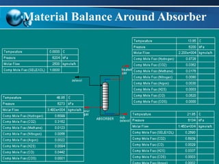
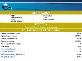
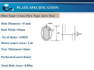
1
DESIGN OF ABSORBER
1. Introduction
2. Selection
3. Column Design
CONTENTS:
4. Specification Sheet
ABSORPTION
 The selective transfer of material from a
gas to a contacting liquid.
 The gas absorption process involves the
re-distribution of solute between the gas
phase and the liquid phase when the 2
phases come into close contact and
achieves equilibrium condition.
 Countercurrent operation
 Usually is carried out in vertical, cylindrical
columns or towers
Absorption and Stripping Equipments:
1.TRAY COLUMN
2.PACKED BED COLUMN
3.SPRAY TOWER
4.CENTRIFUGAL CONTACTOR
5.BUBBLE COLUMN
Absorption and Stripping Equipments:
Liquid in
Vapor in
Vapor
out
Liquid out
1
2
N–1
N
Trayed Tower
Liquid in
Vapor in
Vapor out
Liquid out
Spray Tower
Liquid in
Vapor in
Vapor out
Liquid out
Bubble Column
Liquid in
Vapor out
Vapor in
Liquid out
Centrifugal Contactor
Liquid in
Vapor in
Vapor out
Liquid out
Packed Column
TYPES OF ABSORPTION
1.Physical Absorption
2. Chemical Absorption
Physical
Absorption is
selected.
Why Physical Absorption?
 Physical Absorption Processes are generally most efficient
when the partial pressures of the acid gases are relatively
high, because partial pressure is the driving force for the
absorption.
 Solvents can be chosen for selective removal of sulfur
compounds
.
 Energy requirements for regeneration of the solvent are lower
than in systems that involve chemical reactions.
 Separation can be carried out at near-ambient temperature.
SELEXOL SOLVENT (DEPG):
 The SELEXOL solvent is a mixture of dimethyl ethers of
polyethylene glycol, and has the formulation
CH3(CH2CH2O)nCH3
where n is between 3 and 9
 The ability of SELEXOL® solvents to remain chemically non-
reactive with the gas is a desirable feature. This avoids the
formation of heat-stable salts that plague amine systems.
 It produces a highly enriched feed to the Claus unit and provides
maximum CO2 for any downstream process
FEATURES OF SELEXOL SOLVENT
 A very low vapor pressure that limits its losses to the treated
gas
 Low viscosity to avoid large pressure drop
 High chemical and thermal stability
the solvent is true physical solvent and does not react
chemically with the absorbed gases
 Non-toxic for environmental compatibility and worker safety
 Non-corrosive for mainly carbon steel construction: the
Selexol process allows for construction of mostly carbon steel
due to its non-aqueous nature and inert chemical
characteristics
FEATURES OF SELEXOL SOLVENT (cont):
 High solubility for HCN and NH3 allows removal without
solvent degradation
 High solubility for nickel and iron carbonyls allows for their
removal from the synthesis gas. This could be important to
protect blades in downstream turbine operation.
 Low heat requirements for regeneration because the solvent
can be regenerated by a simple pressure letdown
 Plate columns can be designed with more assurance than packed columns.
There is always some doubt that good liquid distribution can be maintained
throughout a packed column under all operating conditions, particularly in large
columns.
 The pressure drop per equilibrium stage (HETP) can be lower for packing
than plates; and packing should be considered for vacuum columns.
Pressure is very high i.e. about 6200KPa therefore plate column is
selected
Plates should always be considered for large diameter columns, say greater
than 0.6 m, where plates would be easy to install, and less expensive.
Plate columns are more suitable for handling non-foaming systems.
12
SELECTION OF PLATE COLUMN:
13
Material Balance Around Absorber
14
DESIGN CALCULATIONS:
1. Inlet gas specification:
Temperature = 322K
Pressure = 6273 Kpa
Molar Flow Rate = 34000Kgmol/hr
xco2 = 0.3161
Moles of CO2 in = 0.3161×34000= 10747.4Kgmol/hr
Moles of CO2 out = (100-92)/100× 10747.4
= 859Kgmol/hr
2.Specified CO2 separation = Ea =10747.4-859/10747.4 x100
=92%
Average tower conditions for K:
Temperature =298K
Pressure=6239Kpa
Kco2 at 6239Kpa and 298K =0.560
15
3. Minimum L/V for CO2
= 0.560 ×0.920=0.5152
16
=1.4
=0.720
= 0.720/.560 = 1.29
17
1.2 < Aio < 2.0
For Optimum Economic Design:
18
A=1.29 Eai=0.92
By successive iterations:
N=9
=9/0.4= 22.5
(E=20%-50%)
19
Used Trays=23
U = SURFACE TENSION OF THE
LIQUID IN THE TOWER, DYN/CM.
Vnf = Net Vapor Velocity At Flooding Velocity m/s
δ = Surface Tension of the liquid in the tower = 181.5 dyn/cm.
pL =Density Of Liquid= 1016 Kg/m3
At T=273K; P=6204Kpa
pG =Density Of Gas = 41.03 Kg/m3
At T=322 K ; P=6273Kpa
Csb= Souder and Brown Factor at Flood Conditions m/s
=Csb
Vnf
DIAMETER EVALUATION
21
Determination Of Csb:
Csb is obtained from after specifying a reasonable tray spacing
Standard Tray Spacings for large diameter columns are:
0.4m or 0.60m
22
Csb = 0.075
Vnf = 1.47m/s
Vn = Actual Velocity=0.7× Vnf
=1.03 m/s
Net column area=An =Volumetric Flow Rate/ Vn
=(14.2m3
/s ) / (1.03 m/s )
=13.8 m2
Column cross-sectional area= Ac =13.8/.85=16.2m2
DIAMETER EVALUATION
Diameter of column=(4Ac/π)0.5
DC= 4.5m
HEIGHT EVALUATION:
Hc= (Nact-1)Hs+ H
= (23-1)0.60 + 0.7
= 13.9m
TRAY HYDRAULICS
24
Let ts=0.60m ( range 0.15-1.0m)
1.Tray spacing, (ts):
25
Let dh= 5mm ( range2.5-12mm)
2. Hole Diameter, (dh ):
TRAY LAYOUT:
Let tT = 0.6×dh = 0.6×5= 3mm (0.4-0.7times dh )
Let Ip= 3×dh ( range 2.5-4.0 times dh)
26
3.Hole Pitch (Ip):
=3×5=15mm
4.Tray Thickness(tT ):
5.Weir Height (hw)= 50mm
For triangular pitch
Ratio Of Hole Area To Perforated Area (Ah/Ap )
=1/2π/4 ×dh
2
)/(√3/4 ×Ip
2
)
=0.90 × dh / Ip
2
=0.90 × (5/15)2
= 0.1
27
6. Ratio Of Hole Area To Perforated Area (Ah/Ap):
7. Downcomer Area:
Ad = .15Ac= .15x16.2=2.4m2
Ap = Ac-(2 X Ad)-Acz-Awz
=13.8-(2 x 2.4)-.138-.2025
= 8.6m
2
8. Perforated Plate Area (Ap)
28
(Ah/Ap )=0.1
Ah=8.6 x 0.1
Ah = 0.86m
2
10. NO OF HOLES
Ah = nh x (π /4) x dh
2
9. Total Hole Area (Ah)
29
IDENTIFICATION
ITEM
ITEM NUMBER
TYPE
NO. OF ITEMS
Purification
T-101
Plate Column
1
FUNCTION
Removal of Acid Gases (CO2,CO,H2S,COS,Ar)
COLUMN DESIGN SPECIFICATION
Operating temperature 298 K
Operating pressure 6239 KPa
Design temperature 328 K
Design pressure 6863KPa
No of equilibrium stages 9
Efficiency 50%
No of actual stages 23
Column diameter 4.5 m
Column cross-sectional area 16.2m2
Height of column 13.9m
31
PLATE SPECIFICATION:
Hole Diameter =5 mm
No of Holes =43822
Down comer Area= 2.4m2
Hole Pitch=15mm
Tray Thickness=3mm
Perforated area=8.6m2
Total Hole Area= 0.89m2
Plate Type= Cross Flow Type sieve Tray

Absorber with details including Material Balance

  • 1.
  • 2.
    1. Introduction 2. Selection 3.Column Design CONTENTS: 4. Specification Sheet
  • 3.
    ABSORPTION  The selectivetransfer of material from a gas to a contacting liquid.  The gas absorption process involves the re-distribution of solute between the gas phase and the liquid phase when the 2 phases come into close contact and achieves equilibrium condition.  Countercurrent operation  Usually is carried out in vertical, cylindrical columns or towers
  • 4.
    Absorption and StrippingEquipments: 1.TRAY COLUMN 2.PACKED BED COLUMN 3.SPRAY TOWER 4.CENTRIFUGAL CONTACTOR 5.BUBBLE COLUMN
  • 5.
    Absorption and StrippingEquipments: Liquid in Vapor in Vapor out Liquid out 1 2 N–1 N Trayed Tower Liquid in Vapor in Vapor out Liquid out Spray Tower Liquid in Vapor in Vapor out Liquid out Bubble Column Liquid in Vapor out Vapor in Liquid out Centrifugal Contactor Liquid in Vapor in Vapor out Liquid out Packed Column
  • 6.
    TYPES OF ABSORPTION 1.PhysicalAbsorption 2. Chemical Absorption
  • 7.
  • 8.
    Why Physical Absorption? Physical Absorption Processes are generally most efficient when the partial pressures of the acid gases are relatively high, because partial pressure is the driving force for the absorption.  Solvents can be chosen for selective removal of sulfur compounds .  Energy requirements for regeneration of the solvent are lower than in systems that involve chemical reactions.  Separation can be carried out at near-ambient temperature.
  • 9.
    SELEXOL SOLVENT (DEPG): The SELEXOL solvent is a mixture of dimethyl ethers of polyethylene glycol, and has the formulation CH3(CH2CH2O)nCH3 where n is between 3 and 9  The ability of SELEXOL® solvents to remain chemically non- reactive with the gas is a desirable feature. This avoids the formation of heat-stable salts that plague amine systems.  It produces a highly enriched feed to the Claus unit and provides maximum CO2 for any downstream process
  • 10.
    FEATURES OF SELEXOLSOLVENT  A very low vapor pressure that limits its losses to the treated gas  Low viscosity to avoid large pressure drop  High chemical and thermal stability the solvent is true physical solvent and does not react chemically with the absorbed gases  Non-toxic for environmental compatibility and worker safety  Non-corrosive for mainly carbon steel construction: the Selexol process allows for construction of mostly carbon steel due to its non-aqueous nature and inert chemical characteristics
  • 11.
    FEATURES OF SELEXOLSOLVENT (cont):  High solubility for HCN and NH3 allows removal without solvent degradation  High solubility for nickel and iron carbonyls allows for their removal from the synthesis gas. This could be important to protect blades in downstream turbine operation.  Low heat requirements for regeneration because the solvent can be regenerated by a simple pressure letdown
  • 12.
     Plate columnscan be designed with more assurance than packed columns. There is always some doubt that good liquid distribution can be maintained throughout a packed column under all operating conditions, particularly in large columns.  The pressure drop per equilibrium stage (HETP) can be lower for packing than plates; and packing should be considered for vacuum columns. Pressure is very high i.e. about 6200KPa therefore plate column is selected Plates should always be considered for large diameter columns, say greater than 0.6 m, where plates would be easy to install, and less expensive. Plate columns are more suitable for handling non-foaming systems. 12 SELECTION OF PLATE COLUMN:
  • 13.
  • 14.
    14 DESIGN CALCULATIONS: 1. Inletgas specification: Temperature = 322K Pressure = 6273 Kpa Molar Flow Rate = 34000Kgmol/hr xco2 = 0.3161 Moles of CO2 in = 0.3161×34000= 10747.4Kgmol/hr Moles of CO2 out = (100-92)/100× 10747.4 = 859Kgmol/hr 2.Specified CO2 separation = Ea =10747.4-859/10747.4 x100 =92%
  • 15.
    Average tower conditionsfor K: Temperature =298K Pressure=6239Kpa Kco2 at 6239Kpa and 298K =0.560 15 3. Minimum L/V for CO2 = 0.560 ×0.920=0.5152
  • 16.
  • 17.
    = 0.720/.560 =1.29 17 1.2 < Aio < 2.0 For Optimum Economic Design:
  • 18.
  • 19.
  • 20.
    U = SURFACETENSION OF THE LIQUID IN THE TOWER, DYN/CM. Vnf = Net Vapor Velocity At Flooding Velocity m/s δ = Surface Tension of the liquid in the tower = 181.5 dyn/cm. pL =Density Of Liquid= 1016 Kg/m3 At T=273K; P=6204Kpa pG =Density Of Gas = 41.03 Kg/m3 At T=322 K ; P=6273Kpa Csb= Souder and Brown Factor at Flood Conditions m/s =Csb Vnf DIAMETER EVALUATION
  • 21.
    21 Determination Of Csb: Csbis obtained from after specifying a reasonable tray spacing Standard Tray Spacings for large diameter columns are: 0.4m or 0.60m
  • 22.
    22 Csb = 0.075 Vnf= 1.47m/s Vn = Actual Velocity=0.7× Vnf =1.03 m/s Net column area=An =Volumetric Flow Rate/ Vn =(14.2m3 /s ) / (1.03 m/s ) =13.8 m2 Column cross-sectional area= Ac =13.8/.85=16.2m2
  • 23.
    DIAMETER EVALUATION Diameter ofcolumn=(4Ac/π)0.5 DC= 4.5m HEIGHT EVALUATION: Hc= (Nact-1)Hs+ H = (23-1)0.60 + 0.7 = 13.9m
  • 24.
  • 25.
    Let ts=0.60m (range 0.15-1.0m) 1.Tray spacing, (ts): 25 Let dh= 5mm ( range2.5-12mm) 2. Hole Diameter, (dh ): TRAY LAYOUT:
  • 26.
    Let tT =0.6×dh = 0.6×5= 3mm (0.4-0.7times dh ) Let Ip= 3×dh ( range 2.5-4.0 times dh) 26 3.Hole Pitch (Ip): =3×5=15mm 4.Tray Thickness(tT ): 5.Weir Height (hw)= 50mm
  • 27.
    For triangular pitch RatioOf Hole Area To Perforated Area (Ah/Ap ) =1/2π/4 ×dh 2 )/(√3/4 ×Ip 2 ) =0.90 × dh / Ip 2 =0.90 × (5/15)2 = 0.1 27 6. Ratio Of Hole Area To Perforated Area (Ah/Ap): 7. Downcomer Area: Ad = .15Ac= .15x16.2=2.4m2
  • 28.
    Ap = Ac-(2X Ad)-Acz-Awz =13.8-(2 x 2.4)-.138-.2025 = 8.6m 2 8. Perforated Plate Area (Ap) 28
  • 29.
    (Ah/Ap )=0.1 Ah=8.6 x0.1 Ah = 0.86m 2 10. NO OF HOLES Ah = nh x (π /4) x dh 2 9. Total Hole Area (Ah) 29
  • 30.
    IDENTIFICATION ITEM ITEM NUMBER TYPE NO. OFITEMS Purification T-101 Plate Column 1 FUNCTION Removal of Acid Gases (CO2,CO,H2S,COS,Ar) COLUMN DESIGN SPECIFICATION Operating temperature 298 K Operating pressure 6239 KPa Design temperature 328 K Design pressure 6863KPa No of equilibrium stages 9 Efficiency 50% No of actual stages 23 Column diameter 4.5 m Column cross-sectional area 16.2m2 Height of column 13.9m
  • 31.
    31 PLATE SPECIFICATION: Hole Diameter=5 mm No of Holes =43822 Down comer Area= 2.4m2 Hole Pitch=15mm Tray Thickness=3mm Perforated area=8.6m2 Total Hole Area= 0.89m2 Plate Type= Cross Flow Type sieve Tray