
Recommended
More Related Content
Similar to technical-packages.pdf |Goel scientific | Canada
Similar to technical-packages.pdf |Goel scientific | Canada (20)
Recently uploaded
Recently uploaded (20)
technical-packages.pdf |Goel scientific | Canada
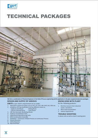
- 1. TECHNICAL PACKAGES 1. Absorption systems for gases such as HCl, Cl2, SO2, HBr. NH3, Br2, NOx etc. 2. Anhydrous HCl Gas Generation Unit by different routes viz. - Sulphuric Acid Route - Boiling Route - Calcium Chloride Route - Cyclic Route 3. HBr Gas Generator (By Boiling Route) 4. Sulphuric Acid Dilution Units. 5. Hypochlorite Manufacturing Units 6. MCA Condensation Assembly 7. Distillation - Conversion of Batch Process to Continuous Process. 8. Solvent Recovery 9. Iodine Recovery 10. Raw DCB Plant. DESIGN AND SUPPLY OF VARIOUS UNITS as per client's requirement are as under: KNOW-HOW WITH PLANT for the following products : 1. Bromine recovery from industrial waste / salt bittern. 2. Nitric Acid Concentration 3. Sodium Hypochlorite TROUBLE SHOOTING in above units as well as client's existing plant. We form a combination of Chemical Engineers in the field of Process engineering and its application in the glass equipments/process packages. 76 R The Transparent Specialist
- 2. TECHNICAL PACKAGES 77 WIPING FILM EVAPORATOR MOTOR CONDENSER RECEIVER RECEIVER PUMP WIPER Introduction Heat sensitive products like vitamins, hormones, enzymes or aromatic substances get adversely affected by way of material degradation due to higher temperature and residence time. This can be avoided if the reactions are carried under vacuum which allows the working temperature to be lowered, and by forming a thin film to reduce residence time, especially in case of liquids of high viscosity,orlowthermalconductivity. For these, GOEL introduces a specially designed range of Evaporators made of Borosilicate Glass. The range varies from laboratory size (80DN) to production plants(300DN). Construction The core of the unit is a rotating, fully corrosion resistant wiper system. This has four rows of PTFE wipers. These rows of wipers are divided into vertical segmentsandeachwiperismountedbetweentwoglassrods. A liquid distributor is located above the wipers. It distributes the medium, fed in through the feed pipe uniformly around the circumference of the evaporator beforethemediumisfinallypickedupbythewipersystemitself. The Evaporator has a vapour outlet which can be connected to a descending coil condenserandareceiver. The drive used for the wiper system is a standard geared-motor with an AC speed regulator. The wiper shaft is sealed by means of a mechanical seal. The evaporator body is constructed as a jacketed pipe. For heating, thermic fluid upto150Ccanbecirculatedinthejacket. The unit is designated by the jacketed pipe size. And the capacity of the unit depends on the evaporation rate which in turn depends on the HTA available, the type of heating media, and the evaporation environment i.e. vacuum conditions. 2 Model Size DN (mm) HTA (M ) WFE3 80 0.35 WFE4 100 0.47 WFE6 150 0.70 WFE9 225 1.06 WFE12 300 1.41 R The Transparent Specialist
- 3. Efficientgasabsorptiondependsonthefollowing: 1. Intimatecontact. 2. EfficientHeatTransfer. ThisisachievedinaFallingFilmAbsorberwhichisessentiallyashell&tubeheat exchanger in which both gas to be absorbed and absorbing liquid flow co- currently downward with extraction of heat by circulation of coolant in the shell.Theabsorbingliquidiscirculatedthroughatanktilldesiredconcentration is achieved. The liquid flows at such a rate that the tubes do not flow full of the liquid but instead, descends by gravity along the inner walls of the tubes as a thinfilm.Obviously,thisproducesamuchgreaterlinearvelocityforagivenrate flowthancouldbeobtainedifthetubeflowedfull. The equipment works as a number of water cooled wetted-wall columns in parallel and each tube is provided with distribution system on top to effect uniform distribution of both liquid and gas and also formation of a thin liquid filmontheinnersurfaceofthetube. 1. The heat of absorption is continuously removed. This ensures better absorption and product concentration as compared with conventional packedtower. 2. Low residence time and operating temperature ideally suited to heat sensitivematerials. 3. Borosilicateglassand PTFE contactpartsensurecorrosion/contamination freeoperation. 4. Bothstandardandcustombuiltunitsareavailable. 5. Capableofoperatingfromzerotomaximumgasflowrate. 6. Easeofinstallationduetolightweight. 7. Troublefreeandconsistentperformancewithminimalattention. 8. Wideapplicatione.g. HCl, HBr, NH , SO , H S,Br etc. 3 2 2 2 9. Lesscost. 10. Negligiblepressuredropcomparedtoconventionalcolumns. 11. Compactdesign Sleekandslender. 12. Both heat and mass transfer operations are incorporated in a single equipment. 13. Veryhighheattransfercoefficientastheliquidfallsinsteadofflowing. 14. Scaling of process fluid is minimal due to high velocity and ease of cleaningbysimpleacidcirculation. 15. Hot conditions are eliminated at all stages namely pipe, tanks and pumps etc. SALIENT FEATURES FALLING FILM ABSORBER LIMITATIONS 1. Not recommended for gases containing high proportion of inert (insoluble). 2. Not applicable if the gases are not highly soluble. SPECIFICATIONS Nominal Absorber No.of Tubes/ Max.Gas Absorption Max.Acid Prod. Sr. Size Area Tube OD Rate (Pure HCl) * Rate (As 30 % Height No. (mm) (m2) (mm) (kg/hr) HCl) (kg/hr) * (m) 1. 80 1.00 4/ 20 30 100 4400 2. 100 1.76 7/ 20 60 200 4500 3. 150 4.80 19/ 20 150 500 4600 4. 225 7.80 31/ 20 250 833 4920 5. 300 15.30 61/ 20 500 1667 5050 6. 400 36.00 143/ 20 1175 3917 5300 7. 450 47.00 187/ 20 1500 5000 5700 8. 600 84.00 333/ 20 2700 9000 5800 LIQUID GAS COOLANT VENT DRAIN COOLANT A VENT CW IN GAS LIQUID CW OUT TANK DETAIL - A DISTRIBUTOR TUBE SHEET PACKING TUBE TECHNICAL PACKAGES 78 R The Transparent Specialist
- 4. Commercial sulfuric acid is a cheap commodity and in its dilute and impure form does not have good market potential. Disposal by neutralization with lime is associated with, problems of solid (calciumsulfate)handlingandalsoaddstothecost. To overcome these problems GOEL offers know-how, design engineering services of sulfuric acid concentration system in which the dilute sulfuric acid generated is reconcentrated to desired level for reuse. That is to say a twofold benefit of eliminating the disposal problem and minimizing fresh commercial acidrequirement. PROCESS DESCRIPTION The process is extremely simple & involves concentration of dilute sulfuric add by evaporation using steam/thermic fluid as heating media under vacuum. The dilute feed is preheated & fed to a series of evaporators in stages to achieve the concentration level. The vapors from the evaporators are condensed and drainedoutthrough barometriclegsandnon-condensablesareremoved byan ejector.Thefinalproductiscooledanddrawninthestoragetank. REQUIREMENT OF UTILITIES The requirement of utilities viz. steam/thermic fluid, cooling water and power vary widely depending on feed rate, feed concentration and product concentration. For example for a plant having 50TPD feed containing 50% H2S04 the consumption of utilities for achieving 70% concentration are given below. 1.Steam@6bar{g)pressure 800Kg/hr 2.Coolingwater@30°C 70CuM/hr 3.Power 15 KW SULPHURIC ACID CONCENTRATION SYSTEM PRODUCT FEED TWO STAGE SULFURIC ACID CONCENTRATION SYSTEM CWR CWS COOLING WATER WATER / STEEM 1 2 3 4 C C 5 6 7 8 STEAM KEY 1 - PRODUCT COOLER 2 - FEED PREHEATER 3 - 1ST, STAGE EVAPORATOR 4 - 2ND, STAGE EVAPORATOR 5 - MIST ELIMINATOR 6 - DIRECT COOLER 7 - EJECTION 8 - SEAL POT C - STEAM CONDENSATE CWS - COOLING WATER SUPPLY CWR - COOLING WATER RETURN TECHNICAL PACKAGES 79 R The Transparent Specialist
- 5. Bromine is available in the sea bittern, as well as Industrial waste e.g. Aq. HBr / Aq. NaBr / Aq. KBr. The Bromine concentration in the feedstock varies from 2 gpl to300gplfromindustrytoindustry. GoelOffersuitablebrominerecoveryplantforthevariousfeedstockbasedonhis 20 years expertise in this field. Goel suggest cold process for bromine concentrationbelow3gplandHotprocessabove3gpl. Thepackageconsideredisschematicallyshownindrawingenclosedherewith. The process consists of simultaneous chlorination & steam blowing. The feed stock acidic in nature is preheated to near its boiling in feed pre heater and then fedtothemaincolumnwheresteamandchlorineareblownsimultaneously.The bromine as set free by chlorine are steam distilled. The liberated bromine together with steam and some excess chlorine is condensed in the condenser. The condensate is taken to a gravity separator where bromine and bromine water are separated. While bromine is taken in the purification column the aq. layer is recycled into the main column. Crude bromine is purified under reflux and pure bromine is collected in the receiver. All uncondensed vapour pass throughthetailscrubbertorecoverthelasttracesofbromine. BROMINE RECOVERY SYSTEM PRODUCT CWS CHW 10 9 CHW 13 12 CHW 11 7 8 6 5 4 4 CWS CHW 3 STEAM STEAM R CL2 2 EFFLUENT FEED R 1 TO VENT CWS - COOLING WATER SUPPLY CWR - COOLING WATER RETURN CHW - CHILLED WATER R - ROTAMETERS BATTERY LIMITS GOEL CLIENT SR. DESCRIPTION 1. TAIL SCRUBBER 2. FEED PREHEATER 3. Br STRIPPING COLUMN 2 4. Br CONDENSERS 2 5. PHASE SEPERATOR 6. CRUDE Br RECEIVING VESSEL 2 7. REBOILER 8. PURIFICATION COLUMN 9. PRODUCT COOLER 10. PRODUCT COOLER 11. VENT CONDENSER 12. PRODUCT RECEIVER VESSEL 13. PRODUCT COOLER TECHNICAL PACKAGES 80 R The Transparent Specialist
- 6. Commercial Hydrochloric Acid is available in the market as 30% aqueous solution. But for certain applications e.g. bulk drug and pharmaceuticals, HCl is required in anhydrous state for critical reactions where moisture cannot be tolerated. Such users generate anhydrous H C l from commercial grade for their captive consumption. METHOD Several methods have been adopted by industries. But generation by Sulphuric Acid Route and Boiling Route are commonlypracticed. WeofferCalciumChlorideRoutealso. Indicative Raw-material & Utilities for 20 kg/hr HCl Working Principle Process Outline Salient Features Hydrochloric acid is highly soluble in water but the solubility diminishes in presence of H2SO4 and at 70 to 75% H2SO4 concentration its solubility is negligible. Thus by adding (98%) commercialSulphuricacidtocommercialhydrochloricacid(30%)in proper ratio the entire HCl can be liberated in gaseous form leaving 75%H2SO4asspentacid. Meteredquantitiesofcommercialsulphuricacidhydrochloricacids are fed to the unit where they mix in the Mixing Zone. The gas generated forms a froth and enters the Generation Zone where while traveling through a bed gas is released which travels upwards through the Drying Zone. Here the gas comes in intimate contact with downward flow of 98% H2SO4. The dry gas leaving the unit passes through a rotameter. The spent liquor containing 70-75% H2SO4passesthroughtheCoolingZonebeforebeingdischarged. - Operational reliability the unit can be started/ stopped in seconds. - Available in wide range of capacities from 5 to 200 kg/hr of dry HCl. - Except cooling water no other utility e.g. steam chilled water etc. required. - Anhydrous gas. - Capable of operating from 25 to 120%. - Ease of installation. - Negligible pressure drop. - High efficiency 99%. Aqueous hydrochloric acid forms a maximum boiling point o azeotrope at 110 C containing 20.24% HCl at atmospheric pressure. Thus by distilling commercial hydrochloric acid (30%) pure HCl gas can be generated and spent acid will containover20.24% HCl. - Operational reliability. - Available in wide range capacities from 5 kg/hr to 200 kg/hr of dry HCl. - Except commercial hydrochloric acid, no other raw-material is required. - Anhydrous gas. - Capable of operating from 25-100%. - Ease of installation. - Negligible pressure drop. 30% HCl - 70 kg/hr 98% H2SO4 - 170 kg/hr 3 Cooling Water - 2 m /hr 30% HCl - 200 Kg/hr Saturated Steam - 50 kg/hr 3 Cooling Water - 3.5 m /hr 3 Chilled Brine - 4 m /hr Metered quantity of commercial hydrochloric acid is preheatedinapreheaterbysteamandfedtoafractionating column with steam as heating media in the reboiler. The vapours leaving the column are condensed with coolant as cooling water and chilled brine in stages.The relatively dry gas passes through a mist eliminator and then through a rotameter. The spent acid containing 22% HCl is cooled throughacoolerandthendischarged. HCL GAS 98% H2SO4 DRYING ZONE 30%HCL MIXING ZONE GENERATION ZONE SPENT ACID CW SULPHURIC ACID ROUTE HCL GAS DEMISTER CONDENSER CONDENSER CHW CW COLUMN PREHEATER S 30% HCL S COOLER CW REBOILER 20-22% HCL BOILING ROUTE TECHNICAL PACKAGES ANHYDROUS HCL GAS GENERATOR 81 Route Sulphuric Acid Route Boiling Route R The Transparent Specialist
- 7. WorkingPrinciple: Hydrochloricacidandwaterformamaximumboilingpointazeotropeat11O°C corresponding to a concentration of 20.24%; (w/w) HCl. By adding concentrated CaCl solution to commercial hydrochloric acid the azeotrope 2 point is eliminated and the entire' HCl becomes available for liberation by distillation. Anhydrous HCl gas generation through Calcium Chloride Route is themostenvironmentalfriendlytechnique. ProcessDescription: The above principle- is achieved in practice by feeding metered quantities of commercial HCl and 50% CaCl -solution to a stripping column with a steam 2 heated re-boiler at bottom. The effluent from bottom of the column is a dilute acidic calcium chloride solution which is concentrated to 50% in a evaporator and re-used. The vapor leaving is condensed stage wise with cooling water and chilled brine as coolant. The relatively dry gas passes through a mist eliminator andthenthrougharotametertothepointofconsumption. Rawmaterialutilityrequirements: Theindicativerequirementsfor20Kg/hr HClgasgeneratoraregivenbelow. 1. 30-32% HCl,(Kg/hr) : 66 3 2. Coolingwaterat30°C(M /hr) : 4 3 3. Chilledbrineat-10°C(M /hr) : 3 2 4. Steamat6Kg/cm (g) : 150 ANHYDROUS HCl GAS GENERATOR - CALCIUM CHLORIDE ROUTE LEGEND R - REBOILER D - COLUMN E - EVAPORATOR C1 - PRIMARY CONDENSER TECHNICAL PACKAGES LEGEND C2 - SECONDARY CONDENSER R1 -FEED HCL ROTAMETER R2 -FEED CACL ROTAMETER 2 R3 -DRY HCL GAS ROTAMETER LEGEND CW - COOLING WATER CHB - CHILLED BRINE C3 - CONDENSER P - PUMP The limitations of batch distillations are naturally circumvented in continuous distillation as shown in fig.2 which is a typical fractionating unit comprising of ratification &stripping sections. Here feed is continuously fed to the column withwithdrawaloftop&bottomproducts.Theprocesstakescareonitsownby simplymaintainingtheflowratesoffeed&Utilities. However when more than two products are desired as in case of multicomponent systems additional columns are required as each column is capable of giving two products only. That is to say, for multicomponent system only one product is obtain in relatively pure form from each column. The other product containing the remaining components is fed to a subsequent column where again one product is obtained in relatively pure form. The addition of columns continue till the system becomes binary & both components are separatedinthefinalcolumn. An important principle to be emphasized is that a total n-1 fractionators are required for complete separation of system of n components. Which of the two products in a column is to be obtained in relatively pure form depends on relative volatility of each component in the feed stock. For example consider a ternary solution consisting of a components A, B & C whose relative volatilities are in that order (A most volatile). In order to obtain three substances in substantially pure form either of the schemes shown in fig-3 may be used. Whichofthetwoschemeswouldbeuseddependsontherelativedifficultiesof separation in each method and the choice calls for finer considerations of principles of distillation. However scheme (b) is usually preferred since it requiresonevaporizationofsubstanceA. CONTINUOUS DISTILLATION SYSTEM DISTILLATE CONDENSER FEED COLUMN STEAM CONDENSATE BOTTOM REBOILER 82 R The Transparent Specialist DRY HCL GAS C2 C1 CW CHB R3 20L 20L 20L R2 30%HCL R1 D C3 TO SCRUBBER TO EFFLUENT E R FEED 30%HCL P 50% CACL CIRCULATION LINE 2 FEED TANK P BATTERY LIMIT GOEL CLIENT
- 8. Solvents are universally used in wide varietyof industries, their use byno means being limited to the chemical industry. The choice of solvents such as xylene, acetone, butyl acetate, methanol etc. depends on the type of application and economicalconsiderations. In many cases, the solvent - after use - is contaminated and not in a reusable condition. Purchase of fresh solvent and disposal costs of the contaminated solvent can prove expensive operations. Therefore, it makes sound economic sensetoinvestigatetherecoveryofcontaminatedsolventsforre-use. GOEL designandsupplysolventrecoveryplantswhicharecapableofrecovering solventsfromafewkg/daytomanytons/day. Applications: 1. GOEL SolventRecoveryUnitsarecarefully designedtocaterthe specific requirement for eachdutyforwiderangeofsolvents. 2. ContinuousDistillationUnitshavedistinct advantages,suchas 2.1. EaseofOperationduetosteadystateworking. 2.2 Economicaldesignaseachequipmentviz. column,condenserreboileris designedfor uniformandsteady-load. 2.3 Uniformproductquality, 2.4 Uniform&lowconsumptionofutilities. 2.5 Higherproductivityasdowntimeforstart-up, emptyingetc.is eliminated. The outline flow-sheet of the plan is shown in Figure. Regulated quantity of feed is fed to a distillation column from an overhead vessel. The overhead vessel is provided with a vent condenser with chilled water circulation to arrest loss of acetone vapor. The reboiler at the bottom of column in this case was a steam heated oil-bath. The vapors from top of the column pass through primary and secondary condensers with cooling water and chilled water circulation. The condensate is partially refluxed and balance continuously drawn out and collected in receiver provided with a vent condenser. The residue from the re- boileriscontinuouslydrainedout. SOLVENT RECOVERY CHW FEED CW CHW FEED VESSEL COLUMN CHW PRODUCT VESSEL REBOILER PRODUCT CW REFRUTE DRAIN TECHNICAL PACKAGES CONDENSER FEED COLUMN CONDENSER COLUMN A+B+C C(+B) B(+C) A(+B) A+B (C) CONDENSER FEED COLUMN CONDENSER COLUMN A+B+C B+C(+A) C(+B) B(+A) A(+B) Component given in bracket are in small quantities. 83 R The Transparent Specialist
- 9. PRECIOUS METAL REFINING Borosilicate glass is inert to almost all materials. Due to which it is now widely used in Precious Metal Refining Industry. Borosilicate Glass is the only material which doesn't absorb precious metals. Its transparency allows ease of visualization&smoothsurfaceallowseaseofcleaning. We have supplied various capacity glass assemblies in precious metal refinery for Aqua Regia solution. Our Glass Container/Vessel are also used as dissolution, precipitator and separator for Gold /silver/ platinum recovery with AquaRegia/Hydrazinesolution. Scrubbing Unit :The fumes generated by Aqua Regia in a gold refining process aretoxic.Wedesign&offersuitablecapacityGlassScrubberUnitforremovalof NOX Fumes. Filer Unit :We also offer Glass Filter Unit on wheels for removing of precious metalfromtheAquaRegiasolution. Nitric Acid Boiling Apparatus :Nitric Acid Boiling Apparatus with condenser for Laboratorytestingisalsoavailablewithus. Sampling Tubes :Vacuum Tubes (VPT 111 ) for removal of samples from the batcharealsomanufacturedbyus. TECHNICAL PACKAGES 84 ROTATING DISC EXTRACTION COLUMN Introduction Separationwillbecarriedoutnormallywiththehelpofdistillationbutwhenitis not feasible by distillation or ineffective liquid-liquid extraction is one of the process to consider. There few mixtures are having close boiling points components or heat sensitive components which can not withstand the temperature of distillation, even under vacuum may often be separated from impurities by extraction which utilize the chemical properties like specific gravity,solubilityetc.insteadofvapourpressuredifferences. Separations by liquid-liquid extraction can be defined as the selective removal of one or more components either from a homogenous liquid mixture or from a solution,usingasecondliquidorsolvent,whichispartiallyorwhollyimmiscible withthefirst. Construction Thecoreoftheunitisarotatingdiscwithvariednoofstagesbetween1mto2m height. The RDC blade can be made of PTFE or SS 304 or SS 316 depending on thecustomerrequirement. The system can be supplied with or without dosing pump and two feed vessels as well as two receivers.The drive used for the rotation of the disc is a standard geared-motor with an AC speed regulator. The agitator shaftis sealed bymeans ofamechanicalseal. The outer column can be constructed as a jacketed pipe or without jacketas per the customer requirement. The unit is designated by the diameter of the extraction column and no. of stages as per the customer specification depends ontheflowratesandpropertiesofthechemicalused. Model Size DN (mm)Hight RDC3 80 2.0 RDC4 100 2.0 RDC6 150 2.0 RDC9 225 2.0 RDC12 300 2.0 RDC16 400 2.0 NEW NEW HCL HNO3 ADDITION VESSEL CONDENSER REACTOR FILTER VFD VFD VFD FLAME PROOF MOTOR IMPALLER ROTATING DISC (ROTOR) STATIC PLATE SS / PTFE LINED STIRRING SHAFT R The Transparent Specialist
- 10. 85 R The Transparent Specialist TECHNICAL PACKAGES NITRIC ACID PURIFICATION SYSTEM VENT TO SCRUBBER REFLUX CONDENSER CWR CWS FEED ACID COLUMN VENT TO SCRUBBER FEED VESSEL CWS CWR CWR CHWS VENT CONDENSER CWS CWR WASTE ACID AIR BLEACHING COLUMN EVAPORATION VESSEL CWR CWS CWS CWR PRODUCT ACID COOLER The process to purify industrial/technical grade nitric acid involves a single stage distillation to leave non- volatile impurities in the still bottoms. 69% – 70% concentrated nitric fluid is delivered by means of a metering pump from a storage tank into the glass still which is equipped with Electrically heated Oil Bath. The acid vapors flow through a mist removing packed section to the Glass condenser. Depending on the desired concentration high pure water can be added as a diluent to the condensed product before entering the bleach column. Clean air is introduced at the base of the bleacher. Air and oxides of nitrogen are vented through a condenser to a scrubber. Entrained nitric acid is not returned to the bleaching column but collected separately. Removing of allNOxoutofelectronicgradenitricacid. NEW Capacity 40 kg/hr Commercial grade Nitric Acid - 69-70% 44 kg/hr Electric Heater 48 kw Cooling Water @ 7 deg. C* 4-5 Cu.M/hr Space Requirement 3 x 3 x 8 m Design Basis & Requirement of Utilities : Size Available 5 kg/hr to 500 kg/hr
- 11. 86 R The Transparent Specialist TECHNICAL PACKAGES HCL PURIFICATION SYSTEM ME MIST ELIMINATOR R1 ROTAMETER FOR FEED R2 ROTAMETER FOR CIRCULATION OF HCL R3 ROTAMETER FOR PRODUCT CWS COOLING WATER SUPPLY CWR COOLING WATER RETURN CHWS CHILLED WATER SUPPLY CHWR CHILLED WATER RETURN P PUMP FEED TANK VENT TO SCRUBBER CHWR CHWS CWR CWS CWR CWS CHWS CHWR CHWS CHWR ME CHWS CHWR R2 R3 PRODUCT CHWR CHWS CHWR CHWS EVAPORATION VESSEL IMPURITY HCL PURIFICATION P R1 Commercial Grade Acid (30% HCL) is feed to the Reboiler through Flow meter.ThefeedwillbeheatedinRe-Boilerbyheatingmediatoevaporate the 20-22% HCL. The 20-22% HCL+ Water Vapour generated will be condensed in Top Cooler with Cooling water & chilled water. The gas leaving the top will be of pure HCL gas will fed to the scrubber wherein it will be scrub further with condensed Azeotropic solution or with fresh processwatertomakeultrapureHCl. Therearevariousoptionsto makeultrapureHCL Dependingon following factor:1.feedquality2.Effluentgeneration3.Capitalinvestmentetc… Goel offers various solution for HCL purification based on customerneed. Sr. Feed Product Cooling Chilled Power No. 30% HCl 36-37% Water Water (w/w) HCl @32 deg. C @8 deg. C Kg/hr Kg/hr Cu. m. / hr * Cu. m. / hr * KWH (Max.) 1 15 12.5 8-10 5-6 10 NEW