Downloaded 32 times


![ACETONE ABSORPTION COLUMN
Required: “CONFIDENTIAL” Sh.a. DESIGNED: Arberor MITA Design group“ELMAGERARD”
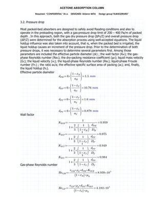
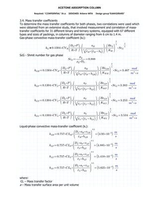
where:
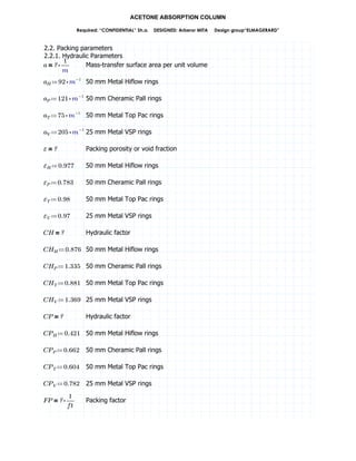
– Mass transfer factor
a – Mass transfer surface area per unit volume
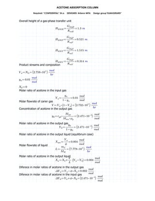
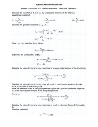
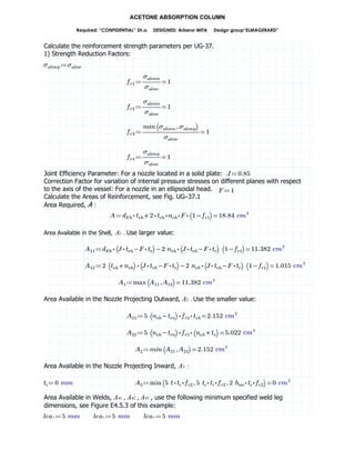
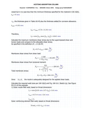
3.5. Packing Height
In those systems handling dilute solutions and when Henry’s law applies, is very usual and
convenient to work with overall mass-transfer coefficients in order to calculate the packing
height (Z), which can be determined by the following expression:
8„ —§ˆ¢c £ˆ¢c
where:
HtOG – Overall height of a gas-phase transfer units
NtOG – Overall number of gas-phase transfer units
Prior to determine the values of HTU and NTU, it will be necessary to calculate several
parameters first, which are the inlet gas molar velocity [GMy(1)]; the outlet gas molar velocity
[GMy(2)]; the average molar gas velocity (GMy); the inlet liquid molar velocity [GMx(2)]; the outlet
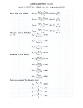
liquid molar velocity [GMx(1)]; the absorption factor at the bottom [A(1)] and top [A(2)] of the
column ; the geometric average of the absorption factor (A) ; the ethanol molar composition
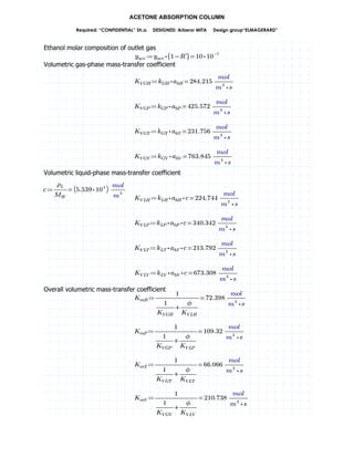
of outlet gas [yeth(2)] ; the volumetric gas-phase (KvG) and liquid-phase (KvL) mass-transfer
coefficients ; the overall volumetric mass-transfer coefficient (Km); the overall height of a gas-
phase transfer unit (HtOG) ; the overall number of gas-phase transfer units (NtOG); and finally
the packing height (Z).
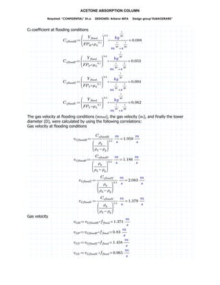
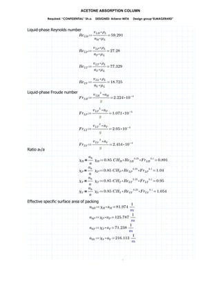
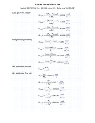
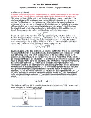
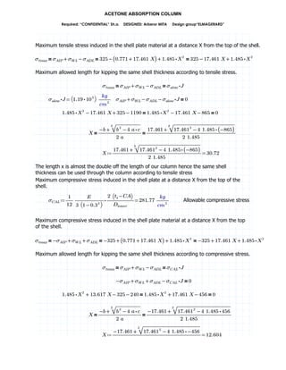
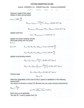
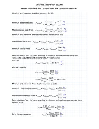
Inlet gas molar velocity
8¤¥h¦ AAA
` §c
9… ¨u
Gas molar flow rate
C§c –AAA
9bc †g
$c
˜™ 9FVQRE BTjde AA2©
)'
Inlet gas molar velocity
C¤¥h¦D –AAA
` §c
9… ¨D
u E`VYTW AA2©
92u %
C¤¥h¦I –AAA
` §c
9… ¨I
u RQVFRB AA2©
92u %
C¤¥h¦P –AAA
` §c
9… ¨P
u BTTVRWE AA2©
92u %
C¤¥h¦S –AAA
` §c
9… ¨S
u YYVRQW AA2©
92u %
8¤¥h© AAAAA
` ˜™ f§c §gˆ‹elmde
9… ¨u
Molar flow of ethanol absorbed
C§efgelm –99AAA
9bc †g
$c
7efg vw TVQYY AA2©
%
Outlet gas molar velocity](https://image.slidesharecdn.com/acetoneabsorptioncolumn-190919145054/85/Acetone-absorption-column-22-320.jpg)
![ACETONE ABSORPTION COLUMN
Required: “CONFIDENTIAL” Sh.a. DESIGNED: Arberor MITA Design group“ELMAGERARD”
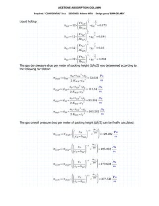
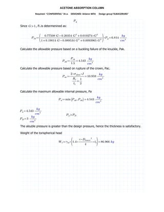
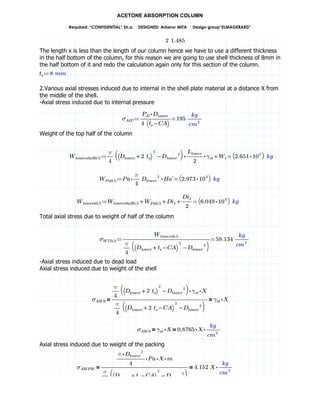
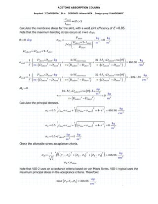
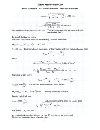
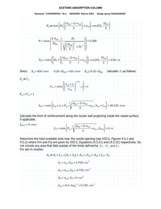
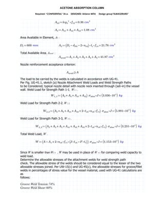
Number of gas-phase transfer units
C´ˆ²cD –9AAAA
fp³ pi
fƒp³ ƒpi
qr
˜
h
™
AA
ƒp³
ƒpi
d
i
e
FXVFTB
C´ˆ²cI –9AAAA
fp³ pi
fƒp³ ƒpi
qr
˜
h
™
AA
ƒp³
ƒpi
d
i
e
FXVFTB
C´ˆ²cP –9AAAA
fp³ pi
fƒp³ ƒpi
qr
˜
h
™
AA
ƒp³
ƒpi
d
i
e
FXVFTB
C´ˆ²cS –9AAAA
fp³ pi
fƒp³ ƒpi
qr
˜
h
™
AA
ƒp³
ƒpi
d
i
e
FXVFTB
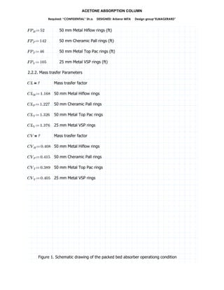
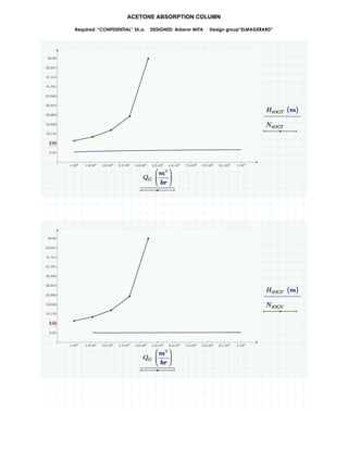
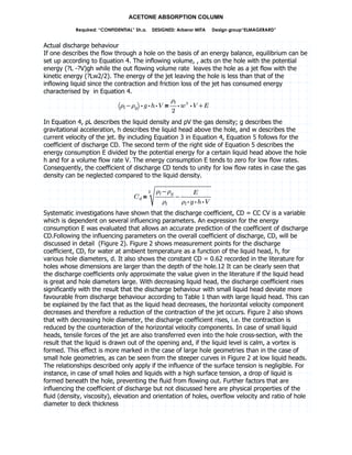
Packing height
C„ –9´ˆ²cD §ˆ²cD XTVBYQ 2
C„ –9´ˆ²cI §ˆ²cI BFVTE 2
C„ –9´ˆ²cP §ˆ²cP XRVB`W 2
C„ –9´ˆ²cS §ˆ²cS QVFEX 2
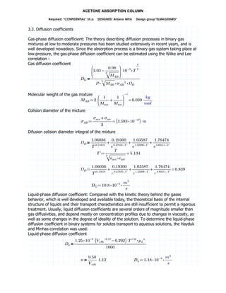
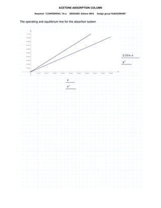
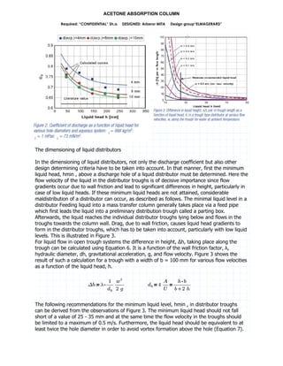
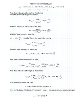
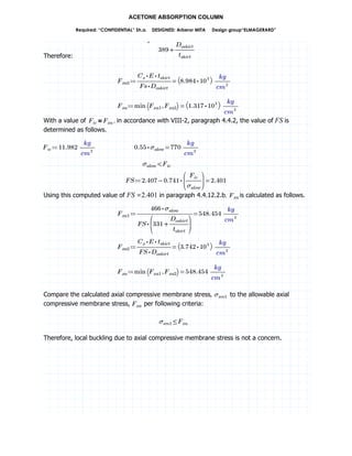
3.6. Operating and equilibrium lines
The operating line will be elaborated using the following data:
Mole fraction of acetone in inlet gas mixture [yace(1)] = 0.01
Mole fraction of acetone in outlet gas mixture [yace(2)] = 9FV`QB BTGj
Mole fraction of acetone in inlet liquid [xace(2)] = 0.
Mole fraction of acetone in outlet liquid [xace(1)] = TVTTX
The operating line points
C7ww TVTB
9FV`QB BTGj
µ
¶·
¸
¹º
C»ww TVTTX
T
µ
¶·
¸
¹º
The equilibrium line for the absortion system
8887w 9• » 9A§
» 9FVXB` »
C7wss»tt 9FVXB` »
The operating and equilibrium line for the absortion system](https://image.slidesharecdn.com/acetoneabsorptioncolumn-190919145054/85/Acetone-absorption-column-27-320.jpg)


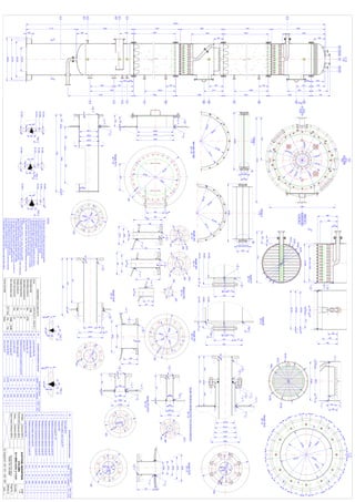
This document details the design of an acetone absorption column. It considers four different packing types (Pall®, Hiflow®, Top Pak® and VSP®) to determine the optimal configuration based on column dimensions, mass transfer coefficient, and pressure drop. The influence of gas and solvent flowrates on key parameters is evaluated for each packing type. The goal is to remove acetone from an air stream using a countercurrent absorption process with water as the solvent. Design parameters like column diameter, packing height, mass transfer coefficients, and pressure drops are calculated.


