This document provides information on a chemical engineering plant design course including:
- The course code, credit hours, instructor contact details, and course contents which include topics like process design, hazard analysis, equipment design, and cost analysis.
- The course learning outcomes related to applying design considerations, optimization techniques, developing safety protocols, and implementing a feasible process design.
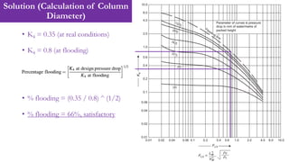
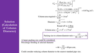
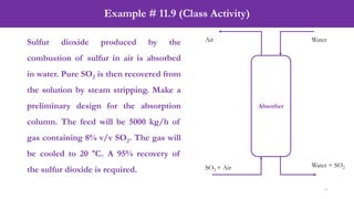
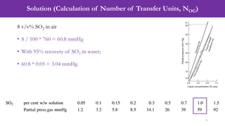
- An example problem on the preliminary design of an absorption column for recovering sulfur dioxide from air, including calculations to determine the number of transfer units and column diameter.


![Solution (Calculation of Number of Transfer Units, NOG)
11
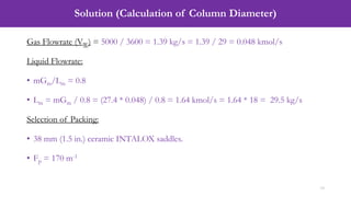
1 % w/w SO2 = 59 mmHg
• Mole Fraction (Vapor) = Pi / P = 59 / 760 = 0.0776
• Mole Fraction (Liquid) = [(wt. of SO2 / Mol. wt.)] / [(wt. of SO2 / Mol. wt.) + (wt.
of H2O / Mol. wt.)]
• Mole Fraction (Liquid) = [(1/64)] / [(1/64) + (99/18)] = 0.0028
• Slope = Mole Fraction (Vapor) / Mole Fraction (Liquid) = 0.0776 / 0.0028 = 27.4](https://image.slidesharecdn.com/week04lecture07packedcolumn-240309090839-acf91b31/85/Week-04_Lecture-07_Packed-Column-pdf-11-320.jpg)
![Solution (Calculation of Number of Transfer Units, NOG)
13
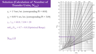
If the equilibrium curve and operating lines can be taken as straight, and the solvent
feed is essentially solute free, the number of transfer units is given by:
NOG = 1/(1-0.8) * ln[(1 – 0.8)*20 + 0.8] = 7.84 ≈ 8](https://image.slidesharecdn.com/week04lecture07packedcolumn-240309090839-acf91b31/85/Week-04_Lecture-07_Packed-Column-pdf-13-320.jpg)